1
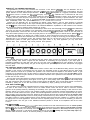
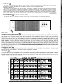
AIASHVillETM
400
f
WARNING: TO PREVENT ELECTRICAL SHOCK OR FIRE HAZARD, DO NOT EXPOSE
THIS APPLIANCE TO RAIN OR MOISTURE. BEFORE USING THIS APPLIANCE,
READ THE OPERATING GUIDE FOR FURTHER WARNINGS.
NASHVILLE’” 400 GENERAL DESCRIPTION
Congratulations, you have just purchased the successor of the famous LTD@ 400. The new Nashville’” 400 is a
refinement of the capabilities and features of the older LTD@ 400 and has far surpassed that unit in performance. This new
system features our more efficient Super Structure’“, 15” Black Widow@ loudspeaker in a ruggedly constructed enclosure
of 3/4” wood, which is covered with 34-ounce heavyduty vinyl Tolex. The Nashville 400 is state-of-the-art with every
aspect of design and construction, and we have included our famous DDT@ compression circuitry, which senses the onset
of clipping from the power amp and compresses the signal only to the extent necessary to prevent distortion. The active
tonecircuitryisverysimilartothat used in ourSession@/LTD@,exceptthatthecontrols havesomewhatgreaterrangeand
allow considerably better noise performance.
Overall, the new Nashville may be considered the ultimate “Clean Machine” and has been designed to minimize
distortion from the input through to the output including the loudspeaker. This system is single channel and features a
new pre EQ patch, which allows effects devices to be interfaced before the equalization so that maximum tone coloration
may be used to enhance whatever effects devices are chosen.
The power section of this unit features 210 watts RMS (the same as our older Session@ 400 and LTD@) and it delivers this
power into a 4 ohm load. The addition of our compression circuit enables the Nashville 400 400 to be louder and cleaner
than its predecessors, which were also 210 watts, but did not have the DDT@ compression circuit. On the rear panel we
have also included preamp out and power amp input jacks for the all important patch of effects devices post the EQ and
also provides the ability to go directly into a studio console or sound reinforcement mixer with the preamp output.
Please read this manual and understand the control functions and try to adapt the technology that is designed within the
Nashville 400 to your particular needs. We certainly believe that you will find this unit to be the most advanced
state-of-the-art system for steel guitar, keyboards, lead guitar, fiddle, or any other application you may have which
requires clean, clear, undistorted, high sound pressure level operation.
INPUTS (1)
The Nashville 400 has two inputs, one featuring high gain and the other one third as much gain. The High Gain Jack is
the input normally used, unless a signal from the instrument is overloading the input preamp. If your input signal is
overloading (distorting) the High Gain Jack, then the Low Gain Jack (-10 dB) should be used. Because of the unique
switching design of the input circuitry, the gain of both high and low jacks are preserved when instruments are plugged
into both jacks.
PRE GAIN/PULL BRIGHT CONTROL (2)
The Pre Gain Control is similar to a conventional volume control in that it is the first level setting device in the system.
Operation of this control is conventional and even though the associated circuitry is quite different from the older totally
passive units there should be no problem with operation. This control should be adjusted to the desired amount of gain
necessary for the instrument, but it is also working in conjunction with the Post Gain Control. Once the Post Gain Control
is adjusted properly then the gain desired for each individual instrument that is patched into the Nashville 400 should be
set with the Pre Gain Control.
The Pre Gain Control also features an integral “pull switch” which adds a significant boost (6 dB) to the high frequencies
when activated. This high frequency boost gives a nice “edge” to clean playing styles. Steel guitarists will usually adjust
their high frequencies with the Presence Control but lead players will definitely enjoy the pull bright feature. The boost is
activated by “pulling out” on the Pre Gain Control and defeated by simply “pushing” the knob inward.
POST GAIN CONTROL (3)
The Post Gain Control sets the overall level from the preamp which feeds the 210 watt power section of the Nashville400.
The action of this control is very similar to that of a master volume control and can be used to control the overload
dynamics of the preamp section by decreasing the sensitivity of the power amp. Normal settings of this control for clean
operation will be from 12:00 o’clock to full clockwise. Rotating thecontrol clockwise increases thesensitivityof the power
amp and the overall volume level of the system. Some studio applications, because of low noise requirements may need a
fairly low setting of the Post Gain Control, but, please be careful to keep the Post Gain Control adjusted to at least the same
number setting as the Pre Gain Control to avoid preamp overload which may cause distortion. An average setting for the
Post Gain Control for normal conditions during concert situations would be around the number5 to 7 positions and could
be slightly lower for studio applications. Once this control is adjusted properly for the amount of sensitivity you desire for
the overall system, then the gain of the individual instrument patched in should be accomplished with the Pre Gain
Control.
PRE EQ PATCH (4)
The unique pre equalization patching*jacks have been provided for use with external devices such as volume pedals,
effects units, etc., etc. This feaure allows external devices to be patched into the system after the input preamp but before
(pre) the EQ (tone controls). The sensitivity of the Pre EQ Patch has been optimized for low level (instrument signal) type
devices. NOTE! Line level (1 volt) devices should be patched at rear panel - preamp out and power amp input loop.
Shielded cables should be used for all external patching of effects devices.
EQUALIZATION
LOW EQ CONTROL (8)
The Low EQ Control is of the active”shelving type”and provides lowfreqency boost in the clockwise positions and low
frequency cut in the counterclockwise positions. Flat response is obtained in the vertical 12:00 o’clock position, as
indicated by the zero in the center of the rotation. The action of this control is more or less conventional and no operational
problems should be encountered. You should, however, avoid excessive low end boost since this greatly affects your
amps power reserve (headroom). The Low EQ Control is capable of more than 15 dB of boost or cut and you should be
aware that each 3 dB of boost doubles the amount of power necessary to produce the desired amount of low end. Even the
200 watt RMS capability of the Nashville 400 may be overloaded by excessive low end boost at high volume levels.
MID EQ CONTROL (8)
This control enables a boost or cut of 15 dB in the vital mid-range frequencies. Added versatility is possible because of
the ability to vary the operating center point throughout the mid-range from 150 Hz to 1500 Hz by use of the freqency shift
control. The Mid EQ Control works in a similar manner to the Low and High EQ Control and should present no operational
difficulties. Clockwise settings increase “fat” mid-range frequencies and counterclockwise settings will result in a
“thinnersound” with less mids apparent. Notice thezero position at 12:00 o’clock will indicate no change is taking place to
the mid-range frequencies. Asetting of zero will renderthe Mid Control ineffective, because the mid-range isat that point
totally flat. Most steel guitar equalization settings for the mid-range control will be from minus 3 to minus 9 usually and
these settings, of course, will vary from player to player because of technique and outboard equipment used. Patch cords,
volume pedals, effectsdevices, guitar pickups, etc., all tend to have someeffect on overall tonality and forthat reason we
are not usually able to give a “cookbook” set of equalization settings for any particular instrument. Experience has proven
that mid-range cut is generally more pleasing for most instruments (especially steel guitar and fiddle).
SHIFT CONTROL (7)
The Shift Control has the ability to move the frequency where the mid-range control has its effect. The “sweep”
capability of the shift can position the middle control at any point along thefrequencyspectrum between 150 Hz and 1500
Hz. This is a wider range than was included with the Shift Control in our older model Session@ 400. Please be aware that
the Shift Control works in conjunction with the Mid-range Control and any conditioning that is performed by the
Mid-range Control may be, once again, altered by the Shift Control. For instance, asetting on the minus (cut) position with
the Mid Control will create a dip or a notch in the mid-range response and the shift can relocate this notch anywhere
between 150 Hz and 1500 Hz. With this notch preselected with the Mid-range Control you will notice that counterclockwise settings near 150 Hz with the shift will yield thinner sounding mids, while clockwise settings will yield fatter sounding
mids. Note also that just the opposite effect is possible when you select a boost with the middle control and rotate the shift
from 150 Hz to 1500 Hz. Most steel guitar players will adjust their Shift Control in the area between 600 Hz and 800 Hz
depending on the player, once again, and the equipment used. For lead guitar, a shift setting of 300-500 will usually yield
best results.
HIGH EQ CONTROL (6)
This control is of the active peak/notch type and provides true boost or cut in lower high frequency ranges (2 KHz). As
with the low and the middle controls, the high EQ produces boost in the clockwise positionsand cut in thecounterclockwise settings while flat response is obtained in the vertical (12:00 o’clock) position. The action of this control is
conventional but pronounced. Care should be taken not to overboost the highs since this can contribute an unpleasantly
harsh response as described above. Notice also that there will be a slight interaction between the Shift Control and the
High EQ Control when the shift is operated up near 1500 Hz because this places the middle control and the high control
very close to each other along the frequency spectrum.
PRESENCE CONTROL (9)
The Presence Control has been brought forth from the Session@ 400which was one of our first amplifiers to include this
high frequency element. The control is a conventional rotary type device, but acts very much like a bright boost system.
Once again, this control is active with 15 dB of cut or boost and takes effect at approximately 5 kHz. Extra brightness,
which emphasizes “pick noise”and extreme silky highs, may be added with this Presence Control in the boost position. If
your preference in tonality is without any additional “sizzle” on the top end then you may require the Presence Control to
be operated on the minus or counterclockwise position. Most guitar applications require a slight amount of presence
boost but it is usually in the neighborhood of only about 3 dB. Once again, these settings will vary according to equipment
used and player technique. Please be aware that additional high frequency boost may be obtained with the “Pull Bright
Control” (see explanation for “Pre Gain/Pull Bright”).
REVERB CONTROL (10)
The Reverb Control determines the amount of delayed (reverb) signal mixed back into the output and its operation is
conventional. In addition, the reverb may be switched on and off through the use of a remote footswitch. This footswitch
patches into the back panel footswitch input jack and is conventional in operation. We have included a new reverb circuit
featuring a current source drive together with the new Accutronics three spring reverb unit. The action of this control is “0”
to “10” and should provide more than enough reverberation for most any situation.
DDT’” COMPRESSION LED (11)
The Nashville is a compact and powerful amplifier that features a 210 watt RMS power amp (at 4 ohms) with a full
compliment of equalization controls and a new type of dynamic compression. The compression effect enables us to
maximize the performance of the amp/speaker combination. We have determined through much research that the
compression circuitry should prevent the poweramplifier/speakercombination from running out of headroom (clipping)
and should be as simple to operate as possible to avoid undue complications for the user. Our compression circuitry is
very effective. Because of the dynamics and the percussive nature of plucked strings, it is quite common to activate the
compression as indicated by the limit LED at reasonably low output levels. One should not be concerned that the limit LED
indicates compression virtually constantly during a performance, since this is what it was designed to do. The system was
designed to maximize the dynamics available from the amp within its power output capabilities. We have not included
other compression controls since we have designed an exclusive distortion detection system which is patented and
senses conditions that might cause overload and activates compression only when clipping is imminent. This technique
effectively utilizes every precious watt available from the Nashville 400.
PILOT LED (12)
This light emitting diode (LED) indicates when the amp is switched on and actually drawing from the line (mains)
connection. It is totally solid-state and not subject to burnouts, as are incandescent types.
POLARITY SWITCH (13)
This switch is a three position type with the center, zero position, completely removing the internal grounding capacitor
from the circuit. This position is normally recommended for situations where the AC power receptacle is known to contain
a properly grounded third wire. If properly grounded AC main supply is not available, a suitable ground adaptor should be
used. The (plus and minus) positions are used to ground the amplifier properly when only two wire services are available.
One of these positions will yield the lowest amount of residual hum or popping when the instrument is touched.(NOTE: Polarity Switch is not operative on export models.)
ON/OFF SWITCH (14)
The On/Off Switch is a simple, two position rocker type, and should present no operational difficulties.
15
16
REAR PANEL
PREAMP OUT AND POWER AMP IN (15)
To allow “in line” patching of various accessories we have included a system of preamp out/power amp in jacks on the rear panel.
The Preamp Out is a straight preamp signal which includes the entire equalization circuit plus reverb. The output level is
approximately 1 volt RMS and is relatively low, 600 ohms impedance. The Preamp Out signal is connected through a switching
contact to the Power Amp Input Jack and normally the preamp out is internally connected to the power amp’s input. This circuit
allows basically two modes of operation. When signal is taken from the preamp output, the signal is also delivered to the internal
power amplifier. If access to the power amplifier input is needed, or if some accessory device, such as a noise gate, delay line,
effects device, etc., is to be patched in line, then the preamp output signal must be connected to the auxiliary unit’s input while the
auxiliary unit’s output must be connected to the power amp input with shielded cables, thereby placing the auxiliary unit in series
or in line with the normal signal path. Additional boosteramp/speakercombinationsshould be patched using the preamp output.
With this unique patching facility many interested effects can be accomplished. Line level devices should be used with the preamp
out and power amp input.
FOOTSWITCH JACK (‘6)
The 5’4” footswitch jack allows remote switching of the reverb system from the footswitch. The footswitch is a simple, single
function unit that merely defeats or cancels the internal reverberation capability.
LINE CORD (17)
For your safety we have incorporated a three wire line (mains) cable with proper grounding facilities. It is not advisable to remove
the ground pin under any circumstances. If it is necessary to use the amp without proper grounding receptacles, a suitable
grounding adaptor should be used. Much less noise and the probability of shock hazard is greatly reduced when the unit is
operated with the proper grounded receptacles.
STEEL GUITAR (E 91h)
ADJUST PRE GA,N ON ALL CHARTS TO DESlRED LEVEL - ADJUST MASTER REVERB ON ALL CHARTS TO PERSONAL TASTE
NASHVILLE’” 400 SPECS
POWER SECTION:
PATCH INPUT:
POWER AMPLIFIER SECTION:
THE FOLLOWING SPECS ARE MEASURED @ 1 KHz Function: Low Level Pre-EQ Effects/Pedal Return
ImpedanceL High Z, 220K ohms
WITH THE CONTROLS PRESET AS FOLLOWS:
RATED POWER & LOAD:
Designed Input Level: -14 dBV, 0.2 V RMS
210 W RMS into 4 ohms
PRE GAIN PULL BRIGHT OFF (IN)
(Switching jack providing patch output to patch input
with DDTgcompression and LED indicator
POST GAIN @ 10
connection when not used)
LOW EQ @ +6 dB
POWER @ CLIPPING: (TYPICALLY)
PREAMP OUTPUT:
MID EQ @ -9 dB
(5% THD, 1 KHz, 120 VAC line)
Function: High Level Post EQ Signal Send
SHIFT @ 300 Hz
130 W RMS tino 8 ohms
Load Impedance: 1 K ohms or greater
EQ
@
+3
dB
HIGH
220 W RMS into 4 ohms
Nominal Output: 0 dBV, 1 V RMS
PRESENCE EQ @ +6 dB
2 ohms not recommended
Maximum Output: +18 dBV, 8 V RMS
REVERB @ 0
FREQUENCY RESPONSE:
POWER AMP INPUT:
+O, -1 dB, 20 Hz to 20 KHz @ 200 W RMS into 4 ohms NOMINAL LEVELS ARE WITH PRE GAIN @ 5
Function:
High Level Post EQ Signal Return
MINIMUM LEVELS ARE WITH PRE GAIN @ 10
TOTAL HARMONIC DISTORTION:
Impedance: High Z, 22K ohms
PREAMP HIGH GAIN INPUT: (NO PAD)
Less than 0.2O/6, 1OOmW to 200 W RMS,
Designed Input Level: 0 dBV, 1 V RMS
Impedance: High Z, 220K ohms
20 Hz to 10 KHz, 4 ohms, typically below 0.1%
(Switching jack providing preamp output to power amp
Nominal Input Level: -28 dBV, 40 mV RMS
DDT@ DYNAMIC RANGE:
input connection when not used)
Minimum Input Level: -46 dBV, 5 mV RMS
Greater than 20 dB
SYSTEM HUM & NOISE @ NOMINAL INPUT LEVEL:
Maximum Input Level: +8 dBV, 2.5 V RfylS
DDT@ MAXIMUM THD:
(20 Hz to 20 KHz unweighted)
PREAMP LOW GAIN INPUT: (-10 dB PAD)
Below 0.5% THD for 6 dB overload
75 dB below rated power
Impedance.
High
Z,
44K
ohms
Below 1% THD for 20 dB overload
EQUALIZATION:
Nominal Input Level: -18 dBV, 130 mV RMS
HUM & NOISE:
LOW: +-15 dB @ 60 Hz, Shelving
Minimum Input Level: -36 dBV, 16 mV RMS
Greater than 95 dB below rated power
MID: +-I5 dB (@ Shift Frequency), Peak/Notch
Maximum Input Level: +18 dBV, 8 V RMS
SHIFT:
150 Hz to 1500 Hz
POWER CONSUMPTION: (DOMESTIC)
PATCH OUTPUT:
HIGH: +-15 dB @ 2 KHz (Special EQ)
600 watts, 50/60 Hz, 120 VAC
Function: Low Level Pre-EQ Effects/Pedal Send
PRESENCE: +-15 dB @ 5 KHz, Shelving
Load Impedance: 1 K ohms or greater
PULL BRIGHT: +6 dB @ 2 KHz
Nominal Output: -14 dBV, 0.2 V RMS
FOOTSWITCH:
Reverb defeat
DANGER
EXPOSURE TO EXTREMELY HIGH NOISE LEVELS MAY CAUSE A PERMANENT HEARING LOSS INDIVIDUALS VARY CONSIDERABLY IN SUSCEPTIBILITY TO NOISE INDUCED HEARING LOSS BUT NEARLY
EVERYONE WILL LOSE SOME HEARING IF EXPOSED TO SUFFICIENTLY INTENSE NOISE FOR A SUFFICIENT TIME
THF II S GOVERNMENTS OCCUPATIONAL SAFETY AND HEALTH ADMINISTRATION iOSHAi HAS SPECIFIED THE FOLLOWING PERMISSIBLE NOISE LEVEL EXPOSURES
THIS LIMITED WARRANTY VALID ONLY WHEN PURCHASED AND REGISTERED IN THE UNITED STATES OR CANADA. ALL EXPORTED PRODUCTS ARE SUBJECT TO
WARRANTY AND SERVICES TO BE SPECIFIED AND PROVIDED BY THE AUTHORIZED DISTRIBUTOR FOR EACH COUNTRY.
Ces clauses de garantie ne sont vaiables qu’aux Etats-Unis et au Canada. Dans tous les autres pays, les clauses de garantie et de maintenance sont lixees par le distributeur national et
assuree par lul seion la legislation en vigueur.
Diese Garantie ist nur in den USA and Kanada gultig. Alle Export-Produkte sind der Garantie und dem Service des lmporteurs des jewelligen Landes unterworfen.
Esta garantia es vallda solamente cuando el product0 es comprado en E.U. continentales o en Canada. Todos 10s productos que Sean comprados en el extranjero, estan sujetos a las
garantias y servicio que cada distribuidor autorizado determine y olrezca en 10s diferentes paises.
ONE-YEAR LIMITED WARRANTY/REMEDY
PEAVEY ELECTRONICS CORPORATION (“PEAVEY”) warrants this product, EXCEPT for covers, footswitches, patchcords, tubes and meters, to be free from defects in maternal
and workmanshipforaperiod of one (1) yearfromdateof purchase, PROVIDED, howeverthatthlslimlted warrantyisextended onlytotheorlglnal retall purchaserand issubjecttothe
conditions, exclusions and IImitations hereinafter set forth:
PEAVEY OO-DAY LIMITED WARRANTY ON TUBES AND METERS
If this product contains tubes or meters, Peavey warrants the tubes or meters contained in the product to be free from defects in material and workmanshlp for a period of nmety (90)
days from date of purchase; PROVIDED, however, that this limited warranty is extended only to the orlglnal retail purchaser and IS also subject to the condltlons, exclusions and
IImItations hereinafter set forth.
CONDITIONS, EXCLUSIONS AND LIMITATIONS OF LIMITED WARRANTIES
These limIted warranties shall be void and of no effect if
a The first purchase of the product is for the purpose of resale, or
b. The original retail purchase IS not made from an AUTHORIZED PEAVEY DEALER, or
c. The product has been damaged by accident or unreasonable use, neglect, improper service or maintenance, or other causes not ansmg out of defects in material or
workmanship; or
d. The serial number affixed to the product IS altered, defaced or removed.
In the event of a defect in material and/or workmanship covered by this limited warranty, Peavey will:
a. In the case of tubes or meters, replace the defective component without charge,
b. In other covered cases (I.e., cases Involving anything other than covers, footswitches, patchcords. tubes or meters), repair the defect in material or workmanship or replace
the product, at Peavey’s option;
and provided, however, that, in any case, all costs of shlpping, if necessary, are paid by you, the purchaser.
THE WARRANTY REGISTRATION CARDSHOULD BE ACCURATELY COMPLETED AND MAILEDTOAND RECEIVED BY PEAVEY WITHIN FOURTEEN (14) DAYS FROMTHE
DATE OF YOUR PURCHASE
In order to obtain service under these warranties, you must
a. Bring the defective Item to any AUTHORIZED PEAVEY DEALER or AUTHORIZED PEAVEY SERVICE CENTER and present therewith the ORIGINAL PROOF OF
PURCHASE supplied to you by the AUTHORIZED PEAVEY DEALER in connection with your purchase from him of this product.
If the DEALER or SERVICE CENTER is unable to provide the necessary warranty service you will be directed to the nearest other PEAVEY AUTHORIZED DEALER or
AUTHORIZED PEAVEY SERVICE CENTER which can provide such service.
OR
b Shop the defectrve item, prepard,
to:
PEAVEY ELECTRONICS CORPORATION
international Service Center
Highway 80 East
MERIDIAN. MS 39301
including therewith a complete, detailed descnption of the problem, together with a legible copy of the original PROOF OF PURCHASE and a complete return address. Upon
Peavey’s receipt of these items:
If the defect IS remedial under these limited warranties and the other terms and conditions expressed herein have been complred with, Peavey will provrde the necessary
warranty service to repair or replace the product and will return it, FREIGHT COLLECT, to you, the’purchaser.
Peavey’s liability to the purchaser for damages from any cause whatsoever and regardless of the form of action, including negligence, is limited to the actual damages up to the
greater of $500 00 or an amount equal to the purchase price of the product that caused the damage or that IS the subject of or is directly related to the cause of actron. Such purchase
price will be that In effect for the specific product when the cause of action arose. This limitation of liability will not apply to claims for personal injury or damage to real property or
tangible personal property allegedly caused by Peavey’s negligence. Peavey does not assume liability for personal injury or property damage arising out of or caused by a non-Peavey
alteration or attachment, nor does Peavey assume any responsibrlity for damage to interconnected non-Peavey equipment that may result from the normal functioning and
maintenance of the Peavey equipment.
UNDER NO CIRCUMSTANCES WILL PEAVEY BE LIABLE FOR ANY LOST PROFITS, LOST SAVINGS, ANY INCIDENTAL DAMAGES OR ANY CONSEQUENTIAL DAMAGES
ARISING OUT OF THE USE OR INABILITY TO USE THE PRODUCT, EVEN IF PEAVEY HAS BEEN ADVISED OF THE POSSIBILITY OF SUCH DAMAGES.
THESE LIMITED WARRANTIES ARE IN LIEU OF ANY AND ALL WARRANTIES, EXPRESS OR IMPLIED, INCLUDING, BUT NOT LIMITED TO, THE IMPLIED WARRANTIES OF
MERCHANTABILITY AND FITNESS FOR A PARTICULAR USE, PROVIDED, HOWEVER, THAT IF THE OTHER TERMS AND CONDITIONS NECESSARY TO THE EXISTENCE OF
THE EXPRESS, LIMITED WARRANTIES, AS HEREINABOVE STATED, HAVE BEEN COMPLIED WITH, IMPLIED WARRANTIES ARE NOT DISCLAIMED DURING THE
APPLICABLE ONE-YEAR OR NINETY-DAY PERIOD FROM DATE OF PURCHASE OF THIS PRODUCT
SOME STATES DO NOTALLOW LIMITATION ON HOW LONG AN IMPLIED WARRANTY LASTS, OR THE EXCLUSION OR LIMITATION OF INCIDENTALOR CONSEQUENTIAL
DAMAGES, SO THE ABOVE LIMITATIONS OR EXCLUSIONS MAY NOT APPLY TO YOU. THESE LIMITED WARRANTIES GIVE YOU SPECIFIC LEGAL RIGHTS, AND YOU MAY
ALSO HAVE OTHER RIGHTS WHICH MAY VARY FROM STATE TO STATE.
THESE LIMITED WARRANTIES ARE THE ONLY EXPRESS WARRANTIES ON THIS PRODUCT, AND NO OTHER STATEMENT, REPRESENTATION, WARRANTY OR
AGREEMENT BY ANY PERSON SHALL BE VALID OR BINDING UPON PEAVEY.
In the event of any modificatron or drsclarmer of express or implied warranhes, or any limitation of remedres, contained herern conflicts with applicable law, then such modification,
dtsclarmer or limitation, as the case may be, shall be deemed to be modified to the extent necessary to comply with such law.
Your remedies for breach of these warranttes are limited to those remedies provided herem and Peavey Electronics Corporation gives this limited warranty only with respect to
equipment purchased in the United States of America
INSTRUCTIONS - WARRANTY REGISTRATION CARD
1 Marl the completed WARRANTY REGISTRATION CARD to:
PEAVEY ELECTRONICS CORPORATION
POST OFFICE BOX 2898
MERIDIAN, MISSISSIPPI 39302-2898
a Keep the PROOF OF PURCHASE. In the event warranty service IS requrred during the warranty period, you will need this document. There will be no identification card
issued by Peavey Electronics Corporation.
2. IMPORTANCE OF WARRANTY REGISTRATION CARDS AND NOTIFICATION OF CHANGES OF ADDRESS:
a Completion and mailing of WARRANTY REGISTRATION CARDS-Should notification become necessary for any condition that may require correction, the REGISTRATION
CARD will help ensure that you are contacted and properly notified.
b. Notice of address changes - If you move from the address shown on the WARRANTY REGISTRATION CARD, you should notify Peavey of the change of address so as to
facilitate your receipt of any bullehns or other forms of notification which may become necessary In connection with any condition that may requrre drssemination of
information or correction
3 You may contact Peavey directly by telephoning (601) 483-5365.
4. Please have the Peavey product name and serial number available when communicating wrth Peavey Customer Service.
Features and specifications subject to change without notice.
Peavey Electronics Corporation / 711 A Street / Meridian, MS 39302-2898 / U.S.A. / (601) 483-5365 Telex: 504115 / Fax: 484-4278
#80370379 2/89
01989 Printed in the U.S.A.