1
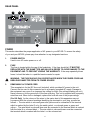
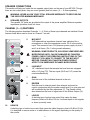
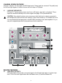
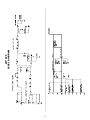
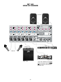
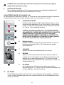
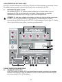
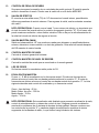
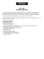
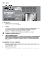
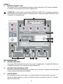
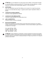
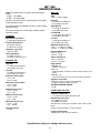
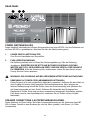
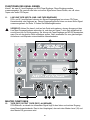
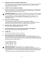
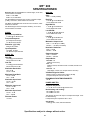
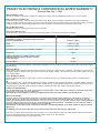
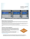
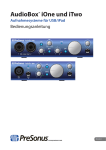
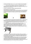
™
MP 600
Powered Mixer
Operating Guide
Intended to alert the user to the presence of uninsulated “dangerous voltage” within the product’s
enclosure that may be of sufficient magnitude to constitute a risk of electric shock to persons.
Intended to alert the user of the presence of important operating and maintenance (servicing)
instructions in the literature accompanying the product.
CAUTION: Risk of electrical shock — DO NOT OPEN!
CAUTION: To reduce the risk of electric shock, do not remove cover. No user serviceable parts inside. Refer
servicing to qualified service personnel.
WARNING: To prevent electrical shock or fire hazard, do not expose this appliance to rain or moisture. Before
using this appliance, read the operating guide for further warnings.
Este símbolo tiene el propósito, de alertar al usuario de la presencia de “(voltaje) peligroso” sin aislamiento dentro de la caja del producto y que puede tener una magnitud suficiente como para constituir
riesgo de descarga eléctrica.
Este símbolo tiene el propósito de alertar al usario de la presencia de instruccones importantes sobre la
operación y mantenimiento en la información que viene con el producto.
PRECAUCION: Riesgo de descarga eléctrica ¡NO ABRIR!
PRECAUCION: Para disminuír el riesgo de descarga eléctrica, no abra la cubierta. No hay piezas útiles dentro.
Deje todo mantenimiento en manos del personal técnico cualificado.
ADVERTENCIA: Para evitar descargas eléctricas o peligro de incendio, no deje expuesto a la lluvia o humedad
este aparato Antes de usar este aparato, Iea más advertencias en la guía de operación.
Ce symbole est utilisé dans ce manuel pour indiquer à l’utilisateur la présence d’une tension dangereuse
pouvant être d’amplitude suffisante pour constituer un risque de choc électrique.
Ce symbole est utilisé dans ce manuel pour indiquer à l’utilisateur qu’il ou qu’elle trouvera d’importantes
instructions concernant l’utilisation et l’entretien de l’appareil dans le paragraphe signalé.
ATTENTION: Risques de choc électrique — NE PAS OUVRIR!
ATTENTION: Afin de réduire le risque de choc électrique, ne pas enlever le couvercle. Il ne se trouve à l’intérieur
aucune pièce pouvant être reparée par l’utilisateur. Confiez I’entretien et la réparation de l’appareil à un réparateur
Peavey agréé.
AVERTISSEMENT: Afin de prévenir les risques de décharge électrique ou de feu, n’exposez pas cet appareil à la
pluie ou à l’humidité. Avant d’utiliser cet appareil, lisez attentivement les avertissements supplémentaires de ce
manuel.
Dieses Symbol soll den Anwender vor unisolierten gefährlichen Spannungen innerhalb des Gehäuses
warnen, die von Ausreichender Stärke sind, um einen elektrischen Schlag verursachen zu können.
Dieses Symbol soll den Benutzer auf wichtige Instruktionen in der Bedienungsanleitung aufmerksam
machen, die Handhabung und Wartung des Produkts betreffen.
VORSICHT: Risiko — Elektrischer Schlag! Nicht öffnen!
VORSICHT: Um das Risiko eines elektrischen Schlages zu vermeiden, nicht die Abdeckung enfernen. Es befinden
sich keine Teile darin, die vom Anwender repariert werden könnten. Reparaturen nur von qualifiziertem
Fachpersonal durchführen lassen.
ACHTUNG: Um einen elektrischen Schlag oder Feuergefahr zu vermeiden, sollte dieses Gerät nicht dem Regen
oder Feuchtigkeit ausgesetzt werden. Vor Inbetriebnahme unbedingt die Bedienungsanleitung lesen.
2
ENGLISH
MP™ 600
POWERED MIXER
Thank you for purchasing the Peavey MP™ 600! The MP™ 600 is a seven-channel mixer with a
variety of built-in features, including a dedicated line input channel (summed input for a tape deck
or other line level device), 32-bit digital reverb, channel and master equalizers and a 80 W power
amplifier, all housed in a rugged topbox package.
This owners manual explains the MP 600’s features and its proper operation. Each section of the
mixer is separated into numbered illustrations. In each illustration you will be directed to a controls’
explanation of operation by its corresponding reference number.
FEATURES:
•
•
•
•
•
•
•
•
•
•
•
•
Seven total input channels
Reverb control on each channel
Six mono input channels
One mono (summed) input channel with stereo RCA and 1/4" jacks
Two-band equalizer on each channel
1/4" and XLR inputs (Channels 1 — 6 only)
Master effects output (1/4" send jack)
Main output (1/4" send jack)
Master four-band equalizer
RCA tape record output (summed)
Master level and reverb controls
80 W power amp
3
REAR PANEL
3
2
1
4
POWER
This section describes the proper application of AC power to your MP 600. To ensure the safety
of you and your MP 600, please pay close attention to any designated cautions.
1.
POWER SWITCH
Used to turn AC mains power on or off.
2.
FUSE
The fuse is located within the cap of the fuseholder. If the fuse should fail, IT MUST BE
REPLACED WITH THE SAME TYPE AND VALUE IN ORDER TO AVOID DAMAGE TO THE
EQUIPMENT AND TO PREVENT VOIDING THE WARRANTY. If the amp repeatedly blows
fuses, it should be taken to a qualified service center for repair.
WARNING: THE FUSE SHOULD ONLY BE REPLACED WHEN THE POWER CORD HAS
BEEN DISCONNECTED FROM ITS POWER SOURCE.
3.
REMOVABLE AC POWER CORD
This receptacle is for the IEC line cord (included), which provides AC power to the unit.
Connect the line cord to this connector and to a properly grounded AC supply. Damage to
the equipment may occur if an improper line voltage is used. (See voltage marking on unit.)
Never remove or cut the ground pin of the line cord plug. This unit is supplied with a properly
rated line cord. When lost or damaged, replace this cord with one of the proper ratings.
(For UK Only) As the colours of the wires in the mains lead of this apparatus may not
correspond with the coloured markings identifying the terminals in your plug, proceed as
follows: • The wire which is coloured green and yellow must be connected to the terminal
which is marked by the letter E or by the earth symbol, or coloured green or green and
yellow. • The wire which is coloured blue must be connected to the terminal which is marked
with the letter N or coloured black. • The wire which is coloured brown must be connected
the terminal which is marked with the letter L or the coloured red.
4
SPEAKER CONNECTIONS
This section will help you locate the two speaker output jacks on the rear of your MP 600. Though
there are two output jacks, they are mono (parallel) and not stereo. (2 — 8 ohms speakers)
WARNING: NEVER ALLOW YOUR TOTAL SPEAKER IMPEDANCE TO DROP BELOW
THE INDICATED MINIMUM IMPEDANCE.
4.
SPEAKER OUTPUTS
Two parallel 1/4" jacks are provided at the output of the power amplifier. Minimum speaker
impedance (minimum load) is 4 ohms.
.
CHANNEL (1— 6) FEATURES
The following section describes Channels 1 — 6. Each of these input channels are identical. Some
features listed below can be found on Channel 7 as well.
5.
10
WARNING: SOME PRODUCTS, INCLUDING SOME WIRELESS
MICROPHONE UNITS, CAN BE DAMAGED BY PHANTOM
POWER. CHECK THE OPERATING INSTRUCTIONS OF THE
PRODUCT YOU WISH TO CONNECT TO THE MIC INPUT
BEFORE CONNECTING. PHANTOM POWER DOESN’T
AFFECT LOW IMPEDANCE DYNAMIC MICROPHONES.
9
8
6.
LINE INPUT
1/4" unbalanced input that accepts line level sources equipped
with a 1/4" plug (TS). The two inputs (XLR and 1/4") cannot be
used simultaneously.
7.
GAIN
Sets the level of the individual channel in the mix.
8.
REVERB
Sets the level to internal reverb from channel and must be
used in conjunction with the master reverb level. It is post gain and
will be affected by the Gain adjustment (7). The Reverb control
also determines the level of signal sent to the Effects Output (14).
9.
LOW EQ
A shelving type of active tone control that varies the bass
frequency levels ±15 dB at 100 Hz. It will add depth to thin signals,
or clean up muddy ones.
7
6
5
10.
MIC INPUT
XLR balanced low impedance channel input optimized for a
microphone or other low impedance source. Pin 2 is the positive
input. This connector has +15V phantom power supply on pins 2
and 3 at all times. (Pin 1 is the ground reference.)
HIGH EQ
A shelving type of active tone control that varies the treble frequency level ±15 dB at 10 kHz.
It is designed to remove noise or to add brilliance to the signal, depending on the quality of
the source.
5
CHANNEL SEVEN FEATURES
Channel 7 has two 1/4" line inputs and RCA tape inputs. These inputs are summed. They add (sum)
the left and right signals of a stereo source such as a tape or CD player.
11.
LINE AND TAPE INPUTS
RCA and 1/4" jacks accept a stereo input from a CD player, tape deck or keyboard. These
inputs are summed internally into a mono signal. See page 10 for operational note.
CAUTION: Care should be taken not to record on a deck that has its outputs connected to
the line/tape input jacks and have the Channel 7 Gain control turned up, or Feedback will occur.
You may disconnect the tape inputs on the MP 600 if recording on the same tapedeck. Or, you
may use a separate tape deck to play and record at the same time.
19
18
16
17
11
12 13
14
15
MASTER FEATURES
12.
TAPE [REC] OUTPUTS
RCA output jacks that provide a monaural signal to the left and right inputs of a stereo tape
deck. This is the main signal taken after the Master Level (16) and the Master EQ.
6
13.
REVERB FOOTSWITCH
Provided for connection of the optional remote footswitch. The footswitch is used to
activate/defeat the reverb. You may use the ON/OFF single-button switch #0051000.
14.
EFFECTS OUTPUT
Plugging into this mono (TS) 1/4" output disconnects the internal reverb, allowing you to
utilize external effects devices. In order to return the signal from the external effects unit, use
the summing inputs of Channel 7.
OPERATION NOTE: When using Channel 7 as an effects return, it is important that you turn
the Channel 7 Reverb control all the way down (“0” position). Failure to do so may cause
oscillation or other strange effects. This is due to feeding signal returned from the effects loop
back into the effects loop resulting in a feedback.
15.
MAIN OUTPUT
1/4" unbalanced output that can be used as a source for an external amplifier/speaker
system, feed to other mixers or a tape deck. This signal is taken after the master fourband equalizer.
16.
MASTER LEVEL CONTROL
Controls the overall volume level of the system.
17.
MASTER REVERB LEVEL CONTROL
Controls the amount of reverb that will be heard in the main mix.
18.
POWER LED
Illuminates when AC power is being supplied to the mixer.
19.
MASTER EQUALIZATION
Provides ±12 dB equalization at each center frequency. EQ boost is obtained by moving a
particular EQ band’s control above the “0” position. EQ cut is obtained by moving a particular
EQ band’s control below the “0” position. The following list describes each EQ control and its
center frequency.
Low - shelving type - 40 Hz
Low Mid - peak type - 300 Hz
High Mid - peak type - 2 kHz
High - shelving type - 10 kHz
OPERATION NOTE: This equalizer is designed to provide room equalization, feedback
control and system tone control. No amount of equalization will correct the response curve of
a poor loudspeaker. Always begin with all controls in the “0” position and avoid excessively
boosting large segments of the audio passband, which could limit the system’s dynamic
range.
7
MP™ 600
SPECIFICATIONS
NOTE: All specifications are typical unless otherwise
noted.
0 dBV = 1 Volt RMS
0 dBu = .778 Volts RMS
MASTER:
Gain:
Main: = 10 dB (variable)
High EQ:
All specs are referenced to nominal output level (0 dBv)
unless otherwise noted.
± 12 dB @ 10 kHz Minimum
Center Detent flat ±2 dB
All measurements are wideband 20 Hz to 20 kHz unless
otherwise noted.
High Mid EQ:
± 12 dB @ 2 kHz Minimum
Center Detent flat ±2 dB
All control settings are nominal (50% rotation) unless
otherwise noted.
Low Mid EQ:
± 12 dB @ 300 kHz Minimum
Center Detent flat ±2 dB
CHANNEL:
Equivalent Input Noise:
Low EQ:
-114 dBu @ 40 dB Max Gain
± 12 dB @ 40 HZ Minimum
Center Detent flat ±2 dB
Frequency Response:
Maximum Output Level:
(To Speaker Outputs)
± 3 dB 20 Hz to 20 kHz
Main: = + 20 dBu (8.0 V RMS)
Effects: = + 20 dBu (8.0 V RMS)
Distortion: @ (1 kHz)
Nominal Headroom:
Less than .009%
Main: = 18 dB
Effects: = 18 dB
Input Impedance:
Low Z Bal. 2K ohms
1/4" Mic/Line Input 22K ohms
Output Impedance:
Main: = 100 ohms
Effects: = 100 ohms
CHANNEL EQ:
Output Noise:
High EQ:
Residual: -93 dBu
(Master Level Down)
Bus: -91 dBu
(Master Nominal, All Channel Level Full CCW, Reverb Level
Down)
Nominal: -76 dBu
(All Controls Nominal, Low Z Input Terminated 150 Ohms)
± 15 dB @ 10 kHz Minimum
Center Detent flat ±2 dB
Low EQ:
± 15 dB @ 100 Hz Minimum
Center Detent flat ±2 dB
Nominal Channel Gain:
Line = 0 dB
Low Z = 30 dB
Signal to noise ratio:
Microphone input to speaker output (>80 dB)
Frequency Response: 20 Hz to 20 kHz
Maximum Channel Gain:
Low Z = 50 dB
Line = 19 dB
SYSTEM DYNAMIC RANGE:
95 dB
Nominal Input Level:
POWER AMP SECTION:
Low Z = -28 dBu
Line = +2 dBu
Frequency Response:
Minimum Input Level:
+0, -3 dB, 30 Hz to 28 kHz @ Rated Power
Low Z = -48 dBu
Line = -17 dBu
Rated Power and Load:
80 W RMS into 4 ohms
55 W RMS into 8 ohms
Maximum Input Level:
Low Z = -9 dBu
Line = +30 dBu
THD less than .5% Mic input to speaker output 1 kHz at rated
power.
Phantom Power:
Speaker system Impedance: 4 ohms minimum.
+15 VDC
Power Requirements:
150W @ 100V, 120V, 230 VAC 50/60 Hz
Specifications subject to change without notice.
8
9
MP™ 600
LEVEL DIAGRAM
MP™ 600
HOOK UP DIAGRAM
112 TLS™
Outputs on back
L
Preamp out
Out
In
R
Effects Unit
PVM® 22
L
Out
R
Tape Deck*
TKO™ 115s
*Tape deck and Effects Unit should
not be connected at the same time.
Both are shown for demonstration
purposes only.
10
ESPAÑOL
MP™ 600
MEZCLADORA AMPLIFICADA
Gracias por comprar la mezcladora Peavey MP 600. La MP 600 es una mezcladora de siete
canales con una variedad de características incluidas, incluyendo un canal de entrada dedicada a
niveles de línea (entrada sumada para un deck de cinta u otro aparato de nivel de línea), reverb
digital de 32 bits, ecualizadores de canales y maestros, y un amplificador de 80 wats, todo dentro
de una caja sólida.
Este manual del usuario explica las características de la MP 600, así como su operación. Cada
sección de la mezcladora ha sido separada en ilustraciones numeradas. En cada ilustración serás
dirigido a una explicación de los controles por medio de su numero de referencia correspondiente.
CARACTERÍSTICAS
•
•
•
•
•
•
•
•
•
•
•
•
Siete canales de entrada totales
Control de reverb en cada canal
Seis canales de entrada mono
Un canal de entrada mono (sumado) con conexiones RCA y 1/4" estéreo
Ecualizador de dos bandas en cada canal
Entradas de 1/4" y XLR (Canales 1-6 solamente)\
Entrada maestra de efectos (envío de 1/4")
Salida maestra (envío de 1/4")
Ecualizador maestro de cuatro bandas
Salida de grabación a cinta RCA (sumada)
Controles maestros de nivel y de reverb
Amplificador de poder de 80 wats
11
REAR PANEL
3
2
1
PODER
Esta sección describe la aplicación correcta de poder CA a tu MP 600. Para asegurar tu seguridad y
la de tu MP 600, por favor presta atención a todas las precauciones indicadas.
1.
SWITCH DE PODER
Se usa para encender o interrumpir la corriente.
2.
FUSIBLE
El fusible está localizado dentro de la tapa del receptáculo para el fusible. Si el fusible falla,
TIENE QUE SER REEMPLAZADO POR UNO DE LAS MISMAS MEDIDAS Y VALORES
PARA EVITAR DAÑOS AL EQUIPO Y MANTENER LA GARANTÍA VÁLIDA. Si el amp
funde fusibles repetidamente, debe ser llevado a un centro de servicio calificado para que la
reparen.
CUIDADO: EL FUSIBLE SÓLO DEBE SER REEMPLAZADO CUANDO EL CABLE DE
CORRIENTE HA SIDO DESCONECTADO DE LA PARED.
3.
CABLE REMOVIBLE DE CORRIENTE ALTERNA.
Este conector es para el cable de línea IEC (incluido), que proporciona poder CA a la unidad.
Conecta el cable de línea a este conector y a un suministro de corriente alterna propiamente
aterrizado. Puede ocurrir daño al equipo si un voltaje incorrecto es usado (ver marcación de
voltaje en la unidad). Nunca quites o cortes el alfiler de tierra del cable de línea. Esta unidad
trae un cable propiamente clasificado. Si se pierde o se daña, reemplázalo con uno que
tenga las especificaciones correctas.
CONEXIONES DE BOCINAS
Esta sección te ayudará a localizar las dos conexiones de salidas de bocinas en la parte
trasera de tu MP 600. Aunque hay dos salidas, estas son mono (paralelas) y no estéreo.
(bocinas de 2-8 ohmios)
12
CUIDADO: Nunca permitas que el total de la impedancia de las bocinas caiga por
debajo de la impedancia mínima.
4.
SALIDAS DE BOCINAS
Dos conexiones paralelas de 1/4" son proporcionadas como salidas del amplificador. El
mínimo de impedancia para las bocinas debe ser 4 ohmios.
CARACTERÍSTICAS DE LOS CANALES (1-6)
La siguiente sección describe los canales 1-6. Cada una de estas entradas es idéntica. Algunas de
las características aquí mencionadas también pueden ser encontradas en el canal 7.
5.
10
CUIDADO: ALGUNOS PRODUCTOS, INCLUYENDO MICROS
INALAMBRICOS, PUEDEN SER DAÑADOS POR EL PHANTOM
POWER. REVISA LOS INSTRUCTIVOS DE CUALQUIER
PRODUCTO QUE QUIERAS CONECTAR A LA ENTRADA DE
MICRO ANTES DE HACER LA CONEXIÓN. El poder phantom
no afecta micros dinámicos de baja impedancia.
9
8
6.
Entrada de línea
Entrada no balanceada de 1/4" que acepta fuentes con nivel de
línea. Las dos entradas (XLR y 1/4") no pueden ser usadas
simultáneamente.
7.
GANANCIA
Ajusta el nivel del canal independiente en la mezcla.
8.
REVERB
Ajusta el nivel al reverb interno del canal y debe ser usado en
conjunto con el nivel maestro de reverb. Es post ganancia y será
afectado por los ajustes de ganancia (7). El control de reverb
también determina la cantidad de nivel de señal que se envía a la
salida de efectos (14).
9.
EQ GRAVE
Un ecualizador tipo ‘shelving’ de tono activo que varía las
frecuencias graves +/- 15 dB en 100 Hz. Añadirá profundidad a las
señales delgadas, y limpiara las lodosas.
7
6
5
10.
ENTRADA DE MICRO
Entrada de baja impedancia XLR optimizada para micros u otras
fuentes de baja impedancia. El pin 2 es el positivo. Este conector
cuenta con fuente de poder phantom power constante en los pins
2 y 3 (el pin 1 es la referencia de tierra).
EQ AGUDO
Un ecualizador tipo ‘shelving’ de tono activo que varía las frecuencias agudas +/- 15 dB en
10 kHz. Ha sido diseñado para quitar ruido y añadir brillantez a la señal, dependiendo de la
calidad de la fuente.
13
CARACTERÍSTICAS DEL CANAL SIETE
El canal 7 tiene dos entradas de 1/4"de línea y RCA de cinta. Estas entradas son sumadas. Suman
las señales estéreo izquierda y derecha de la fuente como un reproductor de CDs.
11.
ENTRADAS DE LÍNEA Y CINTA
Las entradas de RCA y 1/4" estéreo aceptan señales de una fuente estéreo como un
reproductor de CDs, un deck de cintas o un teclado. Estas entradas son sumadas
internamente a una señal mono, ver pag. 10 para una nota operacional.
CUIDADO: Se debe tener cuidado de no grabar a un deck que tiene las salidas conectadas
al canal 7 y con la ganancia subida, ya que resultará en retroalimentación. Puedes
desconectar las entradas de cinta en la MP 600 si estás grabando al mismo deck. O, puedes
usar un deck diferente para grabar y reproducir simultáneamente.
19
18
16
17
11
12 13
14
15
CARACTERÍSTICAS MAESTRAS
12.
SALIDAS DE CINTA (REC)
La MP 600 cuenta con salidas RCA que proporcionan una señal monoaural a las entradas
derecha e izquierda de un deck de grabación. Esta es la señal maestra después de pasar
por el nivel maestro (16) y el EQ maestro.
14
13.
CONTROL DE PEDAL DE REVERB
Se proporciona para la conexión de un controlador de pedal opcional. El pedal te permite
activar o desactivar el reverb. Puedes usar el switch de un sólo botón #0051000.
14
SALIDA DE EFECTOS
El conectar a esta salida mono (TS) de 1/4" desconecta el reverb interno, permitiéndote
utilizar procesadores de sonido externos. Para regresar la señal, usa las entradas sumarias
del canal 7.
NOTA OPERACIONAL: Cuando uses el canal 7 como retorno de efectos, es importante que
el nivel de control del reverb esté en la posición de apagado (posición "0"). El no hacer esto
puede ocasionar oscilación u otros efectos extraños. Esto se da por la retroalimentación de
la señal del circuito de efectos de regreso al circuito.
15.
SALIDA MAESTRA (MAIN)
Salida no balanceada de 1/4" que puede ser usada para alimentar un amplificador/bocina
externa, alimentar a otras consolas o un deck de grabación. Esta señal es tomada después
del EQ maestro de cuatro bandas.
16.
CONTROL MAESTRO DE NIVEL
Controla el volumen general del sistema.
17.
CONTROL MAESTRO DE NIVEL DE REVERB
Controla la cantidad de reverb que se escuchará en la mezcla general.
18.
LED DE PODER
Se ilumina cuando la mezcladora recibe poder de CA.
19.
ECUALIZACIÓN MAESTRA
Provee +/- 12 dB de ecualización en la frecuencia central. El realce de frecuencias se
obtiene al mover el control de una banda particular arriba de la posición “0”. El corte de
frecuencias se obtiene al mover el control de una banda encima de la posición “0”. La lista
siguiente describe cada control del ecualizador y su frecuencia central.
Grave - tipo shelving - 40 Hz
Medio Grave- tipo pico - 300 Hz
Medio Agudo – 2 kHz
Agudo – 10 kHz
NOTA OPERACIONAL: Este ecualizador está diseñado para proveerte ecualización de sala,
control de retroalimentación y sistema de control de tono. Ninguna curva de ecualización
resolverá los problemas de un sistema de bocinas de baja calidad. Siempre comienza con
los controles en la posición “0” y manténte alejado de amplificación excesiva de ciertos
segmentos de las bandas de audio, lo que limita el rango dinámico del sistema.
15
MP 600
ESPECIFICACIONES
NOTA: Todas las especificaciones son típicas, a menos que se
indique de otra forma.
0 dBv= 1 Voltio RMS
0 dBu= .778 Voltios RMS
MASTER:
Ganancia:
Main: = 10 dB (variable)
EQ agudo:
Todas las especificaciones se referencían a nivel de salida
nominal (0dBv) a menos que se indique de otra forma.
+/- 12 dB @ 10 kHz mínimo
retén mínimo central +/- 2 dB
Todas las medidas se hacen de 20 HZ a 20 kHz a menos que se
indique de otra forma.
EQ agudo medio:
+/- 12 dB @ 2 kHz mínimo
retén mínimo central +/- 2 dB
Todos los controles son nominales (rotación de 50%) a menos
que se indique de otra forma.
EQ medio grave:
+/- 12 dB @ 300 Hz mínimo
retén mínimo central +/- 2 dB
CANAL
Ruido de entrada equivalente:
EQ grave:
-116 dBv @ 40 dB Ganancia máxima
+/- 12 dB @ 40 Hz mínimo
retén mínimo central +/- 2 dB
Respuesta de frecuencias:
(a salidas de bocinas)
+/- 3 dB 20 Hz a 20 kHz
Nivel de salida máximo:
Main: = +18 dBv (8.0 V RMS)
Efectos: = 18 dBv (8.0 V RMS)
Distorsión: @ (1kHz)
Menos de .009%
Umbral nominal:
Impedancia de entrada:
Main: = 18 dB
Efectos: = 18 dB
Low Z Bal. 2k ohmios
Entrada línea/micro de 1/4" 22k ohmios
Impedancia de salida:
Main: = 100 ohmios
Efectos: = 100 ohmios
CANAL DE ECUALIZACIÓN:
EQ Agudo:
Ruido de salida:
+/- 15 dB @ 10 kHz
retén mínimo central +/- 2 dB
Residuos: -95
(nivel maestro abajo)
Bus: -93
Maestro nominal. Todos los canales a tope, reverb abajo)
Nominal: -78
(Todos los controles nominales, entrada Low Z terminada
150 ohmios)
EQ Grave:
+/- 15 dB @ 100 Hz
retén mínimo central +/- 2 dB
Ganancia nominal de canal:
Línea = 0 dAB
Low Z = 30 dB
Razón ruido/ señal
Ganancia máxima de canal:
Entrada de micro a salida de bocina (>80 dB)
Respuesta de frecuencias: 20 Hz a 20 kHz
Low Z = 50 dB
Línea = 19 dB
RANGO DINÁMICO DEL SISTEMA:
Ganancia nominal de entrada
95 dB
Línea = 0dAB
Low Z = -30 dB
SECCIÓN DEL AMPLIFICADOR:
Respuesta de frecuencias:
+0, -3 dB, 30 Hz a 28 kHz @ poder controlado (rated power)
Ganancia máxima de entrada:
Low Z = -50 dB
Línea = 19 dB
Poder controlado y cargo (load)
80 W RMS a 4 ohmios
55 W RMS a 8 ohmios
Nivel mínimo de entrada:
Low Z = -50 dB
Línea = -19 dB
THD menos de .5%. Entrada de micro a salida de bocina 1 kHz
a poder controlado
Nivel máximo de entrada:
Impedancia de sistema de bocinas: 4 ohmios mínimo
Low Z = -11 dB
Línea = +28 dB
Poder Phantom:
+ 15 VDC
Requisitos de poder:
150 W @ 100 V, 120 V, 230 VAC 50/60 Hz
Specifications subject to change without notice.
16
FRANÇAIS
MP™ 600
MIXEUR AMPLIFIE
Nous vous félicitons pour l’achat de ce Peavey MP™ 600. Le MP™ 600 est une table de mixage
amplifiée comportant 7 canaux et de multiples fonctions: un canal avec entrée ligne (entrées
sommées pour lecteurs de cassettes ou toute source de niveau ligne), une réverbe numérique 32
bit, des équalisations par canal et master, et un étage de puissance de 80 W.
Ce manuel explique toutes les fonctionnalités de la MP 600 et leur mode d’utilisation pour que vous
puissiez en tirer au maximum.
CARACTERISTIQUES:
•
•
•
•
•
•
•
•
•
•
•
•
Sept canaux au total
Réverbe sur chaque canal
Six canaux à entrée mono
Un canal mono (entrées sommées) pour les sources stéréos avec entrées RCA et Jack
Equalisation 2 bandes sur chaque canal
Entrées Jack et XLR (Canaux 1 à 6 uniquement)
Sortie effets master (Jack)
Sortie Main ( Jack)
Equalisation Master 4 bandes
Sortie enregistrement RCA (sommée)
Contrôles de niveau et de réverbe Master
Puissance de 80 W
17
REAR PANEL
3
2
1
ALIMENTATION
1.
INTERRUPTEUR D’ALIMENTATION
Permet la mise sous tension de la MP600.
2.
FUSIBLE
Ce fusible est connecté à l’alimentation principale. Ne remplacez le fusible que par un modèle du même type et de même valeur. SI LE FUSIBLE GRILLE CONSTAMMENT,
APPORTEZ L’APPAREIL À UN RÉPARATEUR PEAVEY AGRÉÉ.
ATTENTION: NE REMPLACEZ CE FUSIBLE QUE LORSQUE LE CABLE
D’ALIMENTATION EST DECONNECTE.
3.
CORDON D’ALIMENTATION IEC
Prise pour cordon d’alimentation IEC, fournissant l’électricité au mixeur amplifié. Branchez le
cordon d’alimentation pour mettre la console sous tension. L’équipement peut être endommagé si une tension d’alimentation incorrecte est utilisée (voir les spécifications de tension
sur l’appareil).
CONNEXIONS DES HAUT-PARLEURS
ATTENTION: L’IMPÉDANCE TOTALE EN SORTIE DE L’AMPLIFICATEUR NE DOIT PAS
ETRE INFERIEURE À 4 OHM.
4.
SORTIES HAUT-PARLEUR
Deux sorties Jack permettent la connexion des haut-parleurs. L’impédance minimum totale
est de 4 Ohm.
.
18
CANAUX 1 A 6
Certaines des caractéristiques et fonctionnalités des canaux 1 à 6 s’appliquent aussi au canal 7.
5.
ENTREE MICRO
Cette entrée XLR est optimisée pour les micros et autres sources basses impédances. La
borne 2 est l’entrée positive. L’alimentation Phantom (+15V) est appliquée aux bornes 2 et 3
en permanence (la borne 1 est à la masse).
ATTENTION: NE CONNECTEZ PAS DE MICROS ASYMÉTRIQUES OU D’AUTRES
APPAREILS NE SUPPORTANT PAS LA TENSION DE L’ALIMENTATION PHANTOM AUX
CONNECTEURS XLR (CERTAINS APPAREILS SANS FIL PEUVENT ÊTRE
ENDOMMAGÉS, CONSULTEZ D’ABORD LEUR NOTICE D’UTILISATION).
6.
ENTREE LINE
Cette entrée Jack accepte les signaux des sources asymétriques de niveau Ligne. Les
entrées Jack et XLR ne peuvent être utilisées simultanément.
7.
GAIN
Détermine le niveau du canal dans le mix.
8.
REVERBE
Détermine le niveau de l’effet pour le canal concerné et doit être utilisé en conjonction avec le
réglage de réverbe master. Ce contrôle est situé aprés le contrôle de gain (8) et sera affecté
par son réglage. Il détermine par ailleur le niveau du signal envoyé à la sortie Effects (14).
9.
LOW EQ
Réglage de tonalité actif permettant de modifier les niveaux des basses fréquences de
+/-15 dB à 100 Hz. Elle permet également de donner de la profondeur aux sons trop fins et
d’éclaircir les sons confus
10.
HIGH EQ
Réglage de tonalité actif permettant de modifier les niveaux de hautes fréquences de
+/-15 dB à 10 kHz. Cette égalisation est conçue pour éliminer le bruit ou ajouter de la
brillance au signal, suivant la qualité de la source sonore.
19
CANAL 7
11.
ENTREES LIGNE ET TAPE
Ces entrées RCA et Jack acceptent les signaux stéréos de lecteurs CD, lecteurs cassettes
ou claviers et les somme pour en faire un signal mono.
ATTENTION: ne reliez pas les connecteurs TAPE IN et TAPE OUT aux entrées et sorties du
même lecteur sous risque de créer un important larsen. Utilisez deux appareils distincts pour
le playback et l’enregistrement.
19
18
16
17
11
12 13
14
15
SECTION MASTER
12.
SORTIES TAPE [REC]
Ces sorties RCA fournissent une sortie mono pour l’enregistrement. Le signal est affecté par
l’équalisation générale et le contrôle de niveau Master (16).
13.
INTERRUPTEUR REVERB AU PIED
Permet la connexion d’une pédale de commande pour la réverbe. L’utilisation de l’interrupteur
Peavey référence 0051000 est conseillée.
14.
SORTIE EFFETS
En connectant un Jack à cette sortie, vous déconnecterez la réverbe interne et pourrez
utilisez des effets externes. Le retour de l’effet se fera par les entrées du canal 7 ou l’entrée
ligne d’un autre canal.
20
ATTENTION: Lors de l’utilisation d’un canal comme retour d’effets, il est important de régler
son contrôle d’effets au minimum (position “0”). Si cette règle n’est pas appliquée, un larsen
important surviendra pouvant endommager l’appareil ou vos haut-parleurs.
15.
SORTIE MAIN
Sortie Jack asymétrique pouvant être utilisée pour la connexion à un ampli de puissance
externe ou une autre table de mixage. Le signal est prélevé aprés l’équalisation Master 4
bandes .
16.
CONTROLE DE NIVEAU MASTER
Contrôle le volume générale de la MP600.
17.
CONTROLE DE REVERBE MASTER
Contrôle le niveau générale de la réverbe dans le mix
18.
LED D’ALIMENTATION
S’illumine lorsque le mixeur est alimenté.
19.
EQUALISATION MASTER
Permet des corrections de ±12 dB à chaque centre des bandes de fréquence. En position
centrale, la bande de fréquence n’est pas affectée. La liste suivante indique le type de filtre et
sa fréquence de centrage:
Low - type shelving - 40 Hz
Low Mid - type peak - 300 Hz
High Mid - type peak - 2 kHz
High - type shelving - 10 kHz
ATTENTION: Cette équalisation est destinée à corriger la réponse de la pièce dans laquelle
est installé le système. Commencez toujours avec les contrôles à “0” et évitez de booster les
fréquences afin de ne pas limiter la marge dynamique de l’étage de puissance et le marge de
puissance avant larsen.
21
MP™ 600
SPECIFICATIONS
NOTE: All specifications are typical unless otherwise
noted.
0 dBv = 1 Volt RMS
0 dBu = .778 Volts RMS
MASTER:
Gain:
Main: = 10 dB (variable)
High EQ:
All specs are referenced to nominal output level (0 dBv)
unless otherwise noted.
± 12 dB @ 10 kHz Minimum
Center Detent flat ±2 dB
All measurements are wideband 20 Hz to 20 kHz unless
otherwise noted.
High Mid EQ:
± 12 dB @ 2 kHz Minimum
Center Detent flat ±2 dB
All control settings are nominal (50% rotation) unless
otherwise noted.
Low Mid EQ:
± 12 dB @ 300 kHz Minimum
Center Detent flat ±2 dB
CHANNEL:
Equivalent Input Noise:
Low EQ:
-116 dBv @ 40 dB Max Gain
± 12 dB @ 40 HZ Minimum
Center Detent flat ±2 dB
Frequency Response:
Maximum Output Level:
(To Speaker Outputs)
± 3 dB 20 Hz to 20 kHz
Main: = + 18 dBv (8.0 V RMS)
Effects: = + 18 dBv (8.0 V RMS)
Distortion: @ (1 kHz)
Nominal Headroom:
Less than .009%
Main: = 18 dB
Effects: = 18 dB
Input Impedance:
Low Z Bal. 2K ohms
1/4" Mic/Line Input 22K ohms
Output Impedance:
Main: = 100 ohms
Effects: = 100 ohms
CHANNEL EQ:
Output Noise:
High EQ:
Residual: -95
(Master Level Down)
Bus: -93
(Master Nominal, All Channel Level Full CCW, Reverb Level
Down)
Nominal: -78
(All Controls Nominal, Low Z Input Terminated 150 Ohms)
± 15 dB @ 10 kHz Minimum
Center Detent flat ±2 dB
Low EQ:
± 15 dB @ 100 Hz Minimum
Center Detent flat ±2 dB
Nominal Channel Gain:
Line = 0 dB
Low Z = 30 dB
Signal to noise ratio:
Microphone input to speaker output (>80 dB)
Frequency Response: 20 Hz to 20 kHz
Maximum Channel Gain:
Low Z = 50 dB
Line = 19 dB
SYSTEM DYNAMIC RANGE:
95 dB
Nominal Input Level:
POWER AMP SECTION:
Low Z = -30 dB
Line = 0 dB
Frequency Response:
Minimum Input Level:
+0, -3 dB, 30 Hz to 28 kHz @ Rated Power
Low Z = -50 dB
Line = -19 dB
Rated Power and Load:
80 W RMS into 4 ohms
55 W RMS into 8 ohms
Maximum Input Level:
Low Z = -11 dB
Line = +28 dB
THD less than .5% Mic input to speaker output 1 kHz at rated
power.
Phantom Power:
Speaker system Impedance: 4 ohms minimum.
+15 VDC
Power Requirements:
150W @ 100V, 120V, 230 VAC 50/60 Hz
Specifications subject to change without notice.
22
DEUTSCH
MP™ 600
POWER MIXER
Herzlichen Glückwunsch zum Kauf des Peavey MP™ 600! Der MP™ 600 ist ein SiebenkanalMischpult mit vielen Funktionen, unter anderem einem Line-Input Kanal (kombinierter Eingang für
ein Kassettendeck oder ein anderes Gerät), 32-bit digital Reverb, Kanal- und Master-Regler und
einem 80 W-Verstärker, alles zusammen untergebracht in einer widerstandsfähigen Topbox.
Diese Gebrauchsanleitung erklärt die Funktionen des MP 600 und seinen fachgerechten Betrieb.
Jedes Teil des Mixers wird in durchnummerierten Abbildungen dargestellt. In jeder Abbildung werden
Sie über entsprechende Referenznummern auf die Erklärung der Funktionen verwiesen.
FUNKTIONEN:
• Sieben Input-Eingänge
• Reverb-Regler auf jedem Kanal
• Sechs Mono-Eingänge
• Ein Mono-Eingang mit Stereo RCA und 6,3 mm Buchsen
• Zwei-Band-Equalizer auf jedem Kanal
• 6,3 mm und XLR-Eingänge (nur Kanal 1 - 6)
• Master-Effekte Ausgang (6,3 mm Send-Buchse)
• Hauptausgang (6,3 mm Send-Buchse)
• Master Vier-Band-Equalizer
• RCA Tape-Aufnahme-Ausgang (kombiniert)
• Master Level- und Reverb-Regler
• 80 W-Verstärker
23
REAR PANEL
3
2
1
POWER (NETZANSCHLUSS)
Dieser Abschnitt beschreibt den richtigen Stromanschluss an Ihren MP 600. Um Ihre Sicherheit und
die Ihres MP 600 zu gewährleisten, beachten Sie bitte alle Warnhinweise genau.
1.
POWER SWITCH (NETZSCHALTER)
Zum Ein-und Ausschalten der Stromzufuhr.
2.
FUSE (GERÄTESICHERUNG)
Die Sicherung befindet sich im Deckel der Sicherungshalterung. Falls die Sicherung
durchbrennt, ERSETZEN SIE SIE BITTE NUR MIT EINER SICHERUNG GLEICHEN
WERTES UND TYPS, UM SCHÄDEN AM GERÄT UND DEN VERFALL DER GARANTIE
ZU VERMEIDEN. Sollte die Sicherung öfter durchbrennen, lassen Sie das Gerät in einem
Peavey Service Center reparieren.
WARNUNG: DIE SICHERUNG NUR BEI GEZOGENEM NETZSTECKER AUSTAUSCHEN.
3.
REMOVABLE AC POWER CORD (ABNEHMBARES NETZKABEL)
Dieser Eingang ist für das (mitgelieferte) Netzkabel vorgesehen. Verbinden Sie das Kabel mit
dem Eingang und einem richtig geerdeten Wechselstromanschluss. Beim Anlegen der
falschen Netzspannung besteht die Gefahr, dass das Gerät beschädigt wird (beachten Sie
die Spannungsangabe auf dem Gerät). Entfernen Sie keinesfalls den Erdungspol des
Netzsteckers. Dieses Gerät wird mit einem entsprechend ausgelegten Netzstecker geliefert.
Falls dieser verloren oder beschädigt wird, verwenden Sie nur Ersatz mit den richtigen
Merkmalen.
SPEAKER CONNECTIONS (LAUTSPRECHERANSCHLÜSSE)
Dieser Abschnitt soll Ihnen helfen, die beiden Lautsprecherbuchsen auf der Hinterseite Ihres MP
600 zu finden. Obwohl es zwei Buchsen gibt, sind sie Mono (parallel), nicht Stereo. (2-8 Ohm
Lautsprecher)
24
Achtung: Die Gesamt-Lautsprecher-Impedanz darf nie das angegebene Minimum
unterschreiten.
4.
SPEAKER OUTPUTS (LAUTSPRECHERAUSGÄNGE)
Am Verstärkerausgang sind zwei parallele 6,3 mm-Buchsen angebracht. Minimal-Impedanz
für Lautsprecher ist 4 Ohm.
KANAL (1 — 6) FUNKTIONEN
Der folgende Abschnitt beschreibt die Kanäle 1 — 6. Diese Eingangskanäle sind alle gleich. Einige
der unten angeführten Funktionen treffen auch auf Kanal 7 zu.
5.
10
MIC INPUT (MIC-EINGANG)
Dies ist ein symetrischer XLR Low-Eingang, optimiert für
Mikrofone oder andere Quellen mit niedriger Impedanz.
2 = +. Dieser Anschluss hat immer +15V Phantom Power
an Pin 2 und 3. Pin 1= Erde.
9
ACHTUNG: MANCHE ARTIKEL, AUCH EINIGE
SCHNURLOSE MIKROFONE, KÖNNEN DURCH
PHANTOM POWER BESCHÄDIGT WERDEN.
BEACHTEN SIE VOR DEM ANSCHLUSS DIE
GEBRAUCHSANWEISUNG DES ARTIKELS, DEN SIE AM
MIC-EINGANG ANSCHLIESSEN WOLLEN. Phantom
Power hat keinen Einfluss auf dynamische Mikrofone
mit niedriger Impedanz.
8
7
6.
Line input (Line-Eingang)
6,3 mm asymetrische Buchse für Line-Level Quellen mit
6,3 mm Klinken-Stecker (TS). Die beiden Eingänge (XLR
und 6,3 mm) können nicht gleichzeitig benutzt werden.
7.
GAIN
Stellt das Niveau der einzelnen Kanäle beim Mischen ein.
8.
REVERB
Stellt den Level auf internen Hall vom Kanal und muss in
Verbindung mit dem Master Reverb-Level verwendet
werden. Es kommt nach dem Gain und wird über die
Einstellung des Gain (8) beeinflusst. Der Reverb-Regler
bestimmt auch den Level eines Signals, das an den EffektAusgang (14) gesendet wird.
6
5
9.
LOW EQ
Die Bandbreite kann um 15 dB (bei 100 Hz) angehoben oder abgesenkt werden. Ein dünnes
Signal kann voluminöser gemacht und ein basslastiges Signal ausgedünnt werden.
10.
HIGH EQ
Die Bandbreite kann um 15 dB (bei 10 kHz) angehoben oder abgesenkt werden. Abhängig
von der Tonquelle kann Rauschen entfernt oder mehr Brillanz hinzugefügt werden.
25
FUNKTIONEN DES KANAL SIEBEN
Kanal 7 hat zwei 6,3 mm-Eingänge und RCA-Tape-Eingänge. Diese Eingänge werden
zusammengelegt. Sie vereinen das linke und rechte Signal einer Stereo-Quelle, wie z.B. eines
Tapes oder eines CD-Players.
11.
LINE UND TAPE INPUTS (LINE- UND TAPE-EINGÄNGE)
RCA- und 6,3 mm-Buchsen nehmen ein Stereo-Eingangssignal von einem CD-Player,
Kassettendeck oder Keyboard an. Dieses Eingangssignal wird intern zu einem Mono-Signal
zusammengefasst. Auf Seite 10 finden Sie Bedienungshinweise.
VORSICHT: Achten Sie darauf, nicht auf ein Gerät aufzunehmen, dessen Ausgang mit den
Line/Tape-Eingangsbuchsen verbunden ist, und dass auf Kanal 7 nicht Gain aufgedreht ist,
sonst kommt es zur Rückkoppelung. Sie können die Tape-Eingänge am MP 600 ausstecken,
wenn Sie auf das gleiche Deck aufnehmen wollen. Oder verwenden Sie zum gleichzeitigen
Aufnehmen und Abspielen unterschiedliche Kassettendecks.
19
18
16
17
11
12 13
14
15
MASTER FUNKTIONEN
12.
TAPE [REC] OUTPUT (TAPE [REC] –AUSGÄNGE)
RCA Buchsen, an denen ein monaurales Signal liegt für den linken und rechten Eingang
eines Stereokassettendecks. Das ist das Hauptsignal, das nach dem Master Level (16) und
dem Master EQ genommen wird.
26
13.
REVERB FOOTSWITCH (REVERB FUSSSCHALTER)
Für die Verbindung mit einem optionalen, entfernt aufgestellten Fußschalter. Der Fußschalter
wird zum Ein-und Ausstellen des Halleffekts verwendet. Sie können ON/OFF EinknopfSchalter #0051000 verwenden..
14.
EFFEKTE OUTPUT (EFFEKTE-AUSGANG)
Einstecken in diese Mono (TS) 6,3 mm Buchse trennt den internen Hall, so dass Sie externe
Effekte verwenden können. Um das Signal vom externen Effektgerät wieder zurückzuleiten,
verwenden Sie den kombinierten Input des Kanal 7.
BEDIENUNGSHINWEIS: Wenn Sie Kanal 7 als Effektrücklauf verwenden, achten Sie darauf,
dass Sie die Reverb-Einstellung auf Kanal 7 ganz auf “null” stellen (Position “0”). Andernfalls
können Oszillationen oder andere eigenartige Effekte auftreten. Die Ursache ist eine
Rückkoppelung, dadurch, dass ein Signal von der Effektschleife wieder zurück in die
Effektschleife gelangt.
15.
MAIN OUTPUT (MAIN-AUSGANG)
6,3 mm asymetrische Ausgang, der als Quelle für ein externes Verstärker/Lautsprechersystem verwendet werden und in andere Mixer oder Tapedecks eingespeist
werden kann. Dieses Signal wird nach dem Vier-Band-Equalizer entnommen.
16.
MASTER LEVEL CONTROL (MASTER LEVEL-REGLER)
Kontrolliert die Gesamtlautstärke des Systems.
17.
MASTER REVERB LEVEL CONTROL (MASTER REVERB LEVEL-REGLER)
Kontrolliert den Gesamthall, der im Hauptmix gehört wird.
18.
POWER LED
Leuchtet, wenn der Mixer mit Strom versorgt wird.
19.
MASTER EQUALIZATION (MASTER-EQUALIZER)
Bietet ±12 dB Equalization auf jeder Center-Frequenz. Einen EQ-Boost erhält man, wenn
man den Regler eines bestimmten EQ-Bands über “0” einstellt. EQ wird gestoppt, wenn man
den Regler eines bestimmten EQ-Bands unter “0” einstellt. Die folgende liste beschreibt jeden
EQ-Regler und seine Center-Frequenz.
Low - shelving type - 40 Hz
Low Mid - peak type - 300 Hz
High Mid - peak type - 2 kHz
High - shelving type - 10 kHz
BEDIENUNGSHINWEIS: Dieser Equalizer ist für Tonregelung in Räumen,
Rückkoppelungskontrolle und Systemtoneinstellung vorgesehen. Kein Equalizer kann die
Wiedergabequalität eines schlechten Lautsprechers korrigieren. Beginnen Sie immer mit allen
Reglern in der Position “0” und vermeiden Sie große Bereiche des Audio-Frequenzbereichs
zu verstärken, das könnte die dynamische Breite des Systems einschränken.
27
MP™ 600
SPEZIFIKATIONEN
Beachten Sie: Alle Spezifikationen sind die Regel, es sei denn,
etwas anderes ist vermerkt.
0 dBv = 1 Volt RMS
0 dBu = 0,778 Volt RMS
MASTER:
Alle Spezifikationen beziehen sich auf den nominalen Output
(0 dBv), es sei denn, etwas anderes ist vermerkt.
High EQ:
Gain:
Main: = 10 dB (variabel)
± 12 dB @ 10 kHz Minimum
Center Detent flat ±2 dB
Alle Maße sind Breitband 20 Hz bis 20 kHz es sei denn, etwas
anderes ist vermerkt.
High Mid EQ:
± 12 dB @ 2 kHz Minimum
Center Detent flat ±2 dB
Alle Einstellungen sind nominal (50% Rotation), es sei denn,
etwas anderes ist vermerkt.
Low Mid EQ:
KANAL:
± 12 dB @ 300 kHz Minimum
Center Detent flat ±2 dB
Equivalent Input-Noise:
Low EQ:
-116 dBv @ 40 dB Max Gain
± 12 dB @ 40 HZ Minimum
Center Detent flat ±2 dB
Frequenz-Response:
(An Lautsprecher-Output)
± 3 dB 20 Hz bis 20 kHz
Maximaler Output-Level:
Main: = + 18 dBv (8.0 V RMS)
Effekte: = + 18 dBv (8.0 V RMS)
Distortion: @ (1 kHz)
Weniger als 0,009%
Nominaler Headroom:
Input-Impedanz:
Main: = 18 dB
Effekte: = 18 dB
Low Z Bal. 2K Ohm
1/4" Mic/Line Input 22K Ohm
Output-Impedanz:
KANAL EQ:
Main: = 100 Ohm
Effekte: = 100 Ohm
High EQ:
Output-Noise:
± 15 dB @ 10 kHz Minimum
Center Detent flat ±2 dB
Residual: -95
(Master-Level unten)
Bus: -93
(Master nominal, Alle Kanal-Level voll CCW, Reverb-Level
unten)
Nominal: -78
(Alle Regler nominal, Low Z Input Grenze 150 Ohm)
Low EQ:
± 15 dB @ 100 Hz Minimum
Center Detent flat ±2 dB
Nominaler Kanal-Gain:
Line = 0 dB
Low Z = 30 dB
Verhältnis Signal zu Noise:
Maximum Kanal-Gain:
Mikrofon-Input zu Lautsprecher-Output (>80 dB)
Frequenz Response: 20 Hz zu 20 kHz
Low Z = 50 dB
Line = 19 dB
DYNAMISCHE SYSTEM REICHWEITE:
Nominaler Input-Level:
95 dB
Low Z = -30 dB
Line = 0 dB
POWER AMP TEIL:
Minimaler Input-Level:
Frequenz Response:
Low Z = -50 dB
Line = -19 dB
+0, -3 dB, 30 Hz zu 28 kHz @ Rated Power
Nennleistung und Ladung:
Maximaler Input-Level:
80 W RMS zu 4 Ohm
55 W RMS zu 8 Ohm
Low Z = -11 dB
Line = +28 dB
THD weniger als 0,5% Mic-Input zu Lautsprecher-Output 1 kHz
bei Nennleistung.
Phantom Power:
+15 VDC
Lautsprechersystem-Impedanz: Min. 4 Ohm.
Strombedarf:
150W @ 100V, 120V, 230 VAC 50/60 Hz
Specifications subject to change without notice.
28
NOTES:
29
IMPORTANT SAFETY INSTRUCTIONS
WARNING: When using electric products, basic cautions should always be followed, including the following:
1.
Read these instructions.
2.
Keep these instructions.
3.
Heed all warnings.
4.
Follow all instructions.
5.
Do not use this apparatus near water. For example, near or in a bathtub, swimming pool, sink, wet basement, etc.
6.
Clean only with a damp cloth.
7.
Do not block any of the ventilation openings. Install in accordance with manufacturer’s instructions. It should not be placed flat against a wall
or placed in a built-in enclosure that will impede the flow of cooling air.
8.
Do not install near any heat sources such as radiators, heat registers, stoves or other apparatus (including amplifiers) that produce heat.
9.
Do not defeat the safety purpose of the polarized or grounding-type plug. A polarized plug has two blades with one wider than the other. A
grounding type plug has two blades and a third grounding plug. The wide blade or third prong is provided for your safety. When the provided
plug does not fit into your inlet, consult an electrician for replacement of the obsolete outlet. Never break off the grounding. Write for our free
booklet “Shock Hazard and Grounding”. Connect only to a power supply of the type marked on the unit adjacent to the power supply cord.
10. Protect the power cord from being walked on or pinched, particularly at plugs, convenience receptacles, and the point they exit from the
apparatus.
11. Only use attachments/accessories provided by the manufacturer.
12. Use only with a cart, stand, tripod, bracket, or table specified by the manufacturer, or sold with the apparatus. When a cart is used, use caution
when moving the cart/apparatus combination to avoid injury from tip-over.
13. Unplug this apparatus during lightning storms or when unused for long periods of time.
14. Refer all servicing to qualified service personnel. Servicing is required when the apparatus has been damaged in any way, such as powersupply cord or plug is damaged, liquid has been spilled or objects have fallen into the apparatus, the apparatus has been exposed to rain or
moisture, does not operate normally, or has been dropped.
15. If this product is to be mounted in an equipment rack, rear support should be provided.
16. Exposure to extremely high noise levels may cause a permanent hearing loss. Individuals vary considerably in susceptibility to noise-induced
hearing loss, but nearly everyone will lose some hearing if exposed to sufficiently intense noise for a sufficient time. The U.S. Government’s
Occupational and Health Administration (OSHA) has specified the following permissible noise level exposures:
Duration Per Day In Hours
8
6
4
3
2
1 1/2
1
1/2
1/4 or less
Sound Level dBA, Slow Response
90
92
95
97
100
102
105
110
115
According to OSHA, any exposure in excess of the above permissible limits could result in some hearing loss. Ear plugs or protectors to the ear
canals or over the ears must be worn when operating this amplification system in order to prevent a permanent hearing loss, if exposure is in excess
of the limits as set forth above. To ensure against potentially dangerous exposure to high sound pressure levels, it is recommended that all persons
exposed to equipment capable of producing high sound pressure levels such as this amplification system be protected by hearing protectors while
this unit is in operation.
SAVE THESE INSTRUCTIONS!
30
PEAVEY ELECTRONICS CORPORATION LIMITED WARRANTY
Effective Date: July 1, 1998
What This Warranty Covers
Your Peavey Warranty covers defects in material and workmanship in Peavey products purchased and serviced in the U.S.A. and Canada.
What This Warranty Does Not Cover
The Warranty does not cover: (1) damage caused by accident, misuse, abuse, improper installation or operation, rental, product modification or
neglect; (2) damage occurring during shipment; (3) damage caused by repair or service performed by persons not authorized by Peavey; (4) products
on which the serial number has been altered, defaced or removed; (5) products not purchased from an Authorized Peavey Dealer.
Who This Warranty Protects
This Warranty protects only the original retail purchaser of the product.
How Long This Warranty Lasts
The Warranty begins on the date of purchase by the original retail purchaser. The duration of the Warranty is as follows:
Product Category
Duration
Guitars/Basses, Amplifiers, Pre-Amplifiers, Mixers, Electronic
Crossovers and Equalizers
2 years *(+ 3 years)
Drums
2 years *(+ 1 year)
Enclosures
3 years *(+ 2 years)
Digital Effect Devices and Keyboard and MIDI Controllers
1 year *(+ 1 year)
Microphones
2 years
Speaker Components (incl. speakers, baskets, drivers,
diaphragm replacement kits and passive crossovers)
and all Accessories
1 year
Tubes and Meters
90 days
[*denotes additional warranty period applicable if optional Warranty Registration Card is completed and returned to Peavey by original retail purchaser within 90
days of purchase.]
What Peavey Will Do
We will repair or replace (at Peavey's discretion) products covered by warranty at no charge for labor or materials. If the product or component must
be shipped to Peavey for warranty service, the consumer must pay initial shipping charges. If the repairs are covered by warranty, Peavey will pay the
return shipping charges.
How To Get Warranty Service
(1) Take the defective item and your sales receipt or other proof of date of purchase to your Authorized Peavey Dealer or Authorized Peavey
Service Center.
OR
(2) Ship the defective item, prepaid, to Peavey Electronics Corporation, International Service Center, 412 Highway 11 & 80 East, Meridian, MS 39301
or Peavey Canada Ltd., 95 Shields Court, Markham, Ontario, Canada L3R 9T5. Include a detailed description of the problem, together with a copy of
your sales receipt or other proof of date of purchase as evidence of warranty coverage. Also provide a complete return address.
Limitation of Implied Warranties
ANY IMPLIED WARRANTIES, INCLUDING WARRANTIES OF MERCHANTABILITY AND FITNESS FOR A PARTICULAR PURPOSE, ARE LIMITED
IN DURATION TO THE LENGTH OF THIS WARRANTY.
Some states do not allow limitations on how long an implied warranty lasts, so the above limitation may not apply to you.
Exclusions of Damages
PEAVEY'S LIABILITY FOR ANY DEFECTIVE PRODUCT IS LIMITED TO THE REPAIR OR REPLACEMENT OF THE PRODUCT, AT PEAVEY'S
OPTION. IF WE ELECT TO REPLACE THE PRODUCT, THE REPLACEMENT MAY BE A RECONDITIONED UNIT. PEAVEY SHALL NOT BE
LIABLE FOR DAMAGES BASED ON INCONVENIENCE, LOSS OF USE, LOST PROFITS, LOST SAVINGS, DAMAGE TO ANY OTHER EQUIPMENT
OR OTHER ITEMS AT THE SITE OF USE, OR ANY OTHER DAMAGES WHETHER INCIDENTAL, CONSEQUENTIAL OR OTHERWISE, EVEN IF
PEAVEY HAS BEEN ADVISED OF THE POSSIBILITY OF SUCH DAMAGES.
Some states do not allow the exclusion or limitation of incidental or consequential damages, so the above limitation or exclusion may not
apply to you.
This Warranty gives you specific legal rights, and you may also have other rights which vary from state to state.
If you have any questions about this warranty or service received or if you need assistance in locating an Authorized Service Center, please contact
the Peavey International Service Center at (601) 483-5365 / Peavey Canada Ltd. at (905) 475-2578.
Features and specifications subject to change without notice.
31
Features and specifications subject to change without notice.
Peavey Electronics Corporation • 711 A Street • Meridian • MS • 39301
(601) 483-5365 • FAX (601) 486-1278 • www.peavey.com
©2000