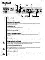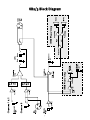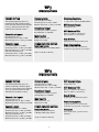
1
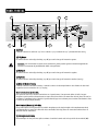
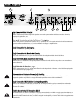
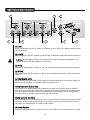
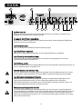
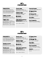
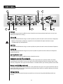
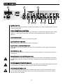
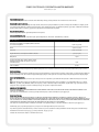
KB2/KB3
Keyboard Amplifier Owner Manual
For more information on other great Peavey products, go to your local Peavey dealer or online at www.peavey.com.
Intended to alert the user to the presence of uninsulated “dangerous voltage” within the product’s
enclosure that may be of sufficient magnitude to constitute a risk of electric shock to persons.
Intended to alert the user of the presence of important operating and maintenance (servicing)
instructions in the literature accompanying the product.
CAUTION: Risk of electrical shock — DO NOT OPEN!
CAUTION: To reduce the risk of electric shock, do not remove cover. No user serviceable parts inside.
Refer servicing to qualified service personnel.
WARNING: To prevent electrical shock or fire hazard, do not expose this appliance to rain or moisture.
Before using this appliance, read the operating guide for further warnings.
Este símbolo tiene el propósito, de alertar al usuario de la presencia de “(voltaje) peligroso” sin
aislamiento dentro de la caja del producto y que puede tener una magnitud suficiente como para
constituir riesgo de descarga eléctrica.
Este símbolo tiene el propósito de alertar al usario de la presencia de instruccones importantes sobre la
operación y mantenimiento en la información que viene con el producto.
PRECAUCION: Riesgo de descarga eléctrica ¡NO ABRIR!
PRECAUCION: Para disminuír el riesgo de descarga eléctrica, no abra la cubierta. No hay piezas útiles
dentro. Deje todo mantenimiento en manos del personal técnico cualificado.
ADVERTENCIA: Para evitar descargas eléctricas o peligro de incendio, no deje expuesto a la lluvia o
humedad este aparato Antes de usar este aparato, Iea más advertencias en la guía de operación.
Ce symbole est utilisé dans ce manuel pour indiquer à l’utilisateur la présence d’une tension dangereuse
pouvant être d’amplitude suffisante pour constituer un risque de choc électrique.
Ce symbole est utilisé dans ce manuel pour indiquer à l’utilisateur qu’il ou qu’elle trouvera d’importantes
instructions concernant l’utilisation et l’entretien de l’appareil dans le paragraphe signalé.
ATTENTION: Risques de choc électrique — NE PAS OUVRIR!
ATTENTION: Afin de réduire le risque de choc électrique, ne pas enlever le couvercle. Il ne se trouve à
l’intérieur aucune pièce pouvant être reparée par l’utilisateur. Confiez I’entretien et la réparation de
l’appareil à un réparateur Peavey agréé.
AVERTISSEMENT: Afin de prévenir les risques de décharge électrique ou de feu, n’exposez pas cet
appareil à la pluie ou à l’humidité. Avant d’utiliser cet appareil, lisez attentivement les avertissements
supplémentaires de ce manuel.
Dieses Symbol soll den Anwender vor unisolierten gefährlichen Spannungen innerhalb des Gehäuses
warnen, die von Ausreichender Stärke sind, um einen elektrischen Schlag verursachen zu können.
Dieses Symbol soll den Benutzer auf wichtige Instruktionen in der Bedienungsanleitung aufmerksam
machen, die Handhabung und Wartung des Produkts betreffen.
VORSICHT: Risiko — Elektrischer Schlag! Nicht öffnen!
VORSICHT: Um das Risiko eines elektrischen Schlages zu vermeiden, nicht die Abdeckung enfernen. Es
befinden sich keine Teile darin, die vom Anwender repariert werden könnten. Reparaturen nur von
qualifiziertem Fachpersonal durchführen lassen.
ACHTUNG: Um einen elektrischen Schlag oder Feuergefahr zu vermeiden, sollte dieses Gerät nicht dem
Regen oder Feuchtigkeit ausgesetzt werden. Vor Inbetriebnahme unbedingt die Bedienungsanleitung lesen.
2
IMPORTANT SAFETY INSTRUCTIONS
WARNING: When using electrical products, basic cautions should always be followed, including the following:
1.
2.
3.
4.
5.
6.
7.
8.
9.
10.
11.
12.
13.
14.
15.
16.
17.
18.
Read these instructions.
Keep these instructions.
Heed all warnings.
Follow all instructions.
Do not use this apparatus near water.
Clean only with a dry cloth.
Do not block any of the ventilation openings. Install in accordance with manufacturer’s instructions.
Do not install near any heat sources such as radiators, heat registers, stoves or other apparatus (including
amplifiers) that produce heat.
Do not defeat the safety purpose of the polarized or grounding-type plug. A polarized plug has two blades with one
wider than the other. A grounding type plug has two blades and a third grounding plug. The wide blade or third
prong is provided for your safety. If the provided plug does not fit into your outlet, consult an electrician for
replacement of the obsolete outlet.
Protect the power cord from being walked on or pinched, particularly at plugs, convenience receptacles, and the
point they exit from the apparatus.
Note for UK only: If the colors of the wires in the mains lead of this unit do not correspond with the terminals in your
plug‚ proceed as follows:
a) The wire that is colored green and yellow must be connected to the terminal that is marked by the letter E‚ the
earth symbol‚ colored green or colored green and yellow.
b) The wire that is colored blue must be connected to the terminal that is marked with the letter N or the color black.
c) The wire that is colored brown must be connected to the terminal that is marked with the letter L or the color red.
Only use attachments/accessories provided by the manufacturer.
Use only with a cart, stand, tripod, bracket, or table specified by the manufacturer, or sold with the apparatus. When
a cart is used, use caution when moving the cart/apparatus combination to avoid injury from tip-over.
Unplug this apparatus during lightning storms or when unused for long periods of time.
Refer all servicing to qualified service personnel. Servicing is required when the apparatus has been damaged in
any way, such as power-supply cord or plug is damaged, liquid has been spilled or objects have fallen into the
apparatus, the apparatus has been exposed to rain or moisture, does not operate normally, or has been dropped.
Never break off the ground pin. Write for our free booklet “Shock Hazard and Grounding.” Connect only to a power
supply of the type marked on the unit adjacent to the power supply cord.
If this product is to be mounted in an equipment rack, rear support should be provided.
Exposure to extremely high noise levels may cause a permanent hearing loss. Individuals vary considerably in
susceptibility to noise-induced hearing loss, but nearly everyone will lose some hearing if exposed to sufficiently
intense noise for a sufficient time. The U.S. Government’s Occupational and Health Administration (OSHA) has
specified the following permissible noise level exposures:
Duration Per Day In Hours
8
6
4
3
2
1 1⁄2
1
1
⁄2
1
⁄4 or less
Sound Level dBA, Slow Response
90
92
95
97
100
102
105
110
115
According to OSHA, any exposure in excess of the above permissible limits could result in some hearing loss. Ear plugs or protectors to the
ear canals or over the ears must be worn when operating this amplification system in order to prevent a permanent hearing loss, if exposure
is in excess of the limits as set forth above. To ensure against potentially dangerous exposure to high sound pressure levels, it is
recommended that all persons exposed to equipment capable of producing high sound pressure levels such as this amplification system be
protected by hearing protectors while this unit is in operation.
SAVE THESE INSTRUCTIONS!
3
ENGLISH
KB ®2/KB3
Keyboard Amplifiers
Thank you for selecting the KB2/KB3 keyboard amplifier. Once again‚ Peavey engineers have listened to input from
keyboard players and put together an amplifier that combines excellent features and sound in one portable package. The
KB Series amplifiers deliver awesome sound reproduction for all of your keyboard sounds—from thundering bass to
crystal highs—it’s all there!
Before you begin to play through your amp, it is very important to ensure the product has the proper AC line voltage
supplied. You can find the proper voltage for your amp printed next to the IEC line (power) cord on the rear panel of the
unit. For the KB3, an external speaker jack is provided for the additional use of an external speaker enclosure. This
feature is located on the rear panel as well and is also explained in this section. Each product feature is numbered. Refer
to the control and rear panel diagrams in this manual to locate the particular features next to their number.
Please read this guide carefully to ensure your personal safety as well as the safety of your amplifier.
Features
· 4-channels (KB2 and KB3)
· KB2: biamped 45 watts and 12 watts
· KB3: 80 watts external‚ 60 watts internal
· balanced line out
· effects send/return jack
· external speaker capability (KB3 only)
QUICK SET-UP GUIDE
1. Connect the line cord to the appropriately rated receptacle
2. Be certain that all levels are down or set to the fully counter-clockwise position and set
all the EQs flat
3. Set the master level to the 12:00 position
4. Connect left output of your keyboard to the left input of the KB2/KB3 and connect right
output of your keyboard to the right input of the KB2/KB3
5. Set the DDT switch to the enable position
6. Set the main/monitor switch to the monitor position
7. Turn on power to the KB2/KB3
8. Adjust the channel level for proper volume
9. Adjust the channel EQ as needed
4
FRONT PANEL
1
5
2
3
4
6
7
8
(1) Level
Controls the 1/4" jack input level on channels 1 and 2 and the 1/4" jack input and XLR input on channel 3.
(2) Low EQ
An active tone control (shelving type: +/-15 dB) that varies the low frequency range.
C a u t i o n : Excessive low frequency boost causes greater power consumption and increases the
possibility of speaker damage.
(3) Hi EQ
An active tone control (shelving type: ± 15 dB) that varies the hi frequency range.
(4) Mid EQ
An active tone control (peak/notch type: ± 15dB) that varies the mid frequencies. (channel 3)
(5) CH4/Monitor Level
Controls the input level for channel 4. Controls high-impedance microphones or other high-level sources
equipped with a 1/4" phone plug.
(6) Headphone Level (KB3 only)
This sets the level to the headphone jack on the rear panel. To avoid damage to your hearing‚ make sure
to turn the dial fully counter-clockwise before using headphones. Slowly turn the knob clockwise until a
comfortable listening level is set. This does not affect the master level.
(7) Master Level (KB3 only)
This knob sets the overall level for the unit. Make sure the Master level is completely down (full counterclockwise) before powering up the unit. This does not affect the headphone level.
(8) Power Switch
This two-way rocker switch applies power to the unit when placed in the ON position.
5
REAR PANEL
17
16
12
9
10
11
14
13
15
Main Line Out (9)
This low-noise‚ electronically-balanced XLR connector can be used to route signals to a mixing
console‚ recording device‚ etc.
Send/Return Jacks Mains (10 & 11)
This pair of 1/4" jacks allow the use of various auxiliary units (effects units‚ equalizers‚ etc.) in-line‚
before the power amp section.
Headphone Jack (12)
This 1/4" jack accepts stereo headphones only.
CH4/Monitor Input Jack (13)
Use this 1/4" jack to connect to the output of any line-level device.
Channel: 3 Low-Impedance Input (14)
For use with low-impedance microphones or other line-level sources equipped with a male XLR
connector.
Channels 3‚ 2 & 1 (15)
These 1/4" jacks accept high-impedance microphones or line-level sources equipped with 1⁄4" phone plugs.
External Speaker Jack (16) (KB3 only)
This 1/4" jack provides the powered signal from the amplifier. Use this jack to add a second speaker
cabinet in parallel. The external minimum speaker load impedance is 8 ohms.
IEC connector/detachable line cord (17)
This is a standard IEC power connector. An AC mains cord having the appropriate AC plug and ratings
for the intended operating voltage is included in the carton. The mains cord should be connected to
the amplifier before connecting to a suitable AC outlet.
U.S. Domestic AC Mains Cord
The mains cord supplied with the unit is heavy-duty‚ 3-conductor type with a conventional 120 VAC
plug with ground pin. Never break off the ground pin on any equipment. It is provided for your safety.
If the outlet used does not have a ground pin‚ a suitable grounding adapter should be used and the
third wire should be properly grounded.
6
KB2/3 Block Diagram
7
KB®3
SPECIFICATIONS
PREAMP SECTION
Channel 4 Input:
Frequency Response:
The following preamp specs are
measured @ 1 kHz‚ nominal signal
levels are with channel level controls
set at 5‚ minimum levels are with
channel level controls set at 10.
Input Impedance: 10k Ohms
Nominal Input Level: 0 dBV‚ 1 V RMS
Minimum Input Level: -25 dBV‚ 56 mV RMS
+0, -1 dB, 20Hz–20 kHz @ 30 W RMS/8 Ohms
Channel 1 & 2 Inputs:
Input Impedance: 100k
Nominal Input Level: 6 dBV‚ 2 V RMS
Minimum Input Level: -10 dBV‚ 316 mV RMS
Headphone Output
Load Impedance: 8 Ohms or greater
Nominal Output: 100 mW RMS
Main Line Out
Output Impedance: <100
Output Level: 18 dBV
Channel 3 Input:
POWER AMPLIFIER SECTION
Low Z Input Impedance: 10k Ohms
Nominal Input Level: -15 dBV‚ 178 mV RMS
Minimum Input Level: -33 dBV‚ 22 mV RMS
High Z Input Impedance: 75k
Nominal Input Level: -15 dBV‚ 178 mV RMS
Minimum Input Level: -33 dBV‚ 22 mV RMS
Rated Power & Load:
80 W RMS/4 Ohms or 60 W RMS/8 Ohms
DDT Dynamic Range:
Greater than 20 dB
DDT Maximum THD:
Below 0.5% THD for 6 dB overload
Below 1% THD for 20 dB overload
Hum & Noise:
Greater than 100 dB below rated power
Power Consumption:
120 W @ 120V AC‚ 50/60 Hz‚ Domestic
120 W @ 220–230/240V AC‚ 60 Hz‚ Export
(1 kHz, 1% THD @ 120 VAC line)
KB®2
SPECIFICATIONS
PREAMP SECTION
Channel 4 Input:
DDT Dynamic Range:
The following preamp specs are
measured @ 1 kHz‚ nominal signal
levels are with channel level controls
set at 5‚ minimum levels are with
channel level controls set at 10.
Input Impedance: 10 k Ohms
Nominal Input Level: 0 dBV‚ 1 V RMS
Minimum Input Level: -25 dBV‚ 56 mV RMS
Greater than 20 dB
Channel 1 & 2 Inputs:
Headphone Output
Below 0.5% THD for 6 dB overload
Below 1% THD for 20 dB overload
Load Impedance: 8 Ohms or greater
Nominal Output: 100 mW RMS
Hum & Noise:
Greater than 90 dB below rated power
Main Line Out
Input Impedance: 100 k
Nominal Input Level: 1.5 dBV‚ 1.2 V RMS
Minimum Input Level: -16 dBV‚ 158 mV RMS
Output Impedance: <100
Output Level: 18 dBV
Channel 3 Input:
POWER AMPLIFIER SECTION
Low Z Input Impedance: 10 k Ohms
Nominal Input Level: -21 dBV‚ 89 mV RMS
Minimum Input Level: -38 dBV‚ 13 mV RMS
High Z Input Impedance: 75 k
Nominal Input Level: -21 dBV‚ 89 mV RMS
Minimum Input Level: -38 dBV‚ 13 mV RMS
DDT Maximum THD:
Rated Power & Load:
45 W RMS/8 Ohms/low channel
12 W RMS/8 Ohms/high channel
(1 kHz, 1% THD @ 120 VAC line)
8
Power Consumption:
150 W @ 120V AC‚ 50/60 Hz‚ Domestic
150 W @ 220–230/240V AC‚ 60 Hz‚ Export
Crossover:
Fixed‚ 18 dB/octave‚ 3.5 kHz crossover
frequency
ESPAÑOL
KB ®2/KB3
Amplificadores para Teclados
Gracias por elegir los amplificadores para teclados KB2/KB3. Una vez más, los ingenieros de Peavey han escuchado las
peticiones de los tecladistas y las han integrado en un amplificador que combina excelentes funciones y sonido en una
unidad portable. La serie de amplificadores KB brinda reproducción de sonido inigualable para todos los sonidos de
teclados; de graves profundos a agudos cristalinos, todo está ahí.
Antes de comenzar a tocar con el amplificador, es muy importante asegurarse que el producto cuenta con la corriente
apropiada. Puedes encontrar la corriente apropiada de tu amplificador, impresa junto a la conexión de corriente IEC en el
panel trasero de la unidad. El KB3 incluye un conectador para un parlante externo se incluye para un gabinete adicional.
Esta función se localiza en la parte trasera de la unidad y es explicada en esta sección. Cada función del producto está
enumerada. Haz referencia a los diagramas de los paneles delantero y trasero en este manual para localizar las
funciones al lado de su número.
Por favor lee esta guía cuidadosamente para asegurar tu seguridad personal, así como la seguridad de tu amplificador.
Caracteristicas
· 4-channels (KB2 and KB3)
· KB2: biamped 45 watts and 12 watts
· KB3: 80 watts external‚ 60 watts internal
· balanced line out
· effects send/return jack
· external speaker capability (KB3 only)
GUÍA DE INSTALACIÓN RÁPIDA
1. Conecta el cable de corriente a una fuente apropiada
2. Asegúrate que los niveles están abajo o ajustados completamente en dirección contraria a las
manecillas del reloj y que el ecualizador (EQ) está plano.
3. Ajusta el nivel maestro a la posición 12:00.
4. Conecta la salida izquierda del teclado a la entrada izquierda del KB2/KB3 y conecta la salida derecha
del teclado a la entrada derecha del KB2/KB3.
5. Ajusta el interruptor de DDT a la posición de activo.
6. Ajusta el interruptor main/monitor a la posición de monitor.
7. Enciende el KB2/KB3.
8. Ajusta el nivel del canal al volumen apropiado.
9. Ajusta el EQ como sea necesario.
9
PANEL FRONTAL
1
5
2
3
4
6
7
8
(1) Nivel
Controla el nivel de la salida de 1/4" en los canales 1 y 2 y la entrada de 1/4" y entrada XLR del canal 3.
(2) EQ Grave
Un control de tono activo (tipo shelving: ±15 dB) que varía el rango de frecuencias graves.
C u i d a d o : Los incrementos excesivos en las frecuencias graves pueden generar consumo exagerado de
corriente e incrementar la posibilidad de daños a los parlantes.
(3) EQ Agudo
Un control de tono activo (tipo shelving: ±15 dB) que varía el rango de frecuencias agudas.
(4) EQ Medio
Un control de tono activo (tipo shelving: ±15 dB) que varía el rango de frecuencias medias (canal 3).
(5) Nivel del Monitor/Canal 4
Controla el nivel de entrada del canal 4. Controla los micros de alta impedancia u otras fuentes de alto nivel
equipadas con un conectador de 1/4" de plug.
Nivel de Auriculares (6) Sólo KB3
Este ajusta el nivel de la salida de auriculares en el panel trasero. Para prevenir daños del oído, hay que
asegurarse que la perilla está totalmente en contra de la dirección de las manecillas del reloj antes de usar los
auriculares. Lentamente sube el nivel de la perilla hasta llegar a un volumen para escuchar cómodamente. Esto
no afecta el nivel principal (master).
Nivel Principal (Master) (7) Sólo KB3
Esta perilla ajusta el nivel general de la unidad. Asegúrate que el nivel principal está completamente abajo
(completamente en contra de la dirección de las manecillas del reloj) antes de encender la unidad. Esto no
afecta el nivel de auriculares.
(8) Interruptor de Corriente
Este interruptor de dos pociones aplica corriente a la unidad cuando está en la posición de encendido (ON).
10
PANEL TRASERO
17
16
9
12
10
11
13
14
15
(9) Línea de Salida Principal
Estos conectadores XLR de bajo ruido pueden ser usados para mandar señales a consolas de mezcla,
equipo de grabación, etc.
(10 y 11) Conectadores de Envío/Retorno Principales
Estos dos pares de conectadores estéreo de 1/4" permiten el uso de varias unidades de efectos externas
(procesadores, ecualizadores, etc.) en la señal antes de llegar al amplificador.
(12) Conectador de Auriculares
Este conectador de 14/" acepta auriculares estéreo solamente.
(13) Conectador de Monitor del Canal 4
Usa este conectador de 1/4" para conectar la salida de cualquier unidad de nivel de línea.
(14) Entrada de Baja Impedancia del Canal 3
Para usarse con micrófonos de baja impedancia o fuentes de nivel de línea equipados con conectadores
masculinos XLR.
(15) Entradas de Canales 3, 2 y 1
Estos conectadores de 1/4" aceptan micrófonos de alta impedancia o fuentes de nivel de línea equipadas
con conectadores tipo plug de 1/4".
Conectador de Parlante Externo (16) Sólo KB3
Este conectador de 1/4" provee señal amplificada del amplificador. Usa esta conexión para añadir un
segundo parlante en paralelo. La carga mínima del parlante externo debe ser 8 ohmios.
(17) Conectador IEC/Cable de Corriente Removible
Este es un conectador estándar de corriente IEC. Se incluye un cable con las características adecuadas
para la operación de esta unidad. El cable debe ser conectado al amplificador antes de conectarse a la
fuente de corriente.
Cable de corriente CA Domestico EE.UU.
El cable incluido es de tres conductores con plug convencional de 120 VAC con aguja para tierra. Nunca se
arranque la aguja de tierra de ningún equipo. Esta ha sido incluida para tu seguridad. Si la conexión de la
pared no incluye entrada de tierra, se debe conseguir un adaptador y el tercer cable debe ser propiamente
aterrizado.
11
KB®3
SPEZIFIKATIONEN
PREAMP SECTION
Channel 4 Input:
Frequency Response:
The following preamp specs are
measured @ 1 kHz‚ nominal signal
levels are with channel level controls
set at 5‚ minimum levels are with
channel level controls set at 10.
Input Impedance: 10 k Ohms
Nominal Input Level: 0 dBV‚ 1 V RMS
Minimum Input Level: -25 dBV‚ 56 mV RMS
+0, -1 dB, 20Hz–20 kHz @ 30 W RMS/8 Ohms
Channel 1 & 2 Inputs:
Input Impedance: 100 k
Nominal Input Level: 6 dBV‚ 2 V RMS
Minimum Input Level: -10 dBV‚ 316 mV RMS
Headphone Output
Load Impedance: 8 Ohms or greater
Nominal Output: 100 mW RMS
Main Line Out
Output Impedance: <100
Output Level: 18 dBV
Channel 3 Input:
POWER AMPLIFIER SECTION
Low Z Input Impedance: 10 k Ohms
Nominal Input Level: -15 dBV‚ 178 mV RMS
Minimum Input Level: -33 dBV‚ 22 mV RMS
High Z Input Impedance: 75 k
Nominal Input Level: -15 dBV‚ 178 mV RMS
Minimum Input Level: -33 dBV‚ 22 mV RMS
Rated Power & Load:
80 W RMS/4 Ohms or 60 W RMS/8 Ohms
DDT Dynamic Range:
Greater than 20 dB
DDT Maximum THD:
Below 0.5% THD for 6 dB overload
Below 1% THD for 20 dB overload
Hum & Noise:
Greater than 100 dB below rated power
Power Consumption:
120 W @ 120V AC‚ 50/60 Hz‚ Domestic
120 W @ 220–230/240V AC‚ 60 Hz‚ Export
(1 kHz, 1% THD @ 120 VAC line)
KB®2
SPEZIFIKATIONEN
PREAMP SECTION
Channel 4 Input:
DDT Dynamic Range:
The following preamp specs are
measured @ 1 kHz‚ nominal signal
levels are with channel level controls
set at 5‚ minimum levels are with
channel level controls set at 10.
Input Impedance: 10 k Ohms
Nominal Input Level: 0 dBV‚ 1 V RMS
Minimum Input Level: -25 dBV‚ 56 mV RMS
Greater than 20 dB
Channel 1 & 2 Inputs:
Headphone Output
Below 0.5% THD for 6 dB overload
Below 1% THD for 20 dB overload
Load Impedance: 8 Ohms or greater
Nominal Output: 100 mW RMS
Hum & Noise:
Greater than 90 dB below rated power
Main Line Out
Input Impedance: 100 k
Nominal Input Level: 1.5 dBV‚ 1.2 V RMS
Minimum Input Level: -16 dBV‚ 158 mV RMS
Output Impedance: <100
Output Level: 18 dBV
Channel 3 Input:
POWER AMPLIFIER SECTION
Low Z Input Impedance: 10 k Ohms
Nominal Input Level: -21 dBV‚ 89 mV RMS
Minimum Input Level: -38 dBV‚ 13 mV RMS
High Z Input Impedance: 75 k
Nominal Input Level: -21 dBV‚ 89 mV RMS
Minimum Input Level: -38 dBV‚ 13 mV RMS
DDT Maximum THD:
Rated Power & Load:
45 W RMS/8 Ohms/low channel
12 W RMS/8 Ohms/high channel
(1 kHz, 1% THD @ 120 VAC line)
12
Power Consumption:
150 W @ 120V AC‚ 50/60 Hz‚ Domestic
150 W @ 220–230/240V AC‚ 60 Hz‚ Export
Crossover:
Fixed‚ 18 dB/octave‚ 3.5 kHz crossover
frequency
DEUTSCH
KB®2/KB3
Keyboard-Verstärker
Wir möchten uns bei Ihnen dafür bedanken, dass Sie sich für den Keyboard-Verstärker KB2/KB3 entschieden haben. Auch hier
haben sich die Techniker von Peavey die Meinungen von Keyboardern zu Herzen genommen und einen Verstärker entwickelt,
der herausragende Funktionen und ausgezeichneten Klang in einem einzigen tragbaren Gerät kombiniert. Die Verstärker der
KB-Serie liefern eine beeindruckende Klangwiedergabe all Ihrer Keyboard-Sounds – von donnernden Bässen bis hin zu
kristallklaren Höhen steckt alles drin!
Bevor Sie beginnen, über Ihren Verstärker zu spielen, müssen Sie sicherstellen, dass das Gerät an die korrekte
Wechselspannung angeschlossen ist. Die für Ihr Gerät korrekte Spannung ist neben dem IEC-Netzkabel auf der Rückseite des
Geräts aufgedruckt. Der KB3 verfügt zudem über eine externe Lautsprecherklinke für den Einsatz einer zusätzlichen externen
Lautsprecherbox. Diese befindet sich ebenfalls auf der Rückseite und wird in diesem Abschnitt erläutert. Jede Funktion des
Produkts ist nummeriert. Die jeweiligen Funktionen finden Sie mit der entsprechenden Nummer auf den Abbildungen der
Regler bzw. Rückseite des Geräts in dieser Anleitung.
Lesen Sie sich diese Anleitung bitte sorgfältig durch, damit sowohl Ihre Sicherheit als auch die Ihres Geräts gewährleistet ist.
Merkmale
· Vier Kanäle (KB2 und KB3)
· KB2: Bi-Amping (45 Watt und 12 Watt)
· KB3: 80 Watt extern, 60 Watt intern
· Symmetrierter Line-Ausgang
· Effects-Send/Return-Klinke
· Anschlussmöglichkeit für externen Lautsprecher (nur KB3)
SETUP-KURZANLEITUNG
1.Schließen Sie das Netzkabel an eine Steckdose mit den korrekten Werten an.
2.Achten Sie darauf, dass sämtliche Pegel herunter oder vollständig im entgegengesetzten
Uhrzeigersinn gedreht sind, und stellen Sie alle EQs neutral ein.
3.Stellen Sie den Master-Pegel auf die Position 12:00.
4.Schließen Sie den linken Ausgang Ihres Keyboards an den linken Eingang des KB2/KB3 und
den rechten Ausgang Ihres Keyboards an den rechten Eingang des KB2/KB3 an.
5.Aktivieren Sie den DDT-Schalter.
6.Stellen Sie den Main/Monitor-Schalter auf die Position Monitor.
7.Schalten Sie die Stromversorgung des KB2/KB3 ein.
8.Stellen Sie den Kanalpegel auf die angemessene Lautstärke ein.
9. Stellen Sie den Kanal-EQ nach Bedarf ein.
13
FUNKTIONEN AN DER VORDERSEITE
1
5
2
3
4
6
7
8
(1) Level
Regelt den Eingangspegel der 1/4"-Klinke an den Kanälen 1 und 2 und den 1/4"-Klinkeneingang und XLREingang an Kanal 3.
(2) Low EQ
Aktiver Klangregler (stufenlos regelbar, ±15 dB), mit dem der Niederfrequenzbereich variiert werden kann.
A c h t u n g : Ein übermäßiges Anheben der Niederfrequenzen führt zu erhöhtem Stromverbrauch und
steigert das Risiko einer Beschädigung der Lautsprecher.
(3) Hi EQ
Aktiver Klangregler (stufenlos regelbar, ±15 dB), mit dem der Hochfrequenzbereich variiert werden kann.
(4) Mid EQ
Aktiver Klangregler (Typ Spitze/Kerbe, ±15 dB), mit dem der Mittenfrequenzbereich variiert werden kann.
(Kanal 3)
(5) CH4/Monitor Level
Regelt den Eingangspegel für Kanal 4. Zur Regelung hochohmiger Mikrophone oder anderer Quellen mit
hohem Pegel, die mit einem 1/4"-Kopfhörerstecker ausgestattet sind.
Headphone Level (6) (nur KB3)
Hiermit wird der zur Kopfhörerklinke auf der Rückseite gesendete Pegel geregelt. Um Hörschäden zu
vermeiden, muss dieser Regler vollständig im entgegengesetzten Uhrzeigersinn heruntergedreht werden,
bevor Sie Kopfhörer verwenden. Drehen Sie den Knopf langsam im Uhrzeigersinn, bis ein angenehmer
Hörpegel erreicht ist. Der Master-Pegel wird dadurch nicht verändert.
Master Level (7) (nur KB3)
Mit diesem Regler wird der Gesamtpegel des Geräts eingestellt. Achten Sie darauf, dass der Master-Pegel
vollständig heruntergedreht ist (vollständig im entgegengesetzten Uhrzeigersinn), bevor Sie das Gerät
einschalten. Der Kopfhörerpegel wird dadurch nicht verändert.
(8) Power-Schalter
Steht dieser Kippschalter mit zwei Positionen auf der Position ON, wird das Gerät mit Netzstrom versorgt.
14
REAR PANEL
17
16
9
12
10
11
13
14
15
(9) Main Line Out
Dieser geräuscharme, elektronisch symmetrierte XLR-Stecker kann zum Senden von Signalen an ein
Mischpult, ein Tonbandgerät usw. eingesetzt werden.
(10 und 11) Send/Return Jacks Mains
Dieses Paar 1/4"-Klinken ermöglicht das Einschleifen verschiedener Zusatzvorrichtungen (Effektgeräte,
Equalizer usw.) vor der Verstärkerstufe.
(12) Headphone Jack
Diese 1/4"-Klinke ist ausschließlich für Stereokopfhörer geeignet.
(13) CH4/Monitor Input Jack
Mit dieser 1/4"-Klinke erfolgt der Anschluss an den Ausgang beliebiger Line-Pegelgeräte.
(14) Channel 3 Low-Impedance Input
Für den Einsatz mit niederohmigen Mikrophonen oder anderen Line-Pegelquellen, die mit einem
männlichen XLR-Stecker ausgestattet sind.
(15) Kanäle 3‚ 2 und 1
An diese 1/4"-Klinken können hochohmige Mikrophone oder Line-Pegelquellen angeschlossen werden, die
mit 1/4"-Kopfhörersteckern ausgestattet sind.
External Speaker Jack (16) (nur KB3)
Diese 1/4"-Klinke liefert das verstärkte Signal vom Verstärker. Über diese Klinke können Sie eine zweite
Lautsprecherbox parallel anschließen. Die externe Mindest-Lautsprecherlastimpedanz beträgt 8 Ohm.
(17) IEC-Stecker/abziehbares Netzkabel
Hierbei handelt es sich um einen genormten IEC-Netzstecker. Ein Wechselstrom-Netzkabel mit dem
entsprechenden Wechselstromstecker und den entsprechenden Werten für die erforderliche
Betriebsspannung liegt bei. Das Netzkabel muss an den Verstärker angeschlossen werden, bevor es an
eine geeignete Wechselstromsteckdose angeschlossen wird.
Wechselstrom-Netzkabel für die USA
Bei diesem dem Gerät beiliegenden Netzkabel handelt es sich um ein robustes, dreiadriges Kabel mit
einem herkömmlichen 120-V-Wechselstromstecker mit Erdungsstift. Der Erdungsstift darf in keinem Fall an
irgendeinem Gerät entfernt werden. Er ist zu Ihrer Sicherheit vorhanden. Ist die verwendete Steckdose
nicht mit einem Erdungsstift ausgestattet, muss ein geeigneter Erdungsadapter verwendet und die dritte
Ader korrekt geerdet werden.
15
KB®3
SPEZIFIKATIONEN
PREAMP SECTION
Channel 4 Input:
Frequency Response:
The following preamp specs are
measured @ 1 kHz‚ nominal signal
levels are with channel level controls
set at 5‚ minimum levels are with
channel level controls set at 10.
Input Impedance: 10 k Ohms
Nominal Input Level: 0 dBV‚ 1 V RMS
Minimum Input Level: -25 dBV‚ 56 mV RMS
+0, -1 dB, 20Hz–20 kHz @ 30 W RMS/8 Ohms
Channel 1 & 2 Inputs:
Headphone Output
Load Impedance: 8 Ohms or greater
Nominal Output: 100 mW RMS
Main Line Out
Input Impedance: 100 k
Nominal Input Level: 6 dBV‚ 2 V RMS
Minimum Input Level: -10 dBV‚ 316 mV RMS
Output Impedance: <100
Output Level: 18 dBV
Channel 3 Input:
POWER AMPLIFIER SECTION
Low Z Input Impedance: 10 k Ohms
Nominal Input Level: -15 dBV‚ 178 mV RMS
Minimum Input Level: -33 dBV‚ 22 mV RMS
High Z Input Impedance: 75 k
Nominal Input Level: -15 dBV‚ 178 mV RMS
Minimum Input Level: -33 dBV‚ 22 mV RMS
Rated Power & Load:
80 W RMS/4 Ohms or 60 W RMS/8 Ohms
DDT Dynamic Range:
Greater than 20 dB
DDT Maximum THD:
Below 0.5% THD for 6 dB overload
Below 1% THD for 20 dB overload
Hum & Noise:
Greater than 100 dB below rated power
Power Consumption:
120 W @ 120V AC‚ 50/60 Hz‚ Domestic
120 W @ 220–230/240V AC‚ 60 Hz‚ Export
(1 kHz, 1% THD @ 120 VAC line)
KB®2
SPEZIFIKATIONEN
PREAMP SECTION
Channel 4 Input:
DDT Dynamic Range:
The following preamp specs are
measured @ 1 kHz‚ nominal signal
levels are with channel level controls
set at 5‚ minimum levels are with
channel level controls set at 10.
Input Impedance: 10 k Ohms
Nominal Input Level: 0 dBV‚ 1 V RMS
Minimum Input Level: -25 dBV‚ 56 mV RMS
Greater than 20 dB
Channel 1 & 2 Inputs:
Headphone Output
Load Impedance: 8 Ohms or greater
Nominal Output: 100 mW RMS
Hum & Noise:
Greater than 90 dB below rated power
Main Line Out
Input Impedance: 100 k
Nominal Input Level: 1.5 dBV‚ 1.2 V RMS
Minimum Input Level: -16 dBV‚ 158 mV RMS
Output Impedance: <100
Output Level: 18 dBV
Channel 3 Input:
POWER AMPLIFIER SECTION
Low Z Input Impedance: 10 k Ohms
Nominal Input Level: -21 dBV‚ 89 mV RMS
Minimum Input Level: -38 dBV‚ 13 mV RMS
High Z Input Impedance: 75 k
Nominal Input Level: -21 dBV‚ 89 mV RMS
Minimum Input Level: -38 dBV‚ 13 mV RMS
DDT Maximum THD:
Below 0.5% THD for 6 dB overload
Below 1% THD for 20 dB overload
Rated Power & Load:
45 W RMS/8 Ohms/low channel
12 W RMS/8 Ohms/high channel
(1 kHz, 1% THD @ 120 VAC line)
16
Power Consumption:
150 W @ 120V AC‚ 50/60 Hz‚ Domestic
150 W @ 220–230/240V AC‚ 60 Hz‚ Export
Crossover:
Fixed‚ 18 dB/octave‚ 3.5 kHz crossover
frequency
FRANÇAIS
KB®2/KB3
Amplificateurs pour Claviers
Merci d’avoir choisi un amplificateur KB2 ou KB3 de Peavey. Une fois de plus, notre équipe d’ingénieur s’est surpassée pour
rassembler dans une unité compacte toutes les fonctionnalités et qualités de diffusion qui font de votre amplificateur un outil
idéal pour de très nombreuses applications.
Avant de commencer à utiliser votre amplificateur, il est important de vérifier que votre unité est en accordance avec les
caractéristiques de votre alimentation électrique locale. Les besoins électriques de votre unité sont annotés proche du
connecteur d’alimentation IEC sur le panneau arrière. Le KB3 possède également à cet emplacement d’une sortie pour hautparleur externe. Cette connectique, ainsi que toutes les autres fonctions de votre unité sont détaillées plus loin dans ce
manuel. Chaque contrôle est numéroté, reportez-vous au diagramme correspondant à votre unité pour les localiser sur votre
amplificateur.
Il est important pour votre propre sécurité ainsi que celle de votre martériel de lire attentivement ce manuel.
Caractéristiques
· Unité de mixage 4-canaux (KB2 et KB3)
· KB2: système biamplifié de 45 + 12 watts
· KB3: 60 watts , 80 watts avec haut-parleur supplémentaire
· Sortie symétrisée de niveau ligne
· Boucle d’effets
· Sortie haut-parleur supplémentaire (KB3 seulement)
INSTALLATION RAPIDE
1. Connectez le cordon d’alimentation électrique à une source appropriée
2. Vérifiez que tous les niveaux de votre unité soient au minimum et les équalisations plates
3. Positionnez le niveau général sur “12 heures”
4. Connectez les sorties droites et gauches de votre clavier aux entrées respectives droites et
gauches de votre amplificateur KB
5. Positionnez l’interrupteur DDT sur la position active (Enable)
6. Positionnez que le sélecteur de mode Main/Monitor soit en position Main
7. Mettez votre unité sous tension
8. Ajustez le niveau d’entrée par canal pour le volume désiré
9. Ajustez l’équalisiation par canal selon besoin
17
FRONT PANEL
1
5
2
3
4
6
7
8
(1) Level
Ce contrôle vous permet de modifier le niveau d’entrée du canal correspondant (entrée Jack sur canal 1 & 2,
entrées Jack et XLR sur le canal 3).
(2) Low EQ
Ce contrôle actif (déformation de type escalier ±15 dB) vous permet de varier le niveau des basses fréquences.
Attention: Trop de basses fréquences engendre une consommation électrique anormale et risque
d’endommager le(s) haut-parleur(s).
(3) Hi EQ
Ce contrôle actif (déformation de type escalier ±15 dB) vous permet de varier le niveau des hautes fréquences.
(4) Mid EQ
Ce contrôle actif (déformation de type bosse/creux ±15 dB) vous permet de varier le niveau des fréquences
médium (channel 3).
(5) CH4/Monitor Level
Ce contrôle vous permet de modifier le niveau d’entrée du canal 4.
Headphone Level (6) (KB3 seulement)
Ce contrôle vous permet de varier le niveau de la sortie casque située sur le panneau arrière. Pour éviter
d’endommager votre audition, assurez-vous qu’il soit en position minimum avant de connecter votre casque
d’écoute, et augmenter alors jusqu’au niveau désiré. Ce contrôle n’affecte pas le niveau général de votre unité.
Master Level (7) (KB3 seulement)
Ce contrôle vous permet de varier le niveau de sortie général. Assurez qu’il soit en position minimum avant de
mettre votre unité sous tension et augmenter alors jusqu’au niveau désiré. Ce contrôle n’affecte pas le niveau
de la sortie du casque d’écoute.
(8)Power Switch
Cet interrupteur vous permet de mettre votre unité sous et hors tension (position ON indique unité sous
tension).
18
PANEL TRASERO
17
16
9
12
10
11
13
14
15
(9) Main Line Out
Cette sortie électroniquement balancée en XLR peut être utilisée pour envoyer le signal général à une unité
de mixage, enregistreur,...
(10 & 11) Send/Return Jacks Mains
Ces Jack 1/4" vous permettent de connecter une unité externe de traitement de signal (processeur d’effets,
égaliseurs,…) avant l’étage de puissance. Send est la sortie du préampli, Return l’entrée de l’étage de
puissance.
(12) Headphone Jack
Ce Jack vous permet de connecter un casque d’écoute stéréo.
(13) CH4/Monitor Input Jack
Utilisez ce connecteur pour amplifier un signal de niveau ligne.
(14) Channel: 3 Low-Impedance Input
Cette entrée vous permet de connecter une source de basse impédance ou tout signal de niveau ligne au
format XLR.
(15) Channels 3‚ 2 & 1
Ces entrées vous permettent de connecter une source de haute-impédance ou tout signal de niveau ligne
au format Jack.
External Speaker Jack (16) (KB3 seulement)
Ce connecteur est relié à la sortie de l’étage de puissance de votre unité. Pour l’utilisation d’une enceinte
supplémentaire, connectez son entrée à cette sortie. L’impédance de cette enceinte doit être supérieure à
8 ohms.
(17) IEC connector/detachable line cord
Ce connecteur standard IEC vous permet de connecter un cable standard d’alimentation électrique (fourni).
Ce cable doit être connecté à votre unité avant d’être relié à la source d’alimentation.
U.S. Domestic AC Mains Cord
Le cable d’alimentation électrique fourni est à utiliser avec une prise de terre conventionnelle. Assurezvous que votre unité soit correctement relié à la terre avant toute utilisation pour votre propre sécurité
ainsi que celle de votre matériel.
19
KB®3
ESPECIFICCIONES
PREAMP SECTION
Channel 4 Input:
Frequency Response:
The following preamp specs are
measured @ 1 kHz‚ nominal signal
levels are with channel level controls
set at 5‚ minimum levels are with
channel level controls set at 10.
Input Impedance: 10k Ohms
Nominal Input Level: 0 dBV‚ 1 V RMS
Minimum Input Level: -25 dBV‚ 56 mV RMS
+0, -1 dB, 20Hz–20 kHz @ 30 W RMS/8 Ohms
Channel 1 & 2 Inputs:
Headphone Output
Load Impedance: 8 Ohms or greater
Nominal Output: 100 mW RMS
Main Line Out
Input Impedance: 100k
Nominal Input Level: 6 dBV‚ 2 V RMS
Minimum Input Level: -10 dBV‚ 316 mV RMS
Output Impedance: <100
Output Level: 18 dBV
Channel 3 Input:
POWER AMPLIFIER SECTION
Low Z Input Impedance: 10k Ohms
Nominal Input Level: -15 dBV‚ 178 mV RMS
Minimum Input Level: -33 dBV‚ 22 mV RMS
High Z Input Impedance: 75k
Nominal Input Level: -15 dBV‚ 178 mV RMS
Minimum Input Level: -33 dBV‚ 22 mV RMS
Rated Power & Load:
80 W RMS/4 Ohms or 60 W RMS/8 Ohms
DDT Dynamic Range:
Greater than 20 dB
DDT Maximum THD:
Below 0.5% THD for 6 dB overload
Below 1% THD for 20 dB overload
Hum & Noise:
Greater than 100 dB below rated power
Power Consumption:
120 W @ 120V AC‚ 50/60 Hz‚ Domestic
120 W @ 220–230/240V AC‚ 60 Hz‚ Export
(1 kHz, 1% THD @ 120 VAC line)
KB®2
ESPECIFICCIONES
PREAMP SECTION
Channel 4 Input:
DDT Dynamic Range:
The following preamp specs are
measured @ 1 kHz‚ nominal signal
levels are with channel level controls
set at 5‚ minimum levels are with
channel level controls set at 10.
Input Impedance: 10 k Ohms
Nominal Input Level: 0 dBV‚ 1 V RMS
Minimum Input Level: -25 dBV‚ 56 mV RMS
Greater than 20 dB
Channel 1 & 2 Inputs:
Headphone Output
Load Impedance: 8 Ohms or greater
Nominal Output: 100 mW RMS
Hum & Noise:
Greater than 90 dB below rated power
Main Line Out
Input Impedance: 100 k
Nominal Input Level: 1.5 dBV‚ 1.2 V RMS
Minimum Input Level: -16 dBV‚ 158 mV RMS
Output Impedance: <100
Output Level: 18 dBV
Channel 3 Input:
POWER AMPLIFIER SECTION
Low Z Input Impedance: 10 k Ohms
Nominal Input Level: -21 dBV‚ 89 mV RMS
Minimum Input Level: -38 dBV‚ 13 mV RMS
High Z Input Impedance: 75 k
Nominal Input Level: -21 dBV‚ 89 mV RMS
Minimum Input Level: -38 dBV‚ 13 mV RMS
DDT Maximum THD:
Below 0.5% THD for 6 dB overload
Below 1% THD for 20 dB overload
Rated Power & Load:
45 W RMS/8 Ohms/low channel
12 W RMS/8 Ohms/high channel
(1 kHz, 1% THD @ 120 VAC line)
20
Power Consumption:
150 W @ 120V AC‚ 50/60 Hz‚ Domestic
150 W @ 220–230/240V AC‚ 60 Hz‚ Export
Crossover:
Fixed‚ 18 dB/octave‚ 3.5 kHz crossover
frequency
NOTES:
21
NOTES:
22
PEAVEY ELECTRONICS CORPORATION LIMITED WARRANTY
Effective Date: July 1, 1998
What This Warranty Covers
Your Peavey Warranty covers defects in material and workmanship in Peavey products purchased and serviced in the U.S.A. and Canada.
What This Warranty Does Not Cover
The Warranty does not cover: (1) damage caused by accident, misuse, abuse, improper installation or operation, rental, product modification or neglect; (2) damage occurring during shipment; (3) damage caused by repair or service performed by persons not authorized by Peavey; (4) products on which the serial number
has been altered, defaced or removed; (5) products not purchased from an Authorized Peavey Dealer.
Who This Warranty Protects
This Warranty protects only the original retail purchaser of the product.
How Long This Warranty Lasts
The Warranty begins on the date of purchase by the original retail purchaser. The duration of the Warranty is as follows:
Product Category
Duration
Guitars/Basses, Amplifiers, Pre-Amplifiers, Mixers, Electronic
Crossovers and Equalizers
2 years *(+ 3 years)
Drums
2 years *(+ 1 year)
Enclosures
3 years *(+ 2 years)
Digital Effect Devices and Keyboard and MIDI Controllers
1 year *(+ 1 year)
Microphones
2 years
Speaker Components (incl. speakers, baskets, drivers,
diaphragm replacement kits and passive crossovers)
and all Accessories
1 year
Tubes and Meters
90 days
[*Denotes additional warranty period applicable if optional Warranty Registration Card is completed and returned to Peavey by original retail purchaser within 90 days of purchase.]
What Peavey Will Do
We will repair or replace (at Peavey's discretion) products covered by warranty at no charge for labor or materials. If the product or component must be shipped to
Peavey for warranty service, the consumer must pay initial shipping charges. If the repairs are covered by warranty, Peavey will pay the return shipping charges.
How To Get Warranty Service
(1) Take the defective item and your sales receipt or other proof of date of purchase to your Authorized Peavey Dealer or Authorized Peavey Service Center.
OR
(2) Ship the defective item, prepaid, to Peavey Electronics Corporation, International Service Center, 412 Highway 11 & 80 East, Meridian, MS 39301 or Peavey
Canada Ltd., 95 Shields Court, Markham, Ontario, Canada L3R 9T5. Include a detailed description of the problem, together with a copy of your sales receipt or
other proof of date of purchase as evidence of warranty coverage. Also provide a complete return address.
Limitation of Implied Warranties
ANY IMPLIED WARRANTIES, INCLUDING WARRANTIES OF MERCHANTABILITY AND FITNESS FOR A PARTICULAR PURPOSE, ARE LIMITED IN DURATION TO THE
LENGTH OF THIS WARRANTY.
Some states do not allow limitations on how long an implied warranty lasts, so the above limitation may not apply to you.
Exclusions of Damages
PEAVEY'S LIABILITY FOR ANY DEFECTIVE PRODUCT IS LIMITED TO THE REPAIR OR REPLACEMENT OF THE PRODUCT, AT PEAVEY'S OPTION. IF WE ELECT TO
REPLACE THE PRODUCT, THE REPLACEMENT MAY BE A RECONDITIONED UNIT. PEAVEY SHALL NOT BE LIABLE FOR DAMAGES BASED ON INCONVENIENCE, LOSS OF
USE, LOST PROFITS, LOST SAVINGS, DAMAGE TO ANY OTHER EQUIPMENT OR OTHER ITEMS AT THE SITE OF USE, OR ANY OTHER DAMAGES WHETHER INCIDENTAL,
CONSEQUENTIAL OR OTHERWISE, EVEN IF PEAVEY HAS BEEN ADVISED OF THE POSSIBILITY OF SUCH DAMAGES.
Some states do not allow the exclusion or limitation of incidental or consequential damages, so the above limitation or exclusion may not apply to you.
This Warranty gives you specific legal rights, and you may also have other rights which vary from state to state.
If you have any questions about this warranty or service received or if you need assistance in locating an Authorized Service Center, please contact the Peavey
International Service Center at (601) 483-5365 / Peavey Canada Ltd. at (905) 475-2578.
Features and specifications subject to change without notice.
23
Features and specifications subject to change without notice.
Peavey Electronics Corporation • 711 A Street • Meridian • MS • 39301
(601) 483-5365 • FAX (601) 486-1278 • www.peavey.com
©2003
80305062
Printed in the U.S.A. 4/03