1
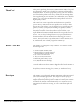
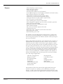
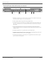
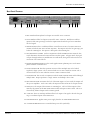
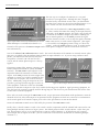
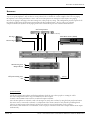
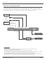
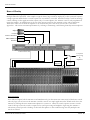
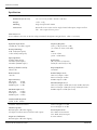
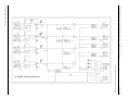
Automix 4
TM
Four Channel
Mini Automatic Mixer
User Manual
Intended to alert the user to the presence of uninsulated “dangerous voltage” within the product’s
enclosure that may be of sufficient magnitude to constitute a risk of electric shock to persons.
Intended to alert the user of the presence of important operating and maintenance (servicing)
instructions in the literature accompanying the product.
CAUTION: Risk of electrical shock — DO NOT OPEN!
CAUTION: To reduce the risk of electric shock, do not remove cover. No user serviceable parts inside. Refer
servicing to qualified service personnel.
WARNING: To prevent electrical shock or fire hazard, do not expose this appliance to rain or moisture. Before
using this appliance, read the operating guide for further warnings.
Este símbolo tiene el propósito, de alertar al usuario de la presencia de “(voltaje) peligroso” sin aislamiento dentro de la caja del producto y que puede tener una magnitud suficiente como para constituir
riesgo de descarga eléctrica.
Este símbolo tiene el propósito de alertar al usario de la presencia de instruccones importantes sobre la
operación y mantenimiento en la información que viene con el producto.
PRECAUCION: Riesgo de descarga eléctrica ¡NO ABRIR!
PRECAUCION: Para disminuír el riesgo de descarga eléctrica, no abra la cubierta. No hay piezas útiles dentro.
Deje todo mantenimiento en manos del personal técnico cualificado.
ADVERTENCIA: Para evitar descargas eléctricas o peligro de incendio, no deje expuesto a la lluvia o humedad
este aparato Antes de usar este aparato, Iea más advertencias en la guía de operación.
Ce symbole est utilisé dans ce manuel pour indiquer à l’utilisateur la présence d’une tension dangereuse
pouvant être d’amplitude suffisante pour constituer un risque de choc électrique.
Ce symbole est utilisé dans ce manuel pour indiquer à l’utilisateur qu’il ou qu’elle trouvera d’importantes
instructions concernant l’utilisation et l’entretien de l’appareil dans le paragraphe signalé.
ATTENTION: Risques de choc électrique — NE PAS OUVRIR!
ATTENTION: Afin de réduire le risque de choc électrique, ne pas enlever le couvercle. Il ne se trouve à l’intérieur
aucune pièce pouvant être reparée par l’utilisateur. Confiez I’entretien et la réparation de l’appareil à un réparateur
Peavey agréé.
AVERTISSEMENT: Afin de prévenir les risques de décharge électrique ou de feu, n’exposez pas cet appareil à la
pluie ou à l’humidité. Avant d’utiliser cet appareil, lisez attentivement les avertissements supplémentaires de ce
manuel.
Dieses Symbol soll den Anwender vor unisolierten gefährlichen Spannungen innerhalb des Gehäuses
warnen, die von Ausreichender Stärke sind, um einen elektrischen Schlag verursachen zu können.
Dieses Symbol soll den Benutzer auf wichtige Instruktionen in der Bedienungsanleitung aufmerksam
machen, die Handhabung und Wartung des Produkts betreffen.
VORSICHT: Risiko — Elektrischer Schlag! Nicht öffnen!
VORSICHT: Um das Risiko eines elektrischen Schlages zu vermeiden, nicht die Abdeckung enfernen. Es befinden
sich keine Teile darin, die vom Anwender repariert werden könnten. Reparaturen nur von qualifiziertem
Fachpersonal durchführen lassen.
ACHTUNG: Um einen elektrischen Schlag oder Feuergefahr zu vermeiden, sollte dieses Gerät nicht dem Regen
oder Feuchtigkeit ausgesetzt werden. Vor Inbetriebnahme unbedingt die Bedienungsanleitung lesen.
GENERAL CAUTIONS AND WARNINGS!
To prevent electrical shock or potential fire hazards, do not expose the Automix 4 to moisture or rain.
Before using this product, read the user manuals for further warnings and cautions.
The following cautions should be carefully observed when installing, wiring or using this product:
DO NOT use any other power supply or cable other than the one provided with this unit.
DO NOT remove the top cover of the unit. There are no user serviceable parts inside. Refer service
to qualified personnel.
DO NOT use solvents or other cleaners to clean the unit. Basic external care requires only a damp
cloth. Disconnect the power supply cord before cleaning.
Read all safety and installation instructions and retain all documentation for further reference.
The Automix 4 should be installed so that its mounting position does not interfere with proper
ventilation.
This product should not be installed or placed near a source of heat.
Power supply cords and associated connectors should be unplugged from the power source when
the unit is not used for long periods of time, or will be stored.
If this product is to be mounted in an equipment rack, install rear support if required by the rack
manufacturer.
Care should be taken to ensure that the installation is clear of possible sources of contamination.
Make sure that the product’s ventilation openings are not exposed to possible sources of liquid,
gases, or other contaminant.
This product should be inspected by a qualified service technician if the power supply cord or connector has been damaged, if the unit has been dropped, or if a foreign substance has gained access
to the interior electronic and electrical components.
The information contained in this manual is subject to change without notice. Peavey Electronics is not liable
for improper installation or configuration. The information contained herein is intended only as an aid to
qualified personnel in the design, installation and maintenance of engineered audio systems. The installing
contractor or end user is ultimately responsible for the successful implementation of these systems.
All creative content in this manual, including the layout, art design, content, photography, drawings, specifications and all other intellectual property is Copyright ® 2000 Peavey Electronics Corporation. All Rights
Reserved.
Manual by WR.
Automix 4 User Manual
Table Of Contents
Thank You!
5
What’s In The Box?
5
Description
5
Features
6
Front Panel Features
7
Rear Panel Features
8
Installation
9
Connections
Channel Input
10
Master Outputs
11
Link Bus
11
Channel Inserts
12
Configuration
14, 15
Applications
Restaurant
16
Airport Gate Area
17
Courtroom
18
House of Worship
19
Tech Support
20
Warranty Registration
20
Specifications
21
Functional Block Diagram
22
Warranty Statement
23
Page 4
http://aa.peavey.com copyright 2000 All Rights Reserved
Welcome
Thank You!
Thank you for purchasing the Automix 4 Mini Automatic Mixer. This product is designed to provide years of trouble-free operation, and high quality
audio performance. We sincerely hope that you enjoy your new Automix 4,
and will find other products in the Peavey Architectural Acoustics product
line to supplement your new mixer. We are confident that you will find the
Automix 4, as well as other Architectural Acoustics products to be of the
highest quality available.
This manual was written to provide as much information as possible for
your new Peavey Architectural Acoustics product. It is our sincere desire
that you enjoy your purchase. We feel that the best way to fully enjoy any
purchase is to have an in-depth understanding of the product’s features,
functionality and performance characteristics. We hope that this manual,
along with the manuals of our other products will provide this. If you
require additional information that this manual does not provide, please let
us know. We are always looking for better ways to provide information
about our products, and your input is always appreciated. If you have a
comment about this manual, or would like to make a suggestion, please
write to: Peavey Electronics Corp., Architectural Acoustics Division, 711 A
St., Meridian MS, 39301. Thank you again for using Peavey!
What’s In The Box?
The Automix 4 is packaged in a single container. This container includes
the following items:
1- Automix 4 Mini Automatic Mixer
1- IEC removable power supply line cord
(120VAC Domestic, 230VAC Export)
5- Five-screw Euro connectors*
5- Three-screw Euro connectors*
1- Metal front panel security cover*
1- User Manual/Literature Package
4- Rubber feet
* Asterisk indicates that these items are shipped installed on the Automix 4.
If any of these items are missing, please contact your Authorized Peavey
Architectural Acoustics contractor/dealer.
Description
Peavey Electronics Corp.
The Automix 4 is a professional Automatic Microphone audio mixer intended for fixed installation applications. This single rack-mount package is
designed to provide high quality audio performance and easy to use controls.
Engineered from the ground up with the commercial sound systems contractor in mind, the Automix 4 includes removable screw connectors for easy
installation and cost effective servicing, as well as limited front panel user
control.
Page 5
Automix 4 User Manual
Features
- Patented Priority Control circuitry
- Single rack space package
- Four microphone inputs
- LED Clip status indicator on each Channel
- 48 volt phantom power on each input (switchable on Channels 1 & 2)
- Recessed gain control for each Channel
- Channels 1 & 2 each have priority assign control
- Channels 1 & 2 each have front panel mute button
- Front panel master level meter (three-segment LED)
- Line level inserts on each Channel
- Insert enable/bypass switch on each Channel
- Gain management computer logic for seamless automatic operation
- Audio and control bus linking
- Rear panel Master/Slave linking mode switch
- Master balanced output
- Mic or line level master output with switch
- Unbalanced aux out
- Removable “Euro” connectors for all audio connections
- Rear panel power switch
- Removable IEC power cable
The Automix 4 provides high quality audio operation, a simple interface and an easy-to-install package. For hands-free operation in new
and existing sound systems, the Automix 4 makes sound system operation easy and reliable.
When using multiple microphones, gain control becomes essential. As
additional mics are turned on, the levels of other active mics must be
reduced to prevent feedback. The Automix 4 gain computer continuously senses the signal from each mic and quickly distributes the available gain among the Channels in use so that you won't miss a single
word. Using Peavey's patented (US Patent number 5,652,800) priority
circuitry, the Automix 4 eliminates the irritating comb filtering that
often occurs when a person speaking into a wireless lapel mic moves
close to an active podium mic. With the addition of the Automix 4’s
ability to link multiple units, this unit provides even more flexibility
for a wide range of applications.
- Churches, Synagogues &
Religious Centers
- Presentation Rooms
- Board Rooms
- Courtrooms
- Auditorium/Cafetorium
- Lecture Hall Sound
Reinforcement
- Meeting Rooms
- Convention Centers
- Paging
- Background Music
- Retail Spaces
- Restaurant/Bar Sound
This manual will show how some of these applications fit into the
Automix 4’s feature set, and how you can maximize your system
designs. To fully grasp all of the functionality and possible uses of the
Automix 4, please refer to the Applications section later in this manual.
Page 6
http://aa.peavey.com copyright 2000 All Rights Reserved
Panel Features
Front Panel Features (shown with security cover removed)
1
2
3
4
5
6
7
1. PRIORITY CONTROL This control, found only on Channels 1 & 2, adjusts the amount of priority to the Channel, and how it acts on the auto-mix bus.
2. GAIN CONTROL Adjusts the gain of the first preamplifier stage.
3. CLIP/MUTE LED This red LED indicates the clipping conditions of the input Channel’s first
gain stage. On Channels 1 & 2, it also indicates if the Channel is muted from the front panel
mute switch.
4. MUTE SWITCH (Channels 1 & 2 only). This switch mutes the audio from the selected
Channel. When this switch is in, no audio passes from the input stage to the mix bus or gain
computer circuits.
5. CHANNEL LABEL This is a re-writable surface area for Channel labels.
6. MASTER OUTPUT METER This “meter” is a three-segment LED display that provides visual
indication of audio levels at the -20 db, 0 db and clipping.
7. POWER LED This illuminates when mains power is supplied to the unit and the rear panel
power switch is in the ON position.
Peavey Electronics Corp
Page 7
Automix 4 User Manual
Rear Panel Features
12
11
10 9 8
7
6
5
4
3
2
1
1. MIC IN Balanced microphone level input on removable “Euro” connector.
2. LINE IN Balanced line level input on removable “Euro” connector. Both the mic and line
inputs feed the same gain stage, but the line input terminals include a pad to accommodate
line level signals.
3. INSERT IN/OUT This is a unbalanced direct out and bus in circuit. The GND connector is
common to both the INS. OUT and INS. IN points. The output is after the last gain stage, just
before the summing bus. The input is a direct path to the summing bus.
4. INS. BYPASS/INS. ENABLE Used in conjunction with the INSERT IN/OUT terminals, this
switch determines the internal connection between these points. In bypass mode, the signal
will pass through without any modification. In enable mode, the signal is broken to allow for
connection of an external device.
5. PHANTOM POWER SWITCH This switch applies 48VDC phantom power to the microphone terminals of Channel 1 & 2.
6. LINK CONNECTOR This three-position connector allows multiple units to be “linked”
together for larger systems. The C connector links two or more control bus circuits. The A
connector links two or more audio bus circuits. SHD is common to both.
7. LINK SWITCH This switch, in conjunction with the LINK CONNECTOR, enables linking of
multiple units. Proper operation is a single “Master” and multiple “Slave” units.
8. MIC/LINE SWITCH Determines the level of the main output. In “line” mode, the output will
drive power amplifiers. In the “mic” mode, the output will drive other mic level input circuits.
9. MAIN OUT The output of the Automix 4’s summing bus. The level of this output is determined by the position of the MIC/LINE SWITCH and each input’s GAIN control. This is an
electronically balanced output with a common ground.
10. LINE OUT This is an auxiliary unbalanced line level output. This signal is after the last gain
stage, at an identical point of the MAIN OUT.
11. POWER SWITCH Applies mains power supply from the A/C POWER RECEPTACLE.
12. A/C POWER RECEPTACLE For standard IEC power cable (included).
Page 8
http://aa.peavey.com copyright 2000 All Rights Reserved
Installation
Installation
The Automix 4 is designed to be installed in a standard EIA equipment rack.
Since the depth of the unit is only 9-3/8”, you can use practically any size
rack. Using only a single EIA rack space, the Automix 4 includes integral
rack mounting ears and does not require any additional hardware for rack
mounting.......other than the rack screws!
All connections for the Automix 4 are made on the rear panel. It is recommended that you provide an additional 4 inches of clearance between the
rear of the chassis and the interior rear of your equipment rack for wiring
harnesses. Since every connection to the Automix 4 is easy to disconnect,
the unit can be removed from an equipment rack easily, without having to
disturb fixed wiring harnesses.
Although the Automix 4 does not generate enough heat to warrant forced air
or convection cooling, it is recommended that you provide a single rack
space vent above, and below the unit when rack mounting. Using common
sense when installing this unit will ensure that it will provide years of trouble free service. In installations where there are multiple power amplifiers, it
is further recommended that the Automix 4 be located toward the top of the
rack, while power amplifiers remain near the bottom. This is generally considered to be standard rack design in the commercial audio industry.
Following this convention will ensure adequate rack cooling and reliable
operation from the Automix 4.
Peavey Electronics Corp
Page 9
Automix 4 User Manual
Connections
The inputs to the Automix 4 are balanced. This means that there are three wires for each connection, a positive, negative and
shield. These should be connected to each pin accordingly. Also, each input has mic level connections AND line level connections. However, only one set can be used at a time. Both connections feed the same gain stage.
NOTE: On Channels 3 & 4, 48VDC phantom power is constantly supplied to the
microphone inputs. Take care when connecting microphone signals. These connections should be made only when power to
the Automix 4 is OFF.
Positive
Negative
Balanced Mic Input
OR....
Shield
Negative
Positive
Balance Line Input
NOT BOTH!
Figure 1. Balanced Audio Input Connections
For unbalanced connections, the GND and negative terminals must be bridged with a jumper. This jumper should be installed
on the connector side, not the receptacle side of the connector. When un-balancing a mic connection, the phantom power must
be OFF. The example below is typical of mic or line level connections. Only the LINE connection is shown for clarity.
Insert jumper wire between the negative
and shield pins for un-balanced circuits.
NOTE: On Channels 3 & 4, 48VDC phantom power is constantly supplied to the
microphone inputs. Therefore, an un-balanced microphone connection is not possible on these Channels. This does not
apply to the Line inputs, however.
NOTE: Unbalanced signal
sources should be located
within approximately six
inches of the Automix 4.
Un-Balanced Line Level Input
Shield
Hot
Figure 2. Unbalanced Audio Input Connections
Page 10
http://aa.peavey.com copyright 2000 All Rights Reserved
Connections
The master output section features two independent sets of outputs, both from the final gain stage of the Automix 4. Normally,
the main outputs that would be used to drive the primary power amplifier would come from the balanced output. The secondary output, labeled LINE OUT is un-balanced. Both outputs can be used simultaneously.
The MIC/LINE switch determines whether the balanced
output is nominally at microphone level or line level.
For driving power amplifiers, this switch should be in
the LINE position. NOTE: This applies ONLY to the
balanced output, NOT the LINE OUT.
Positive
Negative
Balanced Line or Mic Output
Shield
AND....OR....
Negative
Unbalanced Line Output
Positive
Figure 3. Master Output Connections
The LINK feature provides functionality to combine multiple Automix 4’s into a larger system. The link circuitry is designed to
allow for separate combine circuits for the audio and control buses. When multiple units are combined, and both the audio and
control busses are linked, the gain management feature is unified between all units, thereby providing a larger automatic mixer.
The main output would be derived from the master unit, while secondary outputs from the slaves could be used for secondary
or monitor feeds.
The LINK switch determines whether the
Automix 4 is a master or slave in the system.
For best results, only one master should be used
in a typical system. For proper operation, all
SLAVE units MUST have both buses linked to
the MASTER unit. NOTE: The link bus connections are unbalanced and their cabling should
not exceed six feet. Use only shielded cable.
Audio
Shield
Control
Figure 4. Linking Multiple Automix 4’s
Peavey Electronics Corp
Page 11
Automix 4 User Manual
Each Channel of the Automix 4 has an insert connection that has several uses for connecting external components. The following examples and connection diagrams illustrate the most common method of using this powerful feature. For proper automatic mixing, the signal gain of the external component MUST be 0 db (unity). NOTE: These connections are unbalanced. Care
should be taken when considering the distance, type of wire and type of external connection.
This example shows a “loop” to an external
device, such as an equalizer or compressor.
The INS OUT connection is made after the
Channel’s automatic gain stage, and just
before the summing stage. To enable this
feature, the INS BYPASS/ENABLE switch
must be in the ENABLE mode.
Line In
Shield
Shield
Line Out
From external
component’s line
output.
To external component’s line
input.
Figure 5. Typical Insert Wiring
In this example, the link switch is in it’s normal BYPASS mode. The INS OUT connector provides a “tap” of the Channel’s
automatically processed output signal just before the summing bus. When configuring the Automix 4 with direct outputs, the
master balanced output and the master line output are still active.
You can also use this feature to provide
four direct outputs, one for each Channel.
In this example, the INS BYPASS/ENABLE
switch should be in BYPASS mode.
Shield
Line Out
Direct Channel
Output.
Figure 6. Direct Channel Out Wiring
Page 12
http://aa.peavey.com copyright 2000 All Rights Reserved
Connections
THIS PAGE LEFT INTENTIONALLY BLANK
Peavey Electronics Corp
Page 13
Automix 4 User Manual
Configuration
Since the Automix 4 is an analog product, there is not a lot of configuration to worry about. No software, no data cables,
no networks and no headaches. However, there are a few things to remember while you begin to use your new Automix
4 mixer.
The Automix 4 is shipped from the factory ready to go. You should be able to follow the steps below, and get audio
through the unit.
The first step is to calibrate your gain settings for the inputs.
Each microphone input has a Gain Control and a Clip LED.
These, in conjunction with the Master Meter work together to
provide a visual indication of the Channel’s gain behavior. To
properly adjust the Automix 4 for optimal performance, follow
these simple steps for each input Channel:
Connect a microphone to any of the inputs. For proper operation,
use only low impedance, balanced, three-wire microphones.
Figure 7. Input Channel Controls. (Typical of Channel 1 and 2.
Channels 3 and 4 do not include the Priority Control)
Adjust the Channel Gain Control to its minimum position, or
fully counterclockwise for the Channel you are working on. It is
important to use a properly sized Phillips head screwdriver for
this adjustment. Take care not to force the control, or damage
may occur.
Apply an audio signal to the input by speaking into a microphone at a nominal level. While monitoring the master Level
Meters, slowly adjust the Gain Control clockwise while
audio is present. Keep turning the control until the Level
Meters are indicating nominal level at the 0dB LED on the
meter. In addition, the Channel Clip LED should not be red.
This LED illuminates red when the signal level is at clipping.
Speak loudly into the microphone and watch the action of the
CLIP LED on the Master Meter and the input Channel. It is
OK for these LED’s to flash red on occasion. If they stay red
however, the Gain Control is set too high. Reduce the
amount of input gain until the red Clip LED flashes only
occasionally when high audio levels occur. You will have to
Figure 8. Master Meters
use your own judgement to properly determine an acceptable
level. If the Gain Control is set too low, you will not have enough level at the microphone input, and your noise floor
will increase. Follow this procedure for each input to ensure proper gain structure.
After these adjustments are made, make sure you monitor the front panel LED’s and meters during normal use. Take
note of the action of the Channel Clip LED’s. Under normal operation, you should see lots of green, but it is not unusual to see occasional flashes of red. Constant red, however, indicates that a gain setting is improperly adjusted, and should
be reset using the above procedure.
One of the most powerful features of the Automix 4 is the patented priority circuit. Channel 1 and 2 include a Priority
Control which allows these inputs to take precedence over other Channels. Turning this control clockwise will increase
the amount of priority that its respective Channel (1 and/or 2) has over Channels 3 and 4. So... if a Channel's priority control is adjusted more clockwise than the other, that Channel has the highest priority in the system, followed by the other
Channel, then Channels 3 and 4. Turning this control fully counterclockwise will disable the priority feature completely. Please note that this control is not an end user adjustment. Setting this control should only be made by a qualified
sound engineer or system technician.
Page 14
http://aa.peavey.com copyright 2000 All Rights Reserved
Configuration
The next step is to configure the Automix 4’s rear panel
switches for your application. Although the unit is shipped
from the factory with default switch values, you should make
sure that these settings are correct for YOUR application. Let’s
take a look at each one, and describe their functionality.
First, there are the Channels 1-4 Insert Bypass/Enable switches. These switches determine the routing of the input Channel’s
audio path. In the Bypass position, the signal is not altered and
is sent from the Channel’s output to the master summing bus.
This is normal operation. In the Enable position, the signal
from the Channel is broken. You can tap this signal at the INS
Figure 9. Input Channel Connections and Phantom Power Switch
OUT connector for use with external equipment. (This signal
NOTE: Phantom power is switchable only on Channels 1 & 2.
is also available in the Bypass position, acting as a direct line
output.) When the Enable position is used, no audio from the
Channel will be present at the Master Output until a return path is configured. (See the Connections section for
more information.)
Next is the Channel 1 & 2 Phantom Power switch. This switch determines if the Automix 4’s internal 48V DC phantom power is applied to the microphone input terminals on input Channel 1 or 2. If you are using condenser microphones, you must insure that this switch is in the
ON position. Channels 3 & 4 do not have this
switch, and the 48VDC phantom power is always
applied.
The primary output of the Automix 4 appears at the
balanced output labeled OUT+, OUT- and GND
terminals. The MIC/LINE switch adjacent to the
output determines the nominal level of this main
output. In the MIC position, the main output of the
Automix 4 is at mic level, which is suitable for driving other mic level inputs, such as those found on
mixers. Additionally, using the output at mic level
Figure 10. Master Output and Link Connections and Mode Switches
provides a good signal for driving tape recorders or
video equipment. When the switch is in the LINE
position, the Automix 4 output is at line level, suitable for driving power amplifiers, signal processing equipment, etc.
Also, the line level position is normally used for driving long wire runs for use in press distribution feeds and tie-lines
to other line level audio equipment.
Please take care in the setting of the MIC/LINE switch. Proper operation and maximum audio performance cannot be
obtained if the level of the main output is not optimized for the equipment to which it is connected. For information
on the actual signal levels from this output, please refer to the specifications section in this manual.
NOTE: The Line Out terminals are not affected by the position of the MIC/LINE switch.
Finally, there is the Slave/Master switch. This switch is used in conjunction with the Channel link connector for combining multiple Automix 4 mixers in larger systems. The default position of this switch is Master. In the Slave position, the Automix 4 will act as an expansion unit to a Master-enabled Automix 4. All linked units will contain a
mixed output with all inputs on the bus. (See the connections section for more information on combining multiple
Automix 4’s.)
Peavey Electronics Corp
Page 15
Automix 4 User Manual
Restaurant
The Automix 4 works very well in restaurant environments, since the gain management functionality provides an easy
way to set up microphones, and not have to worry about levels or feedback. In this example, there are two paging
microphones and a background music source. The areas where patrons are waiting for a table require voice paging.
However, the paging is annoying to the main seating areas where people are eating. This configuration provides separate feeds
for both the waiting areas and the main restaurant using the direct output feature. Also, by using a two-Channel
compressor/limiter, the dynamics of the paging audio can be controlled keep the level constant and unobtrusive.
Dual Comp/Limiter
(Channel Insert Out/In)
Main Music Source (BGM)
Bar Page
Hostess Page
(Channel Insert Out)
Main Seating Area
Banquet Room
Lobby & Waiting Area
Bar
(Main)
System Features:
-
Overall mix of paging microphones and background music feeds the areas where people are waiting for a table.
The main seating area has music only, from Channel four’s direct output.
Channels 1 & 2 INSERT feature used for an outboard compressor/limiter.
Since the microphones use Channels 1 and 2, the manager can easily mute each mic by using the front panel mute button.
The music source is connected to Channel 4, so adjustment of the volume cannot be easily altered by meddling hands.
(There is no mute button on this Channel, and the level control is recessed, and requires a tool to adjust.)
- The Channel 4 INS SWITCH is set for BYPASS, so the CD player’s Channel feeds the direct output AND the main output
simultaneously.
Page 16
http://aa.peavey.com copyright 2000 All Rights Reserved
Applications
Airport Gate Area (Small airport facility)
In an airport gate area, the sound system is often a stand-alone system that has feeds from the concourse system as
well as the airport-wide system. In the gate area, several levels of priority exist. Mainly, emergency and critical
announcements take priority, followed by local gate activity and concourse pages. This system is typically duplicated
at each gate in the concourse. In this example, we show how this works easily with the Automix 4.
Concourse Page
Gate Ramp
Entrance
Gate Podium
Airport Wide
E-Page
(Channel Inputs)
(Main)
(Insert Outputs)
Adjacent Concourse
Gate Area
Summing
Amplifier
System Features:
- The Automix 4 provides audio for the gate’s adjacent concourse area as well as the seating area for the gate.
- All concourse and airport wide signals feed this zone.
- The Gate Podium and the Airport E-Page have priority over the Ramp and Concourse page.
- Only the Gate page signals (Podium and Ramp) are fed to the gate area via the INS outputs. These signals still have automatic mixing enabled, so if both mics are on at the same time, feedback and gain concerns are eliminated.
- This configuration is simple and reliable. By duplicating this at each gate, and distributing the concourse and airport wide
signals across all gates, a very powerful and cost effective airport paging system can be implemented.
Peavey Electronics Corp
Page 17
Automix 4 User Manual
Courtroom
In this example, we need eight microphones for this courtroom project. Using the Automix 4’s Bus Link feature, we
can easily create a larger automatic mixer. The main output feeds the power amplifiers which drive the reinforcement
loudspeakers.
Prosecution
Defense
Witness
Jury Foreman
Slave
Bus Link
Clerk
Portable
Court Reporter
Judge Judy
Master
Courtroom
Gallery
Main
System Features
- Eight microphone inputs
- The Judge, Court Reporter, Witness and Jury Foreman have priority-enabled Channels, thereby attenuating the
other microphones.
- Bus Link feature provides seamless combining of two mixers.
Page 18
http://aa.peavey.com copyright 2000 All Rights Reserved
Applications
House of Worship
Frequently, when designing systems for churches or other houses of worship, the sound system must accommodate
multiple methods of operation. This example is typical when a large console is employed, yet the system still requires
a simple operation method when a console operator is not available, or needed. When the facility is used for meetings,
a small wedding or other application that requires only a few microphones, the Automix 4 can be easily implemented
using this example. An added feature is the use of the Priority control on the Automix 4’s first and second inputs.
This feature allows for the fixed microphones to be attenuated by the action of the wireless mic as the talker
approaches. This insures maximum performance by reducing or eliminating comb filtering from adjacent microphones.
Pulpit
Lectern
Pastor’s Wireless
Music Minister’s
Wireless
Channel Insert Out
To System
Processing
&
Amplifiers
Console
Operator
Relay
Logic
System Features
- Four dedicated inputs feed the Automix 4 and simultaneously (via the Insert Out connector) feed the house console.
- The relay logic selects between the Automix 4 and the console. For simple applications the default mode selects the
Automix 4, enabling the most common microphones for system use. When the console operator activates console
control, the logic routes the console’s output to the system processing and amplifiers, bypassing the Automix 4.
- The Priority control provides “ducking” of the fixed microphones so that comb filtering caused by multiple time
arrivals is reduced.
Peavey Electronics Corp
Page 19
Automix 4 User Manual
Technical Support
Peavey has an extensive Technical Services Group that provides tech support, repair and implementation services. If you require assistance with your
new Automix 4, you can get help from several sources. There are many technical documents, white papers and application notes on our website as well
as brochures, data sheets and our newsletter, “Audio Interactive”, published
monthly. Also on our website are message board forums that include questions and answers on all audio topics. This forum is a great way to learn
more about audio, Peavey products and system design from other audio professionals around the world. You can also get help by sending us an e-mail
or posting a request on the message board. Finally, if you still cannot get the
information you need, don’t hesitate to call us. We have extensive phone
support services and will be happy to assist you. The contact information
for the Architectural Acoustics Division is shown below:
Peavey Electronics Corp.
Architectural Acoustics Division
711 “A” St.
Meridian MS 39301
USA
Phone: 601-483-5376
Fax: 601-486-1678
Website: http://aa.peavey.com
Warranty Registration
Page 20
Please take a few minutes and fill out the warranty registration card for
your Automix 4. Although your warranty is valid without the registration,
the information you provide with the form is crucial to our support group.
It enables us to provide better service and customer support, and to keep
you informed of new product updates. Refer to the warranty statement on
the back page of this manual for details about what your warranty includes
and what the limitations are.
http://aa.peavey.com copyright 2000 All Rights Reserved
Specifications
Specifications
MECHANICAL
Dimensions (H x W x D)
1.75" x 19" x 9.38" (45 mm x 483 mm x 238 mm)
Weight
7.5 lbs., 3.4 kg
Mounting
Single EIA Space Rack Mount
Connections
Removable “Euro” Connectors for single Channel audio inputs, outputs and bus
link. IEC receptacle for AC power.
PERFORMANCE
(Test Conditions: 120 Vrms, 60 Hz line voltage maintained throughout testing. Reference: 0 dBu = 0.775 Vrms.)
INPUT SPECIFICATIONS
OUTPUT SPECIFICATIONS
Equivalent Input Noise:
-128 dBu (Rs = 150 Ohms), typical
Frequency Response:
75 Hz (-3 dB) to 20 kHz (-1 dB)
(at +4 dBu; ref: 1 kHz; 75 Hz HPF)
Preamp Gain Range:
10 dB -65 dB (MIC inputs)
-13 dB -44 dB (LINE inputs)
THD:
<0.1% at +4 dBu
(22 Hz - 22 kHz BPF)
Input Impedance:
2K Ohms (MIC inputs)
>10K Ohms (LINE inputs)
>10K Ohms (INSERT inputs)
Signal/Noise:
(Rs = 150 ohms; 30 kHz LPF)
>85 dB (all controls fully CCW)
Priority (Channels 1 and 2):
0 dB to 9 dB
Output Impedance:
<200 Ohms
Phantom Power:
+48 Volts
Nominal Output Level:
LINE Level Output +4 dBu
MIC Level Output -26 dBu
INSERT Outputs +4 dBu
Input Sensitivity:
MIC Inputs
-61 dBu
LINE Inputs
-40 dBu
INSERT Inputs +4 dBu
Maximum Input Level:
MIC Inputs
+12 dBu
LINE Inputs
+30 dBu
INSERT Inputs +21 dBu
Maximum Output Level:
LINE Level Output +21 dBu (Hi-Z load) +18 dBu (600 load)
MIC Level Output -9 dBu (Hi-Z load) -12 dBu (600 load)
INSERT Outputs +21 dBu (Hi-Z load)
Common Mode Rejection:
>70 dB 20 Hz - 20 kHz
GENERAL SPECIFICATIONS
Channel Clip LED:
Red LED lights 2 dB before clipping
Also lights to indicate mute on Channel 1 and 2 inputs
Output Level Indicators:
Red LED lights 2 dB before clipping.
Peavey Electronics Corp
Yellow LED lights at +4 dBu.
Green LED lights at -16 dBu.
Power Requirements:
120 V RMS, 60 Hz Domestic
230 V RMS, 50/60 Hz Export
15 watts nominal
Page 21
Page 22
Figure 11. Automix 4 Functional Block Diagram
http://aa.peavey.com copyright 2000 All Rights Reserved
Automix 4 User Manual
Warranty Statement
Architectural Acoustics®
PEAVEY ELECTRONICS CORPORATION LIMITED WARRANTY
Effective Date: July 1, 1998
What This Warranty Covers
Your Peavey Warranty covers defects in material and workmanship in Peavey products purchased and serviced in the U.S.A. and Canada.
What This Warranty Does Not Cover
The Warranty does not cover: (1) damage caused by accident, misuse, abuse, improper installation or operation, rental, product modification or
neglect; (2) damage occurring during shipment; (3) damage caused by repair or service performed by persons not authorized by Peavey; (4)
products on which the serial number has been altered, defaced or removed; (5) products not purchased from an Authorized Peavey Dealer.
Who This Warranty Protects
This Warranty protects only the original retail purchaser of the product.
How Long This Warranty Lasts
The Warranty begins on the date of purchase by the original retail purchaser. The duration of the Warranty is as follows:
Product Category
Duration
MediaMatrix® DPU, (Excluding Frames), Cinema Processors,
Power Amplifiers, Pre-Amplifiers, Mixers,
Electronic Crossovers and Equalizers
2 years *(+ 3 years)
Loudspeakers
3 years *(+ 2 years)
Microphones
2 years
Speaker Components (including speakers, baskets, drivers,
diaphragm replacement kits and passive crossovers)
and all Accessories
90 days
[*denotes additional warranty period applicable if optional Warranty Registration Card is completed and returned to Peavey by original retail purchaser
within 90 days of purchase.]
What Peavey Will Do
We will repair or replace (at Peavey's discretion) products covered by warranty at no charge for labor or materials. If the product or component
must be shipped to Peavey for warranty service, the consumer must pay initial shipping charges. If the repairs are covered by warranty, Peavey
will pay the return shipping charges.
How To Get Warranty Service
(1) Take the defective item and your sales receipt or other proof of date of purchase to your Authorized Peavey Dealer or Authorized Peavey
Service Center.
OR
(2) Ship the defective item, prepaid, to Peavey Electronics Corporation, International Service Center, 412 Highway 11 & 80 East, Meridian, MS
39301 or Peavey Canada Ltd., 95 Shields Court, Markham, Ontario, Canada L3R 9T5. Include a detailed description of the problem, together
with a copy of your sales receipt or other proof of date of purchase as evidence of warranty coverage. Also provide a complete return address.
OR
(3) All MediaMatrix® Frames needing repair, should be shipped prepaid to Peavey Electronics Corporation, International Service Center, 412
Highway 11 & 80 East, Meridian, MS 39301
Limitation of Implied Warranties
ANY IMPLIED WARRANTIES, INCLUDING WARRANTIES OF MERCHANTABILITY AND FITNESS FOR A PARTICULAR PURPOSE, ARE LIMITED IN DURATION TO THE LENGTH OF THIS WARRANTY.
Some states do not allow limitations on how long an implied warranty lasts, so the above limitation may not apply to you.
Exclusions of Damages
PEAVEY'S LIABILITY FOR ANY DEFECTIVE PRODUCT IS LIMITED TO THE REPAIR OR REPLACEMENT OF THE PRODUCT, AT PEAVEY'S
OPTION. IF WE ELECT TO REPLACE THE PRODUCT, THE REPLACEMENT MAY BE A RECONDITIONED UNIT. PEAVEY SHALL NOT BE
LIABLE FOR DAMAGES BASED ON INCONVENIENCE, LOSS OF USE, LOST PROFITS, LOST SAVINGS, DAMAGE TO ANY OTHER EQUIPMENT OR OTHER ITEMS AT THE SITE OF USE, OR ANY OTHER DAMAGES WHETHER INCIDENTAL, CONSEQUENTIAL OR OTHERWISE,
EVEN IF PEAVEY HAS BEEN ADVISED OF THE POSSIBILITY OF SUCH DAMAGES.
Some states do not allow the exclusion or limitation of incidental or consequential damages, so the above limitation or exclusion may
not apply to you.
This Warranty gives you specific legal rights, and you may also have other rights which vary from state to state.
If you have any questions about this warranty or service received or if you need assistance in locating an Authorized Service Center, please contact the Peavey International Service Center at (601) 483-5365 / Peavey Canada Ltd. at (905) 475-2578.
Features and specifications subject to change without notice.
Peavey Electronics Corp
Page 23
Features and specifications subject to change without notice.
A product of Peavey Electronics Corporation
711 A Street / Meridian, MS 39301 / USA / (601) 483-5376 / FAX (601) 486-1678
http://aa.peavey.com
Copyright 2000 All Rights Reserved
Printed in USA 9/2000