1
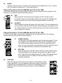
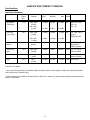
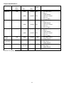
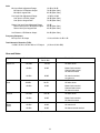
TM
AAM 802/1602
User Manual
Intended to alert the user to the presence of uninsulated “dangerous voltage” within the product’s
enclosure that may be of sufficient magnitude to constitute a risk of electric shock to persons.
Intended to alert the user of the presence of important operating and maintenance (servicing)
instructions in the literature accompanying the product.
CAUTION: Risk of electrical shock — DO NOT OPEN!
CAUTION: To reduce the risk of electric shock, do not remove cover. No user serviceable parts inside. Refer
servicing to qualified service personnel.
WARNING: To prevent electrical shock or fire hazard, do not expose this appliance to rain or moisture. Before
using this appliance, read the operating guide for further warnings.
Este símbolo tiene el propósito, de alertar al usuario de la presencia de “(voltaje) peligroso” sin aislamiento dentro de la caja del producto y que puede tener una magnitud suficiente como para constituir
riesgo de descarga eléctrica.
Este símbolo tiene el propósito de alertar al usario de la presencia de instruccones importantes sobre la
operación y mantenimiento en la información que viene con el producto.
PRECAUCION: Riesgo de descarga eléctrica ¡NO ABRIR!
PRECAUCION: Para disminuír el riesgo de descarga eléctrica, no abra la cubierta. No hay piezas útiles dentro.
Deje todo mantenimiento en manos del personal técnico cualificado.
ADVERTENCIA: Para evitar descargas eléctricas o peligro de incendio, no deje expuesto a la lluvia o humedad
este aparato Antes de usar este aparato, Iea más advertencias en la guía de operación.
Ce symbole est utilisé dans ce manuel pour indiquer à l’utilisateur la présence d’une tension dangereuse
pouvant être d’amplitude suffisante pour constituer un risque de choc électrique.
Ce symbole est utilisé dans ce manuel pour indiquer à l’utilisateur qu’il ou qu’elle trouvera d’importantes
instructions concernant l’utilisation et l’entretien de l’appareil dans le paragraphe signalé.
ATTENTION: Risques de choc électrique — NE PAS OUVRIR!
ATTENTION: Afin de réduire le risque de choc électrique, ne pas enlever le couvercle. Il ne se trouve à l’intérieur
aucune pièce pouvant être reparée par l’utilisateur. Confiez I’entretien et la réparation de l’appareil à un réparateur
Peavey agréé.
AVERTISSEMENT: Afin de prévenir les risques de décharge électrique ou de feu, n’exposez pas cet appareil à la
pluie ou à l’humidité. Avant d’utiliser cet appareil, lisez attentivement les avertissements supplémentaires de ce
manuel.
Dieses Symbol soll den Anwender vor unisolierten gefährlichen Spannungen innerhalb des Gehäuses
warnen, die von Ausreichender Stärke sind, um einen elektrischen Schlag verursachen zu können.
Dieses Symbol soll den Benutzer auf wichtige Instruktionen in der Bedienungsanleitung aufmerksam
machen, die Handhabung und Wartung des Produkts betreffen.
VORSICHT: Risiko — Elektrischer Schlag! Nicht öffnen!
VORSICHT: Um das Risiko eines elektrischen Schlages zu vermeiden, nicht die Abdeckung enfernen. Es befinden
sich keine Teile darin, die vom Anwender repariert werden könnten. Reparaturen nur von qualifiziertem
Fachpersonal durchführen lassen.
ACHTUNG: Um einen elektrischen Schlag oder Feuergefahr zu vermeiden, sollte dieses Gerät nicht dem Regen
oder Feuchtigkeit ausgesetzt werden. Vor Inbetriebnahme unbedingt die Bedienungsanleitung lesen.
2
ENGLISH
AAM™ 802/1602 Compact Console
The all new AAM 802/1602 Series mixer is a compact unit that can be used in sound reinforcement
or recording applications. Its low noise design and extensive list of features make it the ideal mixing
console for almost any application.
NOTE: This manual covers all AAM 802/1602 Series mixers. Differences in the two models are
noted where applicable.
GENERAL DESCRIPTION:
The AAM 802/1602 Series mixers share the same master section. The various models provide
different channel configurations in order to suit the needs of the user. The following features are
found throughout the series.
FEATURES:
• Balanced (XLR) and Unbalanced (1/4") Left and Right Outputs (mains)
• Balanced (XLR) and Unbalanced (1/4") Mon 1 and 2 Outputs (monitors)
• Balanced (XLR) and Unbalanced (1/4") Mono Outputs (mono mains)
• Two Effects Sends (1 and 2) each with stereo Returns (L and R)
• Mic (XLR) and Line (1/4") Inputs for all input channels
• Insert jacks (1/4") on all input channels except Super and Stereo input channels
• Pad and Polarity switches on Super Mic input channels
• Stereo (L and R) line inputs (1/4") on Stereo input channels
• PFL function on all input channels and on Monitor 1 and 2
• Low noise mic preamps on all input channels
• Mute/Peak and Signal/PFL indicators on all input channels and on Monitor 1 and 2
• Stereo LED level indicators for L/R mains
• Mute switch and 3-band EQ on each input channel
• Sweepable mid-EQ control on all input channels (except Stereo channels)
• Seperate Mic and Line Gain controls on Stereo Channels
• Stereo RCA Tape In/Out Jacks
• Stereo Headphone Output with level control
• Switchable, global +48 V Phantom Power with LED indicator
POWER
This section describes the application of power to your AAM 802/1602 mixer. Please note all caution
signs for your safety as well as your equipment. The following features are found on the rear
panel of the unit unless otherwise noted.
1.
Removable AC Power Cord
This receptacle is for the IEC line cord (included),
which provides AC power to the unit. Connect the
1
line cord to this connector and to a properly
grounded AC supply. Damage to the equipment may
occur if an improper line voltage is used. (See
2
voltage marking on unit.) Never remove or cut the
ground pin of the line cord plug. This unit is supplied with a properly rated line cord. When lost or
damaged, replace this cord with one of the proper ratings. NOTE: FOR UK ONLYAs the colors
of the wires in the mains lead of this apparatus may not correspond with the colored markings
identifying the terminals in your plug, proceed as follows: (1) The wire which is colored green and
3
yellow must be connected to the terminal which is marked by the letter E, or by the earth symbol, or
colored green or green and yellow. (2) The wire which is colored blue must be connected to the terminal which is marked with the letter N, or the color black. (3) The wire which is colored brown must
be connected to the terminal which is marked with the letter L or color red.
2.
POWER:
This is the mixer’s main power switch. To turn the power on place the switch in the (|)
position. Place the switch in the (O) position to turn the power off. The power-on LED
indicator will light when the unit is on.
3.
POWER LED:
This LED illuminates to indicate that power has been applied to
the unit.
3
INPUTS AND OUTPUTS
You must first connect your AAM 802/1602 to outboard equipment in order to better understand the
remaining functions. This section describes the inputs and outputs found on the rear of the AAM
802/1602 mixer. The channel inputs are found in the “Input Channels” section of this manual in order
to help you understand the internal signal flow of your AAM 802/1602 mixer.
Warning: Always connect to the following jacks while the AAM 802/1602 and its associated
equipment are turned off. It is also recommended to turn the Master and Monitor Faders (see
“Master Section”) completely down before the unit is turned on to ensure that any signal being
applied to the AAM 802/1602 mixer is defeated before the outputs.
9
4.
RETURN INPUTS:
1/4" balanced (TRS) high impedance input for high
level signals. These are designed for effect returns,
but can be used for additional stereo inputs. The tip
is the positive input, which should also be used for
unbalanced inputs. The Left/Mono input supplies
signal to both the left and right inputs if there is no
input connected to the right input jack.
5.
EFFECTS OUT:
1/4" unbalanced TS output jack of the corresponding
Effects mix. It can be used to feed an external
monitor system or effect unit.
5
4
8
7
6
6.
MONITOR 1 OUT:
1/4" unbalanced TS and a fully balanced XLR output of the Monitor 1 mix designed to feed an
external monitor system. (The tip is positive.) The output level is set by the individual channel
Monitor 1 send controls and by the master Monitor 1 fader (33). Both outputs can be used
simultaneously.
7.
MONITOR 2 OUT:
1/4" unbalanced TS and a fully balanced XLR output of the Monitor 2 mix designed to feed an
external monitor system. (The tip is positive.) The output level is set by the individual channel
Monitor 2 send controls and by the master Monitor 2 fader (34). Both outputs can be used
simultaneously.
4
8.
MAIN LEFT/RIGHT OUTPUTS:
1/4" TS and a fully balanced XLR output of the Left and Right mixes. The output level is set
by the Master Left and Right Faders (35). Both outputs can be used simultaneously.
9.
MAIN MONO OUTPUTS:
1/4" TS and a fully balanced XLR output of the mono mix (left/right summed). The output
level is set by the Master Mono Fader (36).
MASTER SECTION
The Master Section contains all the master level controls, effects send/return controls, headphone
and tape controls as well as the level meters. It is important that this area of the board be set up
properly in order to get the most from the Input Channel Section of your AAM 802/1602.
Warning: Keep all faders at the lowest position until you are ready to set your final levels.
Having the master faders in any other position while setting up the Input Channel Section could
result in accidental signal overload and/or sudden burst of signal at high levels.
11
16
12
17
10.
TAPE INPUT/OUTPUT:
The Tape Input jacks are set up for a
-10 dBV input from a stereo tape deck
or CD player. The output jacks can
provide a +4 dBu output signal to a
stereo tape deck. This output is the
same as the L/R mains.
11.
TAPE TO MONITOR 1 LEVEL:
Adjusts the level of the Tape Input
signal (10) supplied to the Monitor 1
mix. This control is independent of the
Tape L/R Level.
10
18
13
14
15
12.
TAPE TO MONITOR 2 LEVEL:
Adjusts the level of the Tape Input signal (10) supplied to the Monitor 2 mix. This control is
independent of the tape L/R level.
13.
TAPE TO L/R LEVEL:
Adjusts the level of the Tape Input signal (10) supplied to the L/R mix.
14.
PHANTOM POWER SWITCH:
Applies 48VDC voltage to all of the input XLR connectors. If phantom power is used, do not
connect unbalanced dynamic microphones or other devices to the XLR inputs that cannot
handle this voltage. (Some wireless receivers may be damaged. Consult their manuals.) The
line input jacks (38) are not connected to the 48V supply and are safe for all inputs (balanced
or unbalanced).
15.
PHANTOM POWER LED:
This LED illuminates to indicate that phantom power has been switched on by the Phantom
Power Switch (14).
5
16.
HEADPHONE OUTPUT:
This stereo jack (TRS) provides the signal to drive stereo headphones. The level is set by the
Headphone Level control (17). Tip= Left, Ring= Right, Shield= Ground.
17.
HEADPHONE/PFL LEVEL:
Adjusts the level of the Headphone Output. The source changes from the L-R output to the
PFL mix whenever the PFL is active.
PFL ACTIVE:
This LED blinks when the PFL is active and its signal is overriding the standard L-R mix in
the Headphone and at the L/R meters. The signals that are present in the PFL mix can be
located by the individually illuminated channel PFL LEDs.
18.
19
20
23
25
22
26
RETURN 1 TO MONITOR 1:
Sets the level of the Return 1 signal (effects)
that is added to the Monitor 1 mix. This is a
mono mix of the left and right signals.
20.
RETURN 1 TO MONITOR 2:
Sets the level of the Return 1 signal (effects)
that is added to the monitor 2 mix. This is a
mono mix of the left and right signals.
21.
RETURN 1 PAN:
Sets the Return1 position in the L-R stereo
field.
27
24
21
19.
29
28
22.
RETURN 1 TO L/R:
Sets the level of the Return 1 signal that is added to the L/R mix.
23.
RETURN 2 TO MONITOR 1:
Sets the level of the Return 2 signal (effects) that is added to the Monitor 1 mix. This is a
mono mix of the left and right signals.
24.
RETURN 2 TO MONITOR 2:
Sets the level of the Return 2 signal (effects) that is added to the monitor 2 mix. This is a
mono mix of the left and right signals.
25.
RETURN 2 PAN:
Sets the Return 2 position in the L-R stereo field.
26.
RETURN 2 TO L/R:
Sets the level of the Return 2 signal that is added to the L/R mix.
27.
EFFECTS 1 SEND:
Adjusts the level of the Effects 1 mix sent to the Effects 1 Output (5). Unity gain is at the
center detent position and +10 dB of gain in maximum.
28.
EFFECTS 2 SEND:
Adjusts the level of the Effects 2 mix sent to the Effects 2 Output (5). Unity gain is at the
center detent position and +10 dB of gain in maximum.
6
30
29.
LED METERS:
Two 12-segment LED arrays monitor the levels of the main
L/R outputs. The 0 dB reference level corresponds to
+4 dBu at the 1/4" jacks and XLR. (See 8.)
30.
MONITOR PEAK LED:
Indicates that the monitor mix level is nearing the overload
point. It illuminates at +19 dBu and warns that gain or EQ
boost should be reduced. There is roughly 2 dB of
headroom remaining when it lights.
31
32
33
34
35
36
31.
MONITOR SIGNAL/PFL LED:
Normally indicates that a signal is present in the monitor of –20 dBu or greater. If the Monitor
PFL switch (32) is depressed, it lights continuously to indicate that the monitor mix has been
assigned to the PFL mix.
32.
MONITOR PFL Switch:
Connects the monitor’s pre-fader signal to the PFL mix and switches the headphone source
from the L/R mix to the PFL mix.
33.
MONITOR 1 FADER:
Sets the overall level of the monitor signal that is sent to the Monitor 1 Output jacks (6). The
optimum setting for this control is the “0” (unity gain) position.
34.
MONITOR 2 FADER:
Sets the overall level of the monitor signal that is sent to the Monitor 2 Output jacks (7). The
optimum setting for this control is the “0” (unity gain) position.
35.
MASTER LEFT/RIGHT FADERS:
Master L/R level controls. Since the tape and headphone outputs come from this mix, they
will also be affected by its adjustment. The output levels are monitored by the left and right
meters. The optimum setting for this control is the “0” (unity gain) position.
36.
MONO OUTPUT FADER:
Sets the output of the Mono (L+R) signal found at the Mono Output (9).
7
INPUT CHANNELS
This section describes the many features found on the input channels. The AAM 802/1602 Series
mixer you have purchased utilizes multiple channel configurations. Some channels do differ from
others. It is important that you recognize these differences in order to take advantage of each
channel’s features and avoid confusion.
Channel Functions 1 — 6 for AAM 802 and 1 — 14 for 1602 :
37.
MIC INPUT:
XLR balanced low impedance channel input optimized for a microphone
or other low impedance source. Pin 2 is the positive input. Because of
the wide range of gain adjustment, signal levels up to +10 dBu
can be accommodated.
38.
LINE INPUT:
1/4" balanced (TRS) high impedance input for high level signals. The tip
is the positive input, which should also be used for unbalanced inputs.
This input is connected through a 20 dB pad to the MIC input (37). The
two inputs cannot be used simultaneously.
39
38
37
39.
INSERT: Channels (1 — 4 for AAM 802) (1 — 4 for 1602)
1/4" stereo (TRS) jack which allows an external device to be inserted into the
signal path before the tone equalization. The tip carries the send signal; the ring is
the return input. A switch in the jack normally connects the send to the return until
a plug is inserted. When plugged in partway (first click), the jack can be used as a
pre-amp output without interrupting the channel.
40
41
42
43
40.
GAIN:
Varies the input gain to allow for a wide dynamic range. It affects both the Line
and Mic inputs (Channels 1 — 6). Proper adjustment of the input gain will
maximize the signal-to-noise ratio. It should be set by depressing the PFL switch
(53) and adjusting it for a 0 dB level at the L-R meters. At this point there is
18 dB of headroom remaining.
44
45
46
41.
42.
44.
HI EQ:
A shelving type of active tone control that varies the treble frequency levels
+/-15 dB at 10 kHz. It is designed to remove noise or to add brilliance to the
signal, depending on the quality of the source.
MID EQ:
A bandpass (peak/notch) type of active tone control that varies the midrange
frequency levels +/-15 dB. On the first six channels of the AAM 802/1602, first 14
channels - AAM 802/1602), the frequency of the boost or cut is set by the Mid
Frequency control (43). The other channels have a fixed frequency of 850 Hz.
FREQUENCY (Not found on Stereo Mic Channels):
Sets the frequency affected by the Mid control (42). The range is 200 Hz to
6000 Hz.
8
47
48
49
50
51
52
53
54
45.
LOW EQ:
A shelving type of active tone control that varies the bass frequency levels +/-15 dB at 70 Hz.
It will add depth to thin signals or clean up muddy ones.
46.
MON 1:
Adjusts the level of the channel signal (pre-EQ) that is added to the Monitor 1 mix. This is a
mono mix of the left and right signals in the stereo channels. The center detent is the unity
gain position.
47.
MON 2:
Adjusts the level of the channel signal (pre-EQ) that is added to the Monitor 2 mix. This is a
mono mix of the left and right signals in the stereo channels. The center detent is the unity
gain position.
48.
EFFECTS 1:
Adjusts the level of the channel signal that is added to the Effects 1 mix. It is post-fader,
designed for use as an effects send, that can also be used for another monitor send. This
is a mono mix of the left and right signals. The center detent is the unity gain position.
49.
EFFECTS 2:
Adjusts the level of the channel signal that is added to the Effects 2 mix. It is post-fader,
designed for use as an effects send, that can also be used for another monitor send. This
is a mono mix of the left and right signals. The center detent is the unity gain position.
50.
PAN:
Sets the channel's position in the L-R stereo field.
51.
MUTE:
Mutes all channel bus sends (Mon1, Mon2, EFX 1,EFX 2, Left and Right) when depressed.
The PFL signal is independent of this switch, and can be used to check the channel and
adjust its input gain even when muted. The Mute/Peak LED will glow red continuously when
the corresponding channel is muted.
52.
MUTE/PEAK LED (red):
Normally indicates that the channel signal level is nearing the overload point. This circuit
monitors the input gain, equalization, and post-fader stages for overload. It illuminates at
+19 dBu and warns that gain or EQ boost should be reduced. There is roughly 2 dB of
headroom remaining when it lights. If the Mute switch (50) is depressed, it lights continuously
to indicate that this channel has been muted.
53.
SIGNAL/PFL LED (yellow):
Normally indicates that a signal is present in the channel of –20 dBu or greater. If the PFL
switch (53) is depressed, it lights continuously to indicate that this channel has been
assigned to the PFL mix.
54.
PFL:
Connects the channel’s pre-fader signal to the PFL mix and switches the headphone source
from the L-R mix to the PFL mix. It also connects the PFL signal to the L-R meters to aid in
the setting of the input gain (40). The Signal/PFL LED will illuminate when this switch is
pressed to identify the PFL source.
9
54.
FADER:
Channel output level control. The level of the channel can be adjusted from off to +10 dB of
gain. The optimum setting is the “0” (unity gain) position.
Channel Functions 5 & 6 for AAM 802 and 13 & 14 for 1602:
In these two channels all controls are identical to the previous channels with the exception of the
insert jack. It is replaced by pad and polarity switches.
55.
PAD:
When pressed it attenuates the input signal by 20 dB. This will increase
the dynamic range to accommodate a higher input level before clipping which
may be necessary when close miking loud guitar amplifiers or drum kits.
56.
POLARITY:
When pressed it reverses the phase of the input signal. This will compensate for
an out of phase input that would otherwise cause frequency cancellations in the
mix. (Often needed for drum mics where both sides of the drum head are picked
up in multiple mic situations.)
55
56
Channel Functions 7 & 8 for AAM 802 and 15 & 16 for 1602:
The Mic and Line inputs of these stereo channels can be used simultaneously. The following
features are found only on the the stereo channels.
57.
STEREO INPUTS:
1/4" balanced (TRS) high impedance input for high level signals. The tip
is the positive input, which should also be used for unbalanced inputs.
The Left/Mono Input supplies signal to both the left and right inputs if
there is no input connected to the right input jack. If the channel's input is
mono, the signal should be connected to the Left/Mono Input .
58.
MIC GAIN:
Varies the input gain of the Mic Input to allow for a wide dynamic range.
Proper adjustment of the input gain will maximize the signal to noise
ratio. It should be set by depressing the PFL switch (53) and adjusting it
for a 0 dB level at the L-R meters. At this point there is 18 dB of
headroom remaining.
57
59.
LINE GAIN:
Varies the input gain of the Line Input to allow for a wide dynamic range.
Proper adjustment of the input gain will maximize the signal to noise ratio.
It should be set by depressing the PFL switch (53) and adjusting it for a
0 dB level at the L-R meters. At this point there is 18 dB of headroom
remaining.
58
59
10
AAM 802/1602 COMPACT CONSOLE
Specifications:
Input Specifications:
Function
Microphone
(150 ohms)
Line Input
(10 k ohms)
Input Z
(ohms)
Min
Input Gain
Settings
2.2 k
Max. Gain
(58 dB)
Min. Gain
(10 dB)
10 k
Min**
Input Levels
Nominal*
Max
Bal/
Connector
UnBal.
-74 dBu
-54 dBu
-37 dBu
Bal.
XLR: Pin 1 Gnd,
Pin 2 (+),
Pin 3 (-)
-27 dBu
-6 dBu
+10 dBu
Max. Gain
(38 dB)
-54 dBu
-34 dBu
-17 dBu
Bal.
1/4" TRS; Tip (+),
Ring (-),
Sleeve Ground
Min. Gain
(-10 dB)
-6 dBu
+14 dBu
+31 dBu
+22 dBu Unbal. 1/4" TRS; Tip Send,
Ring Return,
Sleeve Ground
Insert
Return
10 k
N/A
(0) dB)
-16 dBu
+4 dBu
Stereo Line
Input
10 k
Max. Gain
(30 dB)
-26 dBu
+4 dBu
+22 dBu
Unbal. 1/4" TS; Tip (+),
Sleeve Ground
Aux Returns
10 k
N/A
(0 dB)
-26 dBu
+4 dBu
+22 dBu
Unbal. 1/4" TS; Tip (+)
Sleeve Ground
Tape
10 k
N/A
(10 dB)
-26 dBu
-10 dBV
+12 dBu Unbal. RCA Phono
0 dBu=0.775 V (RMS)
** Min. input level (sensitivity) is the smallest signal that will produce nominal output (+4 dBu) with channel and master
level controls set for maximum gain.
* Nominal settings are defined as all controls set a 0 dB (or 50% rotation for rotary pots) except the gain adjustment pot,
which is as specified.
11
Output Specifications:
Function
Main L/R
Monitors
Mono
Minimum
Load
Ohms
600
600
600
Output Level
Min**
Bal/
UnBal.
Connector
Max
+4 dBu
+22 dBu
Bal.
1/4" TRS: Tip (+),
Ring (-)
Sleeve Ground
+4 dBu
+22 dBu
Bal.
XLR: Pin 1 Ground
Pin 2 (+),
Pin 3 (-), (Bal.)
+4 dBu
+22 dBu
Bal.
1/4" TRS: Tip (+)
Ring (-),
Sleeve Ground
+4 dBu
+22 dBu
Bal.
XLR: Pin 1 Ground,
Pin 2 (+),
Pin 3 (-), (Bal.)
+4 dBu
+22 dBu
Bal.
1/4" TRS: Tip (+),
Ring (-),
Sleeve Ground
+4 dBu
+22 dBu
Bal.
XLR: Pin 1 Ground
Pin 2 (+),
Pin 3 (-), (Bal.)
Effects
Sends
600
+4 dBu
+22 dBu
Unbal.
1/4" Phone: Tip (+),
Sleeve Ground
Channel
Insert Send
600
+4 dBu
+22 dBu
Unbal.
1/4" TRS: Tip Send,
Ring Return,
Sleeve Ground
+4 dBu
(No load)
+22 dBu
Unbal.
1/4: TRS: Tip Left,
Ring Right,
Sleeve Ground
+4 dBu
+22 dBu
Unbal.
RCA Phono
Headphone
Tape
8
2.2 k
0 dBu=0.775 V (RMS)
12
Gain:
Mic Input Gain Adjustment Range:
Mic Input to L/R Balance Output
Mic Input Longest Path
10 dB to 58 dB
78 dB (Max. Gain)
93 dB (Max. Gain)
Line Input Gain Adjustment Range:
Line Input to L/R Bal. Output
Line Input to longest Path
-10 dB to 38 dB
60 dB (Max. Gain)
73 dB (Max. Gain)
Stereo Line Input Gain Adjustment Range
Stereo Line Input to L/R Balance Output
Stereo Line Input Longest Path
10 dB
36 dB (Max. Gain)
46 dB (Max. Gain)
Aux Return to L/R Balance Output
34 dB (Max. Gain)
Frequency Response:
Mic Input to L-R Output
11 Hz to 42 kHz +0 dB/-1 dB
Total Harmonic Distortion (THD):
<0.008% 20 Hz to 20 kHz Mic to L-R Output
(10 Hz to 80 kHz BW)
Hum and Noise:
Output
Master L/R
Mono
Monitors
Effects
Sends
Residual Noise
S/N Ratio
Ref. 0 dBu
Test Conditions
-100 dBu
104 dB
All faders down
-88 dBu
92 dB
Master fader nominal,
Channel faders down,
All channels muted
-84 dBu
88 dB
All controls nominal,
mic gain min.
-90 dBu
94 dB
All faders down
-88 dBu
92 dB
Master fader nominal,
Channel faders down,
All channels muted
-102 dBu
106 dB
-90 dBu
94 dB
Master fader nominal,
All channels muted
-95 dBu
99 dB
All controls off
-82 dBu
86 dB
All channel sends nominal
(Hum and Noise Measurements: 22 Hz to 22 kHz BW)
13
All faders down
Equivalent Input Noise (EIN):
-129 dBu (Input terminated with 150 ohms)
Crosstalk:
>80 dB adjacent input channels (20 Hz — 20 kHz)
>70 dB left to right outputs (20 Hz — 20 kHz)
Common Mode Rejection Ration (Mic Input):
50 dB min. (20 Hz to 20 kHz)
70 dB type @ 1 kHz
Meters:
12 segment, peak reading
(0 dB = +4 dBu)
Signal/Overload Indicators:
Red LED lights 2 dB below clipping
Dimensions (H x W x D):
AAM 802: 5.500" x 15.000" x 16.500" (13.97 cm x 38.10 cm x 41.91 cm)
AAM 1602: 5.500" x 23.000" x 16.500" (13.97 cm x 58.42 cm x 41.91 cm)
Weight:
AAM 802: 13.7 lbs. (6.21 kg)
AAM 1602: 19.7 lbs. (8.93 kg)
14
15
AAM 802/1602 Series
BLOCK DIAGRAM
NOTES:
16
NOTES:
17
IMPORTANT SAFETY INSTRUCTIONS
WARNING: When using electric products, basic cautions should always be followed, including the following:
1.
Read these instructions.
2.
Keep these instructions.
3.
Heed all warnings.
4.
Follow all instructions.
5.
Do not use this apparatus near water. For example, near or in a bathtub, swimming pool, sink, wet basement, etc.
6.
Clean only with a damp cloth.
7.
Do not block any of the ventilation openings. Install in accordance with manufacturer’s instructions. It should not be placed flat against a wall
or placed in a built-in enclosure that will impede the flow of cooling air.
8.
Do not install near any heat sources such as radiators, heat registers, stoves or other apparatus (including amplifiers) that produce heat.
9.
Do not defeat the safety purpose of the polarized or grounding-type plug. A polarized plug has two blades with one wider than the other. A
grounding type plug has two blades and a third grounding plug. The wide blade or third prong is provided for your safety. When the provided
plug does not fit into your inlet, consult an electrician for replacement of the obsolete outlet. Never break off the grounding. Write for our free
booklet “Shock Hazard and Grounding”. Connect only to a power supply of the type marked on the unit adjacent to the power supply cord.
10. Protect the power cord from being walked on or pinched, particularly at plugs, convenience receptacles, and the point they exit from the
apparatus.
11. Only use attachments/accessories provided by the manufacturer.
12. Use only with a cart, stand, tripod, bracket, or table specified by the manufacturer, or sold with the apparatus. When a cart is used, use caution
when moving the cart/apparatus combination to avoid injury from tip-over.
13. Unplug this apparatus during lightning storms or when unused for long periods of time.
14. Refer all servicing to qualified service personnel. Servicing is required when the apparatus has been damaged in any way, such as powersupply cord or plug is damaged, liquid has been spilled or objects have fallen into the apparatus, the apparatus has been exposed to rain or
moisture, does not operate normally, or has been dropped.
15. If this product is to be mounted in an equipment rack, rear support should be provided.
16. Exposure to extremely high noise levels may cause a permanent hearing loss. Individuals vary considerably in susceptibility to noise-induced
hearing loss, but nearly everyone will lose some hearing if exposed to sufficiently intense noise for a sufficient time. The U.S. Government’s
Occupational and Health Administration (OSHA) has specified the following permissible noise level exposures:
Duration Per Day In Hours
8
6
4
3
2
1 1/2
1
1/2
1/4 or less
Sound Level dBA, Slow Response
90
92
95
97
100
102
105
110
115
According to OSHA, any exposure in excess of the above permissible limits could result in some hearing loss. Ear plugs or protectors to the ear
canals or over the ears must be worn when operating this amplification system in order to prevent a permanent hearing loss, if exposure is in excess
of the limits as set forth above. To ensure against potentially dangerous exposure to high sound pressure levels, it is recommended that all persons
exposed to equipment capable of producing high sound pressure levels such as this amplification system be protected by hearing protectors while
this unit is in operation.
SAVE THESE INSTRUCTIONS!
18
Architectural Acoustics®
PEAVEY ELECTRONICS CORPORATION LIMITED WARRANTY
Effective Date: July 1, 1998
What This Warranty Covers
Your Peavey Warranty covers defects in material and workmanship in Peavey products purchased and serviced in the U.S.A. and Canada.
What This Warranty Does Not Cover
The Warranty does not cover: (1) damage caused by accident, misuse, abuse, improper installation or operation, rental, product modification or
neglect; (2) damage occurring during shipment; (3) damage caused by repair or service performed by persons not authorized by Peavey; (4) products
on which the serial number has been altered, defaced or removed; (5) products not purchased from an Authorized Peavey Dealer.
Who This Warranty Protects
This Warranty protects only the original retail purchaser of the product.
How Long This Warranty Lasts
The Warranty begins on the date of purchase by the original retail purchaser. The duration of the Warranty is as follows:
Product Category
Duration
MediaMatrix® DPU, (Excluding Frames), Cinema Processors,
Power Amplifiers, Pre-Amplifiers, Mixers,
Electronic Crossovers and Equalizers
5 years
Loudspeakers
5 years
Microphones
2 years
Frames
1 year
Speaker Components (incl. speakers, baskets, drivers,
diaphragm replacement kits and passive crossovers)
and all Accessories
1 year
What Peavey Will Do
We will repair or replace (at Peavey's discretion) products covered by warranty at no charge for labor or materials. If the product or component must
be shipped to Peavey for warranty service, the consumer must pay initial shipping charges. If the repairs are covered by warranty, Peavey will pay the
return shipping charges.
How To Get Warranty Service
(1) Take the defective item and your sales receipt or other proof of date of purchase to your Authorized Peavey Dealer or Authorized Peavey
Service Center.
OR
(2) Ship the defective item, prepaid, to Peavey Electronics Corporation, International Service Center, 412 Highway 11 & 80 East, Meridian, MS 39301
or Peavey Canada Ltd., 95 Shields Court, Markham, Ontario, Canada L3R 9T5. Include a detailed description of the problem, together with a copy of
your sales receipt or other proof of date of purchase as evidence of warranty coverage. Also provide a complete return address.
OR
(3) All MediaMatrix® Frames needing repair, should be shipped prepaid to Peavey Electronics Corporation, International Service Center, 412 Highway
11 & 80 East, Meridian, MS 39301
Limitation of Implied Warranties
ANY IMPLIED WARRANTIES, INCLUDING WARRANTIES OF MERCHANTABILITY AND FITNESS FOR A PARTICULAR PURPOSE, ARE LIMITED
IN DURATION TO THE LENGTH OF THIS WARRANTY.
Some states do not allow limitations on how long an implied warranty lasts, so the above limitation may not apply to you.
Exclusions of Damages
PEAVEY'S LIABILITY FOR ANY DEFECTIVE PRODUCT IS LIMITED TO THE REPAIR OR REPLACEMENT OF THE PRODUCT, AT PEAVEY'S
OPTION. IF WE ELECT TO REPLACE THE PRODUCT, THE REPLACEMENT MAY BE A RECONDITIONED UNIT. PEAVEY SHALL NOT BE
LIABLE FOR DAMAGES BASED ON INCONVENIENCE, LOSS OF USE, LOST PROFITS, LOST SAVINGS, DAMAGE TO ANY OTHER EQUIPMENT
OR OTHER ITEMS AT THE SITE OF USE, OR ANY OTHER DAMAGES WHETHER INCIDENTAL, CONSEQUENTIAL OR OTHERWISE, EVEN IF
PEAVEY HAS BEEN ADVISED OF THE POSSIBILITY OF SUCH DAMAGES.
Some states do not allow the exclusion or limitation of incidental or consequential damages, so the above limitation or exclusion may not
apply to you.
This Warranty gives you specific legal rights, and you may also have other rights which vary from state to state.
If you have any questions about this warranty or service received or if you need assistance in locating an Authorized Service Center, please contact
the Peavey International Service Center at (601) 483-5365 / Peavey Canada Ltd. at (905) 475-2578.
Features and specifications subject to change without notice.
19
Features and specifications subject to change without notice.
Peavey Electronics Corporation • 711 A Street • Meridian • MS • 39301
(601) 483-5376 • FAX (601) 486-1678 • http://.aapeavey.com
©2001
80304861
Printed in the U.S.A. 4/01