1
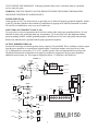
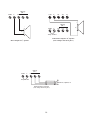
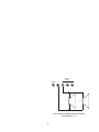
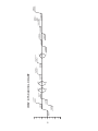
IRM
8150
Powered Mixer
1
Intended to alert the user to the presence of uninsulated "dangerous voltage" within the product's enclosure
that may be of sufficient magnitude to constitute a risk of electric shock to persons.
Intended to alert the user of the presence of important operating and maintenance (servicing) instructions in the
literature accompanying the product.
CAUTION: Risk of electrical shock – DO NOT OPEN!
CAUTION: To reduce the risk of electric shock, do not remove cover. No user serviceable parts inside. Refer servicing to
qualified service personnel.
WARNING: To prevent electrical shock or fire hazard, do not expose this appliance to rain or moisture. Before using this
appliance, read the operating guide for further warnings.
Thank you for purchasing the Peavey IRM™ 8150 mixer amplifier. This is an eight-channel,
easy-to-use, powered mixer.
Your IRM™ 8150 features a rugged, heavy-gauge, cold-rolled steel and aluminum chassis,
finished in oven-cured epoxy for toughness and screen-printed utilizing the latest photographic film and U.V.-cured ink technology for razor-sharp, hard-wearing control I.D. and
calibration graphics.
Every on-board component has been carefully chosen to deliver the highest possible performance. Precision, professional reliability and absolute minimal operating noise characteristics are among the initial criteria used during the process of selecting the components that
ensure that your IRM™ 8150 becomes an indispensable addition to your performance equipment.
All printed circuit boards are constructed from rugged, U.S. military-spec material, using the
latest automated assembly technology, wave solder, and computer-controlled "all-faultsanalyzed-and-corrected" Q.A. procedures.
Each channel features front panel main and monitor level controls, as well as high, mid, low
equalization and AUX send controls. Every input channel has a studio-quality low impedance (XLR-type input) microphone input as well as a 1/4" line input. Switchable
+48 V phantom power is provided.
The unit features a 150 watt power amplifier.
2
CHANNEL SECTION:
LEVEL (1)
Controls the channel output level. This signal is routed via the main bus to the main level control. The channel
level also affects the signal to the AUX send control.
MONITOR (MON.) (2)
Controls the channel monitor mix level. This is independent of all other channel controls. Controls the amount of
signal from a particular channel in the monitor mix. This signal is routed to the Mon. control in the master
section.
LOW EQ (3)
Controls the channel low EQ level. An active tone control (shelving type, ±12 dB) that varies the low frequency
range.
MID EQ (4)
Controls the channel mid EQ level. An active tone control (peak/notch, ±12 dB) that adjusts the mid frequency
range.
HIGH EQ (5)
Controls the channel high EQ level. An active tone control (shelving type, ±12 dB) that varies the high frequency
range.
3
AUX SEND (6)
Controls the channel AUX drive level. This signal is routed to the AUX master control, where AUX send signals
from all channels are summed together. Controls amount of send from a particular channel to AUX output. The
channel level control also affects the signal from the AUX send.
MASTER SECTION:
POWER INDICATOR:
PILOT LIGHT LED (7)
Illuminates when AC power is being supplied to the amp.
9-BAND GRAPHIC EQ (8)
Provides +6 dB, -12 dB equalization at each center frequency. EQ boost is obtained by moving a particular EQ
band's slide control above the center line. EQ cut is obtained by moving a particular EQ band's slide control
below the center line.
OPERATION NOTE: This equalizer is designed to provide room equalization, feedback control and system
tone control. No amount of equalization will correct the response curve of a poor loudspeaker. Always begin
with all sliders in the "0" position and avoid excessively cutting large segments of the audio passband, which
would limit the system's dynamic range. Also, avoid boosting sliders excessively. This limits the headroom of
the amplifier and can cause clipping if excessive channel EQ boost is used simultaneously.
MAIN (9)
Controls the overall volume level of the main system. The signal from this control is available at the main output
(20). Under normal conditions this signal is also internally patched through the graphic EQ and power amplifier
so that this control sets the volume of the speakers connected to the output barrier strip (30). Maximum master
signal level is obtained by rotating this control fully clockwise. Minimum master signal level cut is obtained by
rotating this control fully counterclockwise.
MONITOR (10)
Controls the overall monitor mix level. Maximum monitor signal level is obtained by rotating this control fully
clockwise. Minimum monitor signal level is obtained by rotating this control fully counterclockwise. The monitor signal is supplied to the monitor output jack (21).
AUX (11)
Controls the signal level supplied to the AUX output jack (22). Maximum AUX signal level is obtained by
rotating this control fully clockwise. Minimum effects signal level is obtained by rotating this control fully
counterclockwise.
TAPE SECTION:
TAPE OUT LEVEL (12)
Controls the signal level at the tape out jacks (16). Signal is derived from the main output, but operation is
independent of the main master level control (9) and the graphic equalizer (8).
TAPE/AUX IN LEVEL (13)
When external signals are patched into the tape in jacks (15) or the auxiliary input (25), TAPE/AUX IN LEVEL
(13) provides control over the level of signals sent from these inputs to the main mix.
4
TAPE/AUX TO MON (14)
Controls the level of tape or AUX IN signal to be sent to the mon. bus. This signal will be mixed with channel
monitor signals.
TAPE OUT/TAPE IN: CAUTION
Before placing connected tape decks in the "record" mode, set the TAPE/AUX IN level control to "0" or off.
Most tape decks feed the input signal directly to the output when in record mode. This creates a "closed loop"
condition from the tape out to tape in jack which can affect the operational level or sonic quality of the system
and cause feedback.
TAPE IN (RCA TYPE) JACKS (15)
These two jacks provide a paralleled input for proper mono mixing of stereo tape deck outputs. For monaural
tape sources, use either jack.
TAPE OUT (RCA TYPE) JACKS (16)
These two jacks provide the same monaural signal to be supplied to the left and right inputs of a stereo tape deck.
Output level is determined by the TAPE OUT (12) level control.
REAR PANEL INPUT/OUTPUT SECTION:
BALANCED LOW IMPEDANCE INPUT (17)
For use with low impedance microphones or low-level sources equipped with an XLR connector.
5
LINE INPUT JACK (18)
For use with line level signal or compatible high Z microphones equipped with a 1/4" phone plug.
NOTE: These input jacks (17 & 18) are typical of each channel. It is possible to use both the mic and line inputs
on a single channel simultaneously. It is, however, unlikely that the gain matching of the mic and line will allow
this hookup to be useful. This practice is not recommended.
PHANTOM POWER ON/OFF (19)
This switch selects phantom power "ON" or "OFF" for all channels. Phantom power is on when the switch is in
the in position and off when the switch is in the out position. This switch should be activated for use with condenser-type microphones. Phantom voltage is +48 V DC on pins 2 and 3 referenced to pin 1.
MAIN OUTPUT (20)
This 1/4" jack provides a signal from the main system mix before the graphic equalizer. Used primarily to feed
an auxiliary amplifier/speaker system. (See wiring diagram).
MONITOR OUTPUT (21)
This 1/4" jack provides a signal from the MONITOR mix for an external monitor amplifier/speaker system. The
level is determined by the channel monitor and master monitor controls.
AUX OUTPUT (22)
This 1/4" jack provides a signal from the AUX mix for external effects or signal-processing equipment. This
output can also be used for other purposes if external effects are not required. These include building a separate
mix for recording or broadcasting.
GRAPHIC INPUT (23)
This 1/4" jack provides an input to the internal graphic equalizer/power amp. This is a switching jack: a signal
inserted here interrupts the normal signal path from the main bus into the equalizer.
OPERATION NOTE: This jack permits the equalizer to be switched away from its normal input and accept an
external signal to be equalized, such as the monitor output.
GRAPHIC OUT (24)
This 1/4" jack provides access to the output of the internal graphic equalizer. A plug inserted into this jack does
not switch the EQ output away from the input to the power amplifier.
AUXILIARY INPUT (25)
This 1/4" jack provides access to an input to the main mixing bus for patching in returns from external effects
devices, extra mixing channels, etc. Using this jack defeats both tape in jacks.
POWER AMP INPUT (26)
This 1/4" jack provides access to connect external line-level signals to the power amplifier.
OPERATION NOTE: This jack permits the internal power amplifier to be switched away from its normal input
and to accept external line-level signals.
AC POWER AND POWER AMPLIFIER OUTPUT SECTION:
FUSE (27)
The fuse is located within the cap of the fuseholder. If the fuse should fail, IT MUST BE REPLACED WITH
THE SAME TYPE AND VALUE IN ORDER TO AVOID DAMAGE TO THE EQUIPMENT AND TO PRE6
VENT VOIDING THE WARRANTY. If the amp repeatedly blows fuses, it should be taken to a qualified
service center for repair.
WARNING: THE FUSE SHOULD ONLY BE REPLACED WHEN THE POWER CORD HAS BEEN
DISCONNECTED FROM ITS POWER SOURCE.
POWER SWITCH (28)
Center position is OFF. Two ON positions are provided, one of which will properly ground the amplifier. Switch
to the ON side that yields the lowest amount of residual hum or popping noise when the instrument is touched.
220 and 240 volt models have a two-way on/off switch only.
LINE CORD (120 V PRODUCTS ONLY) (29)
For your safety, we have incorporated a three-wire line (mains) cable with proper grounding facilities. It is not
advisable to remove the ground pin under any circumstances. If it is necessary to use the equipment without
proper grounding facilities, suitable grounding adaptors should be used. Less noise and greatly reduced shock
hazard exist when the unit is operated with the proper grounded receptacles.
OUTPUT BARRIER STRIP (30)
Provided for connection of external speakers. Power output is 150 watts RMS. This is available as a direct output
from the power amplifier or as transformer isolated outputs. Transformer outputs can be used for an 8 ohm
(35 V) loudspeaker or used to drive 25 V or 70 V speaker systems. Only one output should be used at a time.
The balanced transformer isolated line level output is provided for connection to booster power amplifiers,
additional sound systems, etc. This output is designed to deliver 1 V RMS into a 600 ohm load.
CHANNEL 1-8
LEVEL
PHANTOM
POWER
LOW Z
MIC
INPUT
1
6.8K
6.8K
+48VDC
3 BAND EQ
MAIN BUS
MIC
PREAMP
Low
-
3
Mid
Hi
AUX
AUX BUS
2
+
MON BUS
600 OHM HI
MON
LINE
INPUT
600 OHM LO
GND
4 OHM
XFMR
AUX IN
AUX/TAPE
TO MON
N/C
POWER AMP
COMMON
OUTPUT
XFMR
PA IN
AUX/TAPE
TO MAIN
8 OHM
25 V
70 V
SPS
TAPE IN
9 BAND GRAPHIC EQUALIZER
MAIN OUT GR IN
GR OUT
MAIN BUS
MAIN
63 125
250 500Hz 1kHz 2kHz 4kHz 8kHz 16kHz
TAPE
TAPE OUT
MON
MON OUT
MON BUS
IRM 8150
AUX
™
AUX BUS
BLOCK DIAGRAM
AUX OUT
7
Maximum Channel Gain:
Low Z = 40 dB
Line = 20 dB
SPECIFICATIONS
NOTE: All specifications are typical unless
otherwise noted.
Nominal Input Level:
Low Z = -20 dBV
Line = 0 dBV
0 dBV = 1 volt RMS
0 dBu = .778 volts RMS
Minimum Input Level:
Low Z = -40 dBV
Line = -20 dBV
All specs are referenced to nominal output level
(0 dBV) unless otherwise noted.
All measurements are wideband 20 Hz to 20 kHz
unless otherwise stated.
Maximum Input Level:
Low Z = +6 dB
Line = +26 dB
All control settings are nominal (50% rotation) unless
otherwise noted.
Phantom Power:
+48 V DC
CHANNEL
Equivalent Input Noise:
-114.5 dBV @ 40 dB max gain
GRAPHIC EQUALIZER:
Filter Bandwidth:
1 octave
Frequency Response:
(to speaker outputs)
±1 dB 20 Hz to 20 kHz
Filter Frequencies:
(ISO Stds.)
63 Hz, 125 Hz, 250 Hz, 1 kHz, 2 kHz, 4 kHz, 8 kHz,
16 kHz
Distortion:
(1 kHz)
Less than .015%
Filter Q:
1.57
Input Impedance:
Low Z Bal = 1.7 K ohms
Line Input = 13 K ohms
Maximum Boost & Cut:
+ 6 dB, -12 dB
High EQ:
±12 dB @ 10 kHz minimum
center detent flat ±2 dB
Noise:
-100 dBV
Distortion:
(1 kHz)
Less than .005%
Mid EQ:
±12 dB @ 600 Hz minimum
center detent flat ±2 dB
Frequency Response:
±1 dB 7 Hz to 40 kHz
Low EQ:
±12 dB @ 50 Hz minimum
Center detent flat ±2 dB
Input Level:
Nom = 0 dBV (1.0 V RMS)
Max = +19 dBV ( 9 V RMS)
Nominal Channel Gain:
Low Z = 20 dB
Line = 0 dB
Output Level:
Nom = 0 dBV (1.0 V RMS)
Max = +19 dBV ( 9 V RMS)
Minimum Channel Gain:
Low Z = -69 dB
Line = -89 dB
Input Impedance:
10 K ohms
8
Output Impedance:
100 ohms
POWER AMP SECTION
Frequency Response:
+0, -1 dB 20 Hz to 20 kHz @ Rated Power (direct out)
+0, -1 dB 50 Hz to 20 kHz @ Rated Power (XFMR
outputs)
MASTER
Gain:
Main:
Monitor:
Tape:
Aux:
=
=
=
=
20 dB
15 dB
15 dB
15 dB
Rated Power:
Direct Out:
150 watts RMS @ 4 ohms
Maximum Output Level:
Main:
=
+18 dBV (8.0 V RMS)
Monitor:
=
+18 dBV (8.0 V RMS)
Tape:
=
+18 dBV (8.0 V RMS)
Aux:
=
+18 dBV (8.0 V RMS)
Nominal Headroom:
Main:
=
Monitor:
=
Tape:
=
Aux:
=
18 dB
18 dB
18 dB
18 dB
Output Impedance:
Main:
=
Monitor:
=
Tape:
=
Aux:
=
100 ohms
100 ohms
10 K ohms
100 ohms
XFMR Outputs:
150 watts RMS @ 8 ohms
150 watts RMS @ 25 V (4 ohms)
150 watts RMS @ 70 V (33 ohms)
1 V RMS into 600 ohms
Intermodulation Distortion:
Less than 0.1%, (10 mW to rated power, 250 Hz & 7
kHz, 4 ohms)
Total Harmonic Distortion:
Less than 0.1%
SPS™ Dynamic Range:
Greater than 26 dB
SPS™ Maximum Distortion:
Below 0.5% THD for 6 dB overload
Below 1% THD for 20 dB overload
Output Noise:
Residual: -100 dBV
(Master Level Down)
Bus: -94 dBV
(Master Nominal, All Channel Level Full CCW,
Aux Returns Down)
Nominal: -86 dBV
(All Controls Nominal, Low Z Input Terminated
150 ohms)
Hum & Noise:
-92 dB below 150 watts
Slew Rate:
15 V/µSec
Damping Factor:
Greater than 100 @ 1 kHz, 4 ohms
Input Sensitivity:
1 V RMS for 150 watts @ 4 ohms
Aux Input Impedance:
120 K ohms
Input Impedance:
19 K ohms
Aux Input Level:
Nom: 0 dBV
Max: +7 dBV
Min: -15 dBV
Power Requirements:
800 watts, 120 V AC, 60 Hz
Tape Input Level:
Nom: +4 dBV
Max: +11 dBV
Min: -10 dBV
9
Balanced
(600Ω)
XFMR
4Ω
GND
LO
COM
HI
8Ω
25V
70V
NC
+
Balanced
(600Ω)
–
XFMR
4Ω
GND
LO
HI
8Ω
–
4Ω
Jumper Installed
+
Transformer Output to 8Ω Speaker
(Note: Jumper must be in place.)
Direct Output to 4Ω Speaker
Balanced
(600Ω)
XFMR
4Ω
GND
LO
HI
Jumper Installed
To Booster, Amplifier, etc.
Balanced Output Connection
(Note: Jumper must be in place.)
10
Balanced
(600Ω)
XFMR
4Ω
GND
LO
HI
–
–
8Ω
8Ω
+
+
Direct Output to Multiple Speakers in Parallel.
Total Impedance = 4Ω
11
12
13
-70
-60
-50
-40
-30
-20
-10
dBV
0
10
20
30
CHANNEL INPUT
MINIMUM (1/4")
(-20 dBV)
CHANNEL INPUT
MINIMUM (XLR)
(GAIN -40 dBV)
CHANNEL INPUT
NOMINAL (XLR)
(GAIN -20 dBV)
CHANNEL INPUT
NOMINAL (1/4")
(0 dBV)
CHANNEL INPUT
MAX (XLR)
(+6 dBV)
CHANNEL INPUT
MAX (1/4")
(+ 26 dBV)
-12 dBV
CUT
50 HZ &10 kHz
CHANNEL
EQ
FLAT
+12 dBV
BOOST
-12 dBV
CUT
600 Hz
CHANNEL
EQ
FLAT
+12 dBV
BOOST
MAIN, MON, TAPE,
AUX OUTPUTS
(-0 dBV)
NOMINAL
GRAPHIC
INPUT/OUTPUT
LEVELS (+0 dBV)
NOMINAL
MAIN, MON, TAPE,
AUX OUTPUTS
(+18 dBV) MAXIMUM
IRM™ 8150 LEVEL CHART
-12 dBV
GRAPHIC
EQ
FLAT
+6 dBV
GRAPHIC INPUT/OUTPUT
LEVELS (+19 dBV)
MAXIMUM
AUX INPUT LEVEL
(-15 dBV) MINIMUM
AUX INPUT LEVEL
(0 dBV) NOMINAL
TAPE INPUT LEVEL
(-10 dBV) MINIMUM
AUX INPUT LEVEL
(+7 dBV) MAXIMUM
TAPE INPUT LEVEL
(+4 dBV) NOMINAL
TAPE INPUT LEVEL
(+11 dBV) MAXIMUM
POWER AMP INPUT
SENSITIVITY (0 dBV)
NOMINAL
HEADROOM
(MAIN, MONITOR,
TAPE, AUX)
(+18 dBV)
NOMINAL
POWER AMP
OUTPUT (+27 dBV)
(150 W @ 4 OHMS)
LIMITED WARRANTY
Peavey Electronics Corporation warrants to the original purchaser of this new Architectural Acoustics product that it is free from defects
in material and workmanship. If within one (1) year from date of purchase a properly installed product proves to be defective and Peavey is
notified, Peavey will repair or replace it at no charge. (Note: Batteries and patch cords not covered.) “Original purchaser” means the customer
for whom the product is originally installed.
Damage resulting from improper installation, interconnection of a unit or system of another manufacturer, accident or unreasonable use,
neglect or any other cause not arising from defects in material and workmanship is not covered by this warranty. The warranty is valid only
as to products purchased and installed in the United States.
THIS LIMITED WARRANTY IS IN LIEU OF ANY AND ALL WARRANTIES, EXPRESSED OR IMPLIED, INCLUDING THE IMPLIED WARRANTIES
OF MERCHANTABILITY AND FITNESS FOR A PARTICULAR USE. UNDER NO CIRCUMSTANCES WILL PEAVEY BE LIABLE FOR ANY LOST
PROFITS, LOST SAVINGS, INCIDENTAL DAMAGES OR CONSEQUENTIAL DAMAGES ARISING OUT OF THE USE OR INABILITY TO USE THE
PRODUCT, EVEN IF PEAVEY HAS BEEN ADVISED OF THE POSSIBILITY OF SUCH DAMAGE. THIS LIMITED WARRANTY IS THE ONLY
EXPRESSED WARRANTY ON THIS PRODUCT, AND NO OTHER STATEMENT, REPRESENTATION, WARRANTY, OR AGREEMENT BY ANY
PERSON SHALL BE VALID OR BINDING UPON PEAVEY.
Peavey’s liability to the original purchaser for damages for any cause whatsoever and regardless of the form of action is limited to the actual
damages up to the greater of Five Hundred Dollars ($500) or an amount equal to the purchase price of the product that caused the damage
or that is the subject of or is directly related to the cause of action. This limitation of liability will not apply to claims for personal injury or
damage to real property or tangible personal property allegedly caused by Peavey’s negligence. For information on service under this
warranty, call a Peavey customer service representative at (601) 483-5376.
14
IMPORTANT SAFETY INSTRUCTIONS
WARNING: When using electric products, basic cautions should always be followed, including the following.
1.
Read all safety and operating instructions before using this product.
2.
All safety and operating instructions should be retained for future reference.
3.
Obey all cautions in the operating instructions and on the back of the unit.
4.
All operating instructions should be followed.
5.
This product should not be used near water, i.e., a bathtub, sink, swimming pool, wet basement, etc.
6.
This product should be located so that its position does not interfere with its proper ventilation. It should not be placed flat against a
wall or placed in a built-in enclosure that will impede the flow of cooling air.
7.
This product should not be placed near a source of heat such as a stove, radiator, or another heat producing amplifier.
8.
Connect only to a power supply of the type marked on the unit adjacent to the power supply cord.
9.
Never break off the ground pin on the power supply cord. For more information on grounding, write for our free booklet “Shock
Hazard and Grounding.”
10.
Power supply cords should always be handled carefully. Never walk or place equipment on power supply cords. Periodically check
cords for cuts or signs of stress, especially at the plug and the point where the cord exits the unit.
11.
The power supply cord should be unplugged when the unit is to be unused for long periods of time.
12.
If this product is to be mounted in an equipment rack, rear support should be provided.
13.
Metal parts can be cleaned with a damp rag. The vinyl covering used on some units can be cleaned with a damp rag or an ammoniabased household cleaner if necessary. Disconnect unit from power supply before cleaning.
14.
Care should be taken so that objects do not fall and liquids are not spilled into the unit through the ventilation holes or any other
openings.
This unit should be checked by a qualified service technician if:
a. The power supply cord or plug has been damaged.
b. Anything has fallen or been spilled into the unit.
c. The unit does not operate correctly.
d. The unit has been dropped or the enclosure damaged.
15.
16.
The user should not attempt to service this equipment. All service work should be done by a qualified service technician.
17.
This product should be used only with a cart or stand that is recommended by Peavey Electronics.
18.
Exposure to extremely high noise levels may cause a permanent hearing loss. Individuals vary considerably in susceptibility to noise
induced hearing loss, but nearly everyone will lose some hearing if exposed to sufficiently intense noise for a sufficient time.
The U.S. Government’s Occupational Safety and Health Administration (OSHA) has specified the following permissible noise level
exposures.
Duration Per Day In Hours
8
6
4
3
2
1 1/2
1
1/2
1/4 or less
Sound Level dBA, Slow Response
90
92
95
97
100
102
105
110
115
According to OSHA, any exposure in excess of the above permissible limits could result in some hearing loss.
Ear plugs or protectors in the ear canals or over the ears must be worn when operating this amplification system in order to prevent a permanent
hearing loss if exposure is in excess of the limits as set forth above. To ensure against potentially dangerous exposure to high sound pressure
levels, it is recommended that all persons exposed to equipment capable of producing high sound pressure levels such as this amplification
system be protected by hearing protectors while this unit is in operation.
SAVE THESE INSTRUCTIONS!
15
®
ARCHITECTURAL ACOUSTICS®
Features and specifications subject to change without notice.
©1994
A Division of Peavey Electronics Corporation
711 A Street / Meridian, MS 39302-2898 / U.S.A. / (601) 483-5376 / Telex 504115 / Fax 486-1278
#80302192
Printed in U.S.A. 10/94
16