1
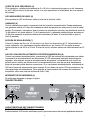
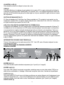
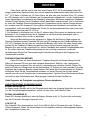
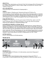
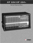
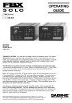
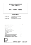
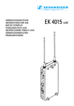
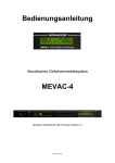
EQ 31 FX
™
3 1 B an d Pro fes s i o n a l G ra p h i c Eq ua l i ze r
Owner’s Manual
Intended to alert the user to the presence of uninsulated “dangerous voltage” within the product’s
enclosure that may be of sufficient magnitude to constitute a risk of electric shock to persons.
Intended to alert the user of the presence of important operating and maintenance (servicing)
instructions in the literature accompanying the product.
CAUTION: Risk of electrical shock — DO NOT OPEN!
CAUTION: To reduce the risk of electric shock, do not remove cover. No user serviceable parts inside. Refer
servicing to qualified service personnel.
WARNING: To prevent electrical shock or fire hazard, do not expose this appliance to rain or moisture. Before
using this appliance, read the operating guide for further warnings.
Este símbolo tiene el propósito, de alertar al usuario de la presencia de “(voltaje) peligroso” que no tiene
aislamiento dentro de la caja del producto que puede tener una magnitud suficiente como para constituir
riesgo de corrientazo.
Este símbolo tiene el propósito de alertar al usario de la presencia de instruccones importantes sobre la
operación y mantenimiento en la literatura que viene con el producto.
PRECAUCION: Riesgo de corrientazo — No abra.
PRECAUCION: Para disminuír el riesgo de corrientazo, no abra la cubierta. No hay piezas adentro que el usario
pueda reparar. Deje todo mantenimiento a los técnicos calificados.
ADVERTENCIA: Para evitar corrientazos o peligro de incendio, no deje expuesto a la lluvia o humedad este
aparato Antes de usar este aparato, Iea más advertencias en la guía de operación.
Ce symbole est utilisé pur indiquer à l’utilisateur la présence à l’intérieur de ce produit de tension nonisolée dangereuse pouvant être d’intensité suffisante pour constituer un risque de choc électrique.
Ce symbole est utilisé pour indiquer à l’utilisateur qu’il ou qu’elle trouvera d’importantes instructions sur
l’utilisation et l’entretien (service) de l’appareil dans la littérature accompagnant le produit.
ATTENTION: Risques de choc électrique — NE PAS OUVRIR!
ATTENTION: Afin de réduire le risque de choc électrique, ne pas enlever le couvercle. Il ne se trouve à l’intérieur
aucune pièce pouvant être reparée par l’utilisateur. Confier I’entretien à un personnel qualifié.
AVERTISSEMENT: Afin de prévenir les risques de décharge électrique ou de feu, n’exposez pas cet appareil à la
pluie ou à l’humidité. Avant d’utiliser cet appareil, lisez les avertissements supplémentaires situés dans le guide.
Dieses Symbol soll den Anwender vor unisolierten gefährlichen Spannungen innerhalb des Gehäuses
warnen, die von Ausreichender Stärke sind, um einen elektrischen Schlag verursachen zu können.
Dieses Symbol soll den Benutzer auf wichtige Instruktionen in der Bedienungsanleitung aufmerksam
machen, die Handhabung und Wartung des Produkts betreffen.
VORSICHT: Risiko — Elektrischer Schlag! Nicht öffnen!
VORSICHT: Um das Risiko eines elektrischen Schlages zu vermeiden, nicht die Abdeckung enfernen. Es befinden
sich keine Teile darin, die vom Anwender repariert werden könnten. Reparaturen nur von qualifiziertem
Fachpersonal durchführen lassen.
ACHTUNG: Um einen elektrischen Schlag oder Feuergefahr zu vermeiden, sollte dieses Gerät nicht dem Regen
oder Feuchtigkeit ausgesetzt werden. Vor Inbetriebnahme unbedingt die Bedienungsanleitung lesen.
2
ENGLISH
Congratulations on purchasing the EQ™ 31FX! With its introduction, Peavey engineers have
taken graphic equalizers to the next level. The EQ™ 31FX offers 31 bands of 1/3 octave filters
featuring superior constant “Q” devices. LED indicators are located in the slider of the frequency
bands to identify the presence of a high energy signal (usually feedback). This sophisticated feedback detector system will allow you to quickly identify and remove feedback. It works like this: When
the feedback detection circuit detects the frequency band with the most energy, it causes the LED in
the slider of the associated frequency band to illuminate. By moving the fader downward for that
band, the likelihood of feedback is reduced/eliminated. Most use the EQ 31FX in one of two ways:
1. To catch and reduce/eliminate feedback “on-the-fly” during a performance. 2. To determine
frequency bands that are susceptible to feedback BEFORE the performance, and eliminating them
in advance.
After the system is set up, bring up the microphone levels slowly. As they start to feed back,
note the LED activity on the EQ 31FX feedback bands. Move the faders to decrease the “identified”
bands. Now you have eliminated a high percentage of potential feedback problems, before the performance even begins! Note: It is not uncommon for feedback to be active over several frequency
bands. Also, go easy when making fader adjustments since extreme movements will affect your performance and be counterproductive.
OPERATION NOTE
This equalizer is designed to provide room equalization, feedback control and system tone
control. No amount of equalization will correct an acoustically bad room/mic/speaker arrangement or
completely correct the response of a poor loudspeaker. Always begin with all sliders in the “0”
position and avoid excessively cutting large segments of the audio passband, which would limit the
system’s dynamic range. Exercise caution when attempting to boost equalization below cut-off of the
speaker system. Typical sound reinforcement enclosures are not designed for 20 Hz performance
and transducer damage could result.
FRONT PANEL
4
1
2
5
7
6
8
9
3
FRONT PANEL FEATURES:
BYPASS SWITCH (1)
In Bypass mode (switch in), the input signal is routed directly to the output and is unaffected by all
front panel controls except the low and high cut filters.
BYPASS LED (2)
This LED will illuminate when the Bypass switch is in the “in” position, indicating that the EQ and
3
gain controls are bypassed.
LOW CUT (3)
A high pass filter, continuously variable from 5 Hz to 200 Hz. Low frequency roll-off is at 12 dB per
octave. Adjust this control to approximate low frequency cut-off of speaker system.
HIGH CUT (4)
A low pass filter, continuously variable from 5 kHz to 35 kHz. High frequency roll-off is at 12 dB per
octave. Adjust this control slightly above high frequency system limitation.
LED LEVEL METER (5)
This multicolored LED ladder indicates output level.
GAIN (6)
Calibrated control for regulating overall gain of the equalizer section. Unity gain throughout the
signal chain may be maintained by recovering lost signal at this point. Example: Assume the
equalization process has introduced a signal loss of -6 dB by negative (-) adjustment of the EQ
section. The gain should then be adjusted to +6 to maintain unity gain through the equalizer.
EQUALIZER SECTION (7)
31 bands of 1/3 octave filters. The filters are constant “Q” devices, located at ISO center
frequencies. Effective equalization range is from 20 Hz to 20 kHz. Maximum cut or boost per
frequency is 15 dB.
AUTOMATIC FEEDBACK LOCATING LEDs (8)
When feedback occurs, the LED of the frequency band that is feeding back will illuminate indicating
feedback in that band. The LED will remain illuminated for a few seconds even after the feedback is
gone. This is to allow you to see where the feedback is if the feedback goes away before any
correction is made. If there is no feedback occurring, the LED of the frequency band with the most
energy in it will illuminate. Just because the LED is illuminated does not mean that there is feedback
occurring. For best performance of the automatic feedback locating system, use an input signal of
0 dB (1V RMS).
POWER SWITCH (9)
REAR PANEL
5
4
Used to turn AC mains power on or off.
INPUT XLR (1)
4
3
2
1
A three-pin female XLR jack is provided for electronically balanced input termination (pin 2
positive, pin 3 negative).
INPUT 1/4" (2)
1/4" tip-ring-sleeve (stereo) jack provides balanced input when used with stereo (TRS) 1/4" plugs
and 2-conductor shielded cables. When used with a mono 1/4" phone plug, the input is unbalanced.
OUTPUT XLR (3)
A transformer balanced, male XLR output provides line-balancing to other pieces of audio
equipment (power amps, etc.) Balanced output is recommended for rejection of hum, noise and
outside interference (pin 2 positive, pin 3 negative).
OUTPUT 1/4" (4)
1/4" phone jack is provided for unbalanced output termination.
LINE CORD (120V Products only) (5)
We have incorporated a 2-wire line (mains) cable for power on the EQ 31FX.
Power requirements:
Domestic: 120VAC / 60 Hz / 20 W.
Export: 230VAC / 50/60 Hz / 20 W.
NOTE: CAUTION: TO PREVENT ELECTRIC SHOCK, MATCH WIDE BLADE OF PLUG TO WIDE SLOT,
EQ 31FX Application:
™
Mono send from Mixer to external
EQ/Power Amp combination.
Main Balanced Output
EQ 31FX
Balanced Input
EQ 31FX Balanced Output
Parallel Patch
Balanced Input CH 2
CS800S Balanced Input CH 1
Power Amp
Out CH 2
Power Amp
Out CH 1
5
SPECIFICATIONS
Frequency Response:
+/- 1 dB 20 Hz to 20 kHz
4.77
Maximum Boost and Cut Filter:
+/- 15 dB
Distortion:
.005% 20 Hz-20 kHz
Maximum Boost and Cut Gain (WideBand
Gain):
+/- 15 dB
Input Impedance:
Balanced 20 k Ohms (Equal impedance to
ground)
Low Cut Filter:
12 dB Per Octave
Output Impedance:
330 Ohms
Maximum Input Level:
+21 dBu (8.6 V RMS)
Frequency:
Min: 5 Hz
Max: 200 Hz
Maximum Output Level:
+27 dBu (17 V RMS)
High Cut Filter:
12 dB Per Octave
Nominal Input Level:
0 dBV (1 V RMS)
Frequency:
Min: 5 kHz
Max: 35 kHz
Nominal Output Level:
0 dBV (1 V RMS)
All specifications are typical unless otherwise
noted. 0 dBV=1 Volt. All specifications are
referenced to nominal output level (0 dBV)
unless otherwise stated. All measurements are
wideband 20 Hz to 20 kHz unless otherwise
stated. NOTE: All specs measured at 1V RMS
input and unbalanced output. All sliders at
mid position, all switches out unless otherwise
noted. Due to our efforts for constant
improvement, features and specifications
listed herein are subject to change without
notice.
Input Headroom:
Nominal 21 dBu
Output Headroom:
27 dBu
Output Noise:
EQ in bypass: -101 dBV
EQ in, all flat: -95 dBV
Filter Frequencies:
20, 25, 32, 40, 50, 63, 80, 100, 125, 160,
200, 250, 315, 400, 500, 630, 800, 1 k,
1.25 k, 1.6 k, 2 k, 2.5 k, 3.15 k, 4 k, 5 k,
6.3 k, 8 k, 10 k, 12.5 k, 16 k, and 20 kHz
Filter Q:
6
ESPAÑOL
¡Lo felicitamos por adquirir el ecualizador EQ™ 31 FX! Con la presentación de este equipo,
los ingenieros de Peavey han creado una nueva generación de ecualizadores gráficos. El ecualizador EQ™ 31 FX ofrece 31 bandas de filtros de 1/3 de octava con dispositivos de “Q” (selectividad)
constante de calidad superior. Los LED indicadores se encuentran en el control deslizante de las
bandas de frecuencia para identificar la presencia de señales de alta energía (normalmente, son
señales de retroalimentación). Este sofisticado sistema detector le permitirá identificar y eliminar
rápidamente la retroalimentación. Funciona de la siguiente manera: Cuando el sistema de detección
de retroalimentación identifica la banda de frecuencia de mayor energía, se enciende el LED del
control deslizante de la banda de frecuencia correspondiente. Esto permite reducir o eliminar la
probabilidad de retroalimentación desplazando el atenuador de esa banda. La mayoría de los usuarios utilizan el ecualizador EQ 31FX de dos maneras: 1. Para captar y reducir/eliminar “al instante” la
retroalimentación en un sistema de amplificadores. 2. Para determinar las bandas de frecuencia
susceptibles de retroalimentación ANTES de utilizar el sistema de amplificadores, a fin de eliminarlas anticipadamente.
Después de configurar el sistema, aumente lentamente los niveles de micrófono. Cuando
comience la retroalimentación, observe la actividad de los LED indicadores de las bandas de frecuencia del ecualizador EQ 31 FX. Desplace los atenuadores para reducir las bandas “identificadas”. De esta forma usted puede eliminar un alto porcentaje de problemas potenciales de retroalimentación, ¡antes de utilizar el sistema de amplificadores! Nota: Es común que la retroalimentación
ocurra simultáneamente en varias bandas de frecuencia. Proceda lentamente al ajustar los atenuadores, pues los movimientos rápidos afectan la calidad de la reproducción y resultan contraproducentes.
NOTA SOBRE LA OPERACIÓN
El ecualizador está diseñado para proporcionar ecualización ambiental y controles de retroalimentación y tono en sistemas de amplificadores. Ninguna ecualización puede compensar una combinación o distribución acústicamente deficiente de sala, micrófonos y altavoces, como tampoco corregir completamente la respuesta de un altavoz deficiente. Comience siempre con los controles
deslizantes en la posición “0” y evite anular excesivamente segmentos largos de la banda pasante
de audio, porque se limitaría la gama dinámica del sistema. Sea cuidadoso cuando intente reforzar
la ecualización por debajo de la frecuencia de corte de los altavoces. Las cajas acústicas de refuerzo de sonido típicas no están diseñadas para funcionar a 20 Hz y podrían dañarse los transductores.
Consulte los diagramas del panel delantero en la sección de inglés de este manual.
CARACTERÍSTICAS DEL TABLERO FRONTAL
INTERRUPTOR DE DERIVACIÓN (1)
En el modo de derivación o desvío (interruptor hacia adentro), la señal de entrada se dirige directamente a la salida y no es afectada por los controles del panel frontal, excepto los filtros de corte de
frecuencias bajas y altas.
LED DE DERIVACIÓN (2)
Este LED se enciende cuando el interruptor de derivación está hacia adentro, para indicar que se
puentean los controles de ecualización y ganancia.
CORTE DE BAJA FRECUENCIA (3)
Filtro pasaaltos, variable continuamente de 5 Hz a 200 Hz. La atenuación progresiva a baja frecuencia es de 12 dB por octava. Ajuste este control a un valor aproximado a la frecuencia de corte inferior del sistema de altavoces.
7
CORTE DE ALTA FRECUENCIA (4)
Filtro pasabajos, variable continuamente de 5 a 35 kHz. La atenuación progresiva a alta frecuencia
es de 12 dB por octava. Ajuste este control a un valor aproximado a la frecuencia de corte superior
del sistema.
LED INDICADORES DE NIVEL (5)
Esta escalera de LED multicolores indica el nivel de la señal de salida.
GANANCIA (6)
Control calibrado para regular la ganancia total de la sección de ecualización. Puede mantenerse
una ganancia unitaria a lo largo de la cadena de señal recuperando en este punto el nivel de señal
perdido. Por ejemplo, supongamos que el proceso de ecualización introdujo una pérdida de señal de
–6 dB debido a un ajuste negativo (–) de la ecualización. La ganancia puede ajustarse entonces en
+6 dB para mantener la ganancia unitaria del ecualizador (es decir, el nivel de salida es igual al
nivel de entrada).
SECCIÓN DE ECUALIZACIÓN (7)
Ofrece 31 bandas de filtros de 1/3 de octava. Los filtros son dispositivos de “Q” (selectividad) constante, calibrados a las frecuencias centrales definidas por las normas ISO. La gama de ecualización efectiva es de 20 Hz a 20 kHz. El nivel de corte y refuerzo máximo de cada frecuencia es 15
dB.
LED DE LOCALIZACIÓN AUTOMÁTICA DE RETROALIMENTACIÓN (8)
Cuando se produce retroalimentación, se enciende el LED de la banda retroalimentada para indicar
la presencia de retroalimentación en dicha banda. El LED permanece iluminado durante algunos
segundos, aún después de que la retroalimentación desaparece. La finalidad de esta función es
permitir que el usuario vea dónde ocurrió la retroalimentación en caso de que ésta desaparezca
antes de que sea posible efectuar correcciones. Si no se produce retroalimentación, se enciende el
LED de la banda de frecuencia de mayor energía. El solo hecho de que el LED se encienda no significa que exista retroalimentación. Para optimizar el funcionamiento del sistema de localización
automática, utiliza una señal de entrada de 0 dB (1 Vef).
INTERRUPTOR DE ENCENDIDO (9)
Se utiliza para encender y apagar el equipo.
TABLERO TRASERO
5
4
3
2
1
CARACTERÍSTICAS DEL TABLERO TRASERO
ENCHUFE XLR DE ENTRADA (1)
Enchufe hembra XLR de tres terminales provisto para terminación de entrada equilibrada electróni8
camente (terminal 2 positivo, terminal 3 negativo).
ENTRADA DE 1/4 PULG. (2)
Enchufe hembra de tipo de punta, anillo y manguito de 1/4 pulg. (estereofónico) que proporciona
una entrada equilibrada cuando se usa con enchufes estereofónicos de 1/4 pulg. (TRS) y cables
blindados de dos conductores. Cuando se usa con un enchufe fonográfico monofónico de 1/4 pulg.,
la entrada no es equilibrada.
ENCHUFE XLR DE SALIDA (3)
Salida XLR macho equilibrada por transformador que proporciona balance de línea para otros equipos de audio (amplificadores de potencia, etc.). La salida equilibrada se recomienda para el rechazo
de zumbido, ruido e interferencia externa (terminal 2 positivo, terminal 3 negativo).
SALIDA DE 1/4 PULG. (4)
Enchufe hembra de 1/4 pulg. para terminación de salida no equilibrada.
CORDÓN DE ALIMENTACIÓN (productos para 120 V únicamente) (5)
Hemos incorporado un cable bifilar para la alimentación eléctrica del ecualizador EQ 31FX.
Requisitos de energía eléctrica:
Estados Unidos: 120 VCA, 60 Hz, 20 W
Otros países: 230 VCA, 50 ó 60 Hz, 20 W
PRECAUCIÓN: PARA EVITAR DESCARGAS ELÉCTRICAS, HAGA COINCIDIR EL
TERMINAL ANCHO DEL ENCHUFE CON LA RANURA ANCHA E INSERTE EL ENCHUFE
9
XR™ 31FX ESPECIFICACIONES
COMPLETAMENTE.
Respuesta de frecuencia:
±1 dB de 20 Hz a 20 kHz
20 kHz.
Q (selectividad) de filtros:
4,77
Distorsión:
0,005% de 20 Hz a 20 kHz
Filtros de refuerzo y corte (niveles máximos):
±15 dB
Impedancia de entrada:
20 kΩ, equilibrada (igual impedancia con
respecto a tierra)
Ganancias de refuerzo y corte máximas
(ganancia de banda ancha):
±15 dB
Impedancia de salida:
330 Ω
Filtros de corte de baja frecuencia:
12 dB por octava
Máximo nivel de entrada:
+21 dBu (8,6 Vef)
Frecuencias:
Mínima: 5 Hz
Máxima: 200 Hz
Máximo nivel de salida:
+27 dBu (17 Vef)
Filtros de corte de alta frecuencia:
12 dB por octava
Nivel de entrada nominal:
0 dBV (1 Vef)
Frecuencias:
Mínima: 5 kHz
Máxima: 35 kHz
Nivel de salida nominal:
0 dBV (1 Vef)
A menos que se especifique lo contrario, todas
las especificaciones corresponden a valores típicos; se considera que 0 dBV = 1 V; todas las
especificaciones están referidas al nivel de salida nominal (0 dBV); todas las mediciones corresponden a una banda ancha de 20 Hz a 20 kHz.
NOTA: A menos que se especifique lo contrario,
todas las especificaciones corresponden a un
nivel de entrada de 1 Vef, con salida no equilibrada, con todos los controles deslizantes en la
posición central y todos los interruptores hacia
afuera. Debido a nuestros constantes esfuerzos
por mejorar los sistemas, las características y
las especificaciones indicadas en este folleto
están sujetas a cambios sin previo aviso.
Tolerancia de máximo nivel de señal de
entrada:
Nominal 21 dBm
Tolerancia de máximo nivel de señal de
salida:
27 dBu
Ruido de salida:
Ecualización en modo de derivación: –101 dBV
Ecualización plana (sin corrección de niveles):
–95 dBV
Frecuencias de filtros:
20; 25; 32; 40; 50; 63; 80; 100; 125; 160; 200;
250; 315; 400; 500; 630; 800; 1 kHz; 1,25 kHz;
1,6 kHz; 2 kHz; 2,5 kHz; 3,15 kHz; 4 kHz; 5 kHz;
6,3 kHz; 8 kHz; 10 kHz; 12,5 kHz; 16 kHz y
10
FRANÇAIS
Nous vous félicitons pour l’achat de cet EQ™ 31FX! L’EQ™ 31FX dispose de 31 filtres 1/3
d’octave de qualité supérieure, à “Q” constant. Des LEDs situées sur les curseurs des potentiomètres rectilignes permettent de repérer la présence d’un signal haute énergie sur la bande de
fréquences concernée (généralement indiquant un feedback). Ce détecteur de feedback vous permettra de rapidement identifier et éliminer tout larsen. Lorsque le système détecte la bande de
fréquence ayant la plus haute énergie, la LED du slider qui lui correspond s’illumine. En déplaçant
son curseur vers la bas, la possibilité de feedback est diminuée/éliminée. Le EQ 31FX peut être utilisé de deux manières différentes: 1. Pour repérer et diminuer/éliminer le larsen en temps réél pendant une performance. 2. Pour déterminer avant la performance quelles bandes de fréquences
sont susceptibles d’entrer en feedback et éliminer le problème à l’avance.
Une fois le système de sonorisation installé, montez progressivement les niveaux des micros.
Lorsqu’un larsen apparaît, repérez l’activation des LED sur les bandes du EQ 31FX. Déplacez les
curseurs pour diminuer le gain des bandes identifiées. Vous éliminez ainsi un grand pourcentage
des problèmes de larsen potentiels avant même que ne commence le show. Note: Il n’est pas rare
qu’un larsen apparaisse sur différentes bandes de fréquences en même temps. En conséquence,
évitez les réglages excessifs de vos faders qui pourraient nuire à votre performance et être anti-productifs.
conseil d’utilisation
Cette unité est conçue pour équaliser une pièce, contrôler le feedback est ajuster la tonalité
d’un système. Aucune équalisation ne corrigera un mauvais arrangement ou une mauvaise disposition des divers éléments acoustiques (micros, enceintes et salle), ni la réponse d'un haut-parleur
déficient. Avant de procéder, placez toujours les sliders de votre équaliseur en position médiane.
Evitez de couper de trop grandes plages de fréquences afin de ne pas limiter la dynamique du système. Prenez de grandes précautions lorsque vous équalisez en dessous des fréquences de coupures de votre système de sonorisation. La plupart des enceintes ne sont pas conçues pour travailler à 20Hz et les risques d'endommager vos H.P.s sont grands.
Veuillez-vous référer au “front panel art” situé dans la section en langue anglaise de
ce manual.
CARACTÉRISTIQUES DU PANNEAU AVANT
sélecteur BYPASS (1)
En mode Bypass (sélecteur engagé), le signal d’entrée est dirigé directement vers la sortie et n’est
pas affecté par les contrôles de façade exceptés les filtres low et high cut.
LED de BYPASS (2)
Cette LED s’illuminera lorsque le sélecteur Bypass sera engagé, indiquant que l’EQ et le contrôle de
gain ne sont pas effectifs.
FILTRE LOW CUT (3)
Filtre passe-haut de fréquence de coupure variable de 5 Hz à 200 Hz. Sa pente est de 12 dB par
octave. Ajustez ce contrôle à la valeur approximative de la fréquence de coupure basse du système
d’enceinte.
FILTRE HIGH CUT (4)
Filtre passe-bas de fréquence de coupure variable de 5 kHz à 35 kHz. Sa pente est de 12 dB par
octave. Réglez ce contrôle légèrement au dessus de la fréquence de coupure haute du système
d’enceinte.
11
VU METRE A LED (5)
Cette échelle multicolore indique le niveau de sortie.
GAIN (6)
Contrôle calibré pour le réglage du gain général de la section EQ. Le gain unitaire de la chaîne de
traitement du signal peut être rétabli grâce à ce contrôle. Ainsi, si le réglage d’égalisation induit une
perte de -6 dB le contrôle de gain pourra être réglé sur +6 pour maintenir un gain unitaire au travers
de l’équaliseur.
SECTION d’EQUALIsation (7)
31 filtres de bandes de 1/3 d’octave. Les filtres possèdent un “Q” constant et sont centrés sur les
fréquences standard ISO. Le registre effectif d’équalisation s’étend de 20 Hz à 20 kHz. L’atténuation
et le gain maximum par bande sont de 15 dB.
LEDs de localisation automatique du FEEDBACK (8)
A l'apparition du feedback, la LED correspondant à la bande de fréquence concernée s'illumine. Si
le feedback est fort et intermittent, la LED restera allumée quelques secondes aprés sa disparition,
vous permettant de repérer la bande de fréquence fautive et d'ajuster votre équaliseur. Cela vous
permet de voir où se situe le feedback s'il disparaît avant qu'une correction n'ait pu être effectuée.
S'il n'y a pas de feedback, la LED correspondant à la bande de fréquence présentant la plus haute
énergie s'illuminera. Une LED allumée ne signifie pas obligatoirement la présence d'un feedback.
Pour une performance optimum du système de localisation du feedback, utilisez un signal d’entrée à
0 dB (1V RMS).
INTERRUPTEUR DE MISE SOUS TENSION (9)
Pressez l'interrupteur pour le mettre en position “ON”. Une LED verte s'illumine indiquant la mise
sous tension de l'unité.
CARACTÉRISTIQUES DU PANNEAU ARRIÉRE:
PANNEAU ARRIÉRE
5
4
3
2
1
entrée XLR (1)
Prise XLR femelle symétrisée électroniquement (pin 2 positif, pin 3 negatif).
entrée jack (2)
Prise Jack TRS (stéréo) fournissant une entrée symétrique avec un prise Jack stéréo (TRS) et un
câble à deux conducteurs + blindage. Utilisé avec une prise Jack mono, l’entrée est asymétrique.
sortie XLR (3)
Une sortie mâle XLR fournit une sortie ligne symétrique aux autres éléments de l’équippement sono
(amplis de puissance, etc...) Les sorties symétriques sont recommandées pour une réjection maximum des souffles, bruits de fond et autres interférences extérieures (pin 2 positif, pin 3 negatif).
sortie jack (4)
12
Prise Jack pour sortie asymétrique.
Alimentation nécessaire:
230VAC / 50/60 Hz / 20 W.
XR™ 31FX SPECIFICATIONS
Réponse fréquentielle:
+/- 1 dB 20 Hz to 20 kHz
Facteur Q des filtres:
4.77
Distorsion:
.005% 20 Hz-20 kHz
Boost et Cut maximum des filtres:
+/- 15 dB
Impédance d’entrée:
Symétrique: 20 k Ohms (Impédance à la masse
équivalente)
Boost et Cut maximum du Gain général:
+/- 15 dB
Filtre coupe-bas:
12 dB Par Octave
Impédance de sortie:
330 Ohms
Niveau maximum d'entrée:
+21 dBu (8.6 V RMS)
Fréquence:
Min: 5 Hz
Max: 200 Hz
Niveau de sortie maximum:
+27 dBu (17 V RMS)
Filtre coupe-haut:
12 dB Per Octave
Niveau d'entrée nominal:
0 dBV (1 V RMS)
Fréquence:
Min: 5 kHz
Max: 35 kHz
Niveau de sortie nominal:
0 dBV (1 V RMS)
Toutes les caractéristiques sont typiques sauf
indications. 0 dBV=1 Volt. Toutes les caractéristiques sont données pour un niveau de sortie
nominal (0 dBV) sauf indications. Toutes les
mesures s’appliquent pour la bande passante de
20 Hz à 20 kHz sauf indications.
NOTE: Caractéristiques mesurées à 1V RMS à
l’entrée asymétrique. Tous les curseurs en position médiane et sélecteurs désengagés sauf indications. Etant donnés nos efforts constants pour
l’amélioration de notre matériel,les caractéristiques et spécifications listée ici peuvent être
modifiées sans préavis.
Headroom en entrée:
21 dBu Nominal
Headroom en sortie:
27 dBu
Bruit en sortie:
EQ en bypass: -101 dBV
EQ engagé, tout à 0: -95 dBV
Fréquences des filtres:
20, 25, 32, 40, 50, 63, 80, 100, 125, 160,
200, 250, 315, 400, 500, 630, 800, 1 k,
1.25 k, 1.6 k, 2 k, 2.5 k, 3.15 k, 4 k, 5 k,
6.3 k, 8 k, 10 k, 12.5 k, 16 k, et 20 kHz
13
DEUTSCH
Vielen Dank, daß Sie sich für den Kauf eines Peavey EQ™ 31FX entschieden haben. Mit
diesem graphischen Equalizer haben sich unsere Ingenieure wieder einmal selbst übertroffen. Der
EQ™ 31FX bietet 31 Bänder von 1/3 Oktav-Filtern, die eine sehr gute konstante Güte (“Q”) aufweisen. LED Anzeigen sind in den Schiebern der Frequenzbänder untergebracht, um das Auftreten eines
hohen Signalpegels (normalerweise ein Feedback) anzuzeigen. Mit diesem eingebauten FeedbackDetektor-System können Sie ein Feedback schnell identifizieren und eliminieren. Und so funktioniert
es: wenn die Feedback Erkennungsschaltung das Frequenzband mit der meisten Energie erkannt
hat, leuchtet eine LED-Anzeige auf. Das mögliche Auftreten eines Feedbacks wird reduziert oder
ausgeschaltet, wenn man den Schieberegler (Fader) für das entsprechende Band nach unten zieht.
Viele Bediener benutzen den EQ 31FX so:
1. Ein Feedback zu lokalisieren und “on the-fly” während einer Performance zu reduzieren oder zu
beseitigen 2. Um Frequenzbänder die für Feedback vor der Performance empfänglich sind zu
bestimmen und diese schon vorher zu beseitigen.
Wenn das Beschallungssystem aufgestellt ist, heben Sie die Mikrofon-Pegel langsam an.
Wenn ein Feedback entsteht, beachten Sie bitte die LED-Anzeigen an den Feedbackbändern des
EQ 31FX. Schieben Sie die Fader der “identifizierten Bänder” nach unten. Sie haben hiermit einen
großen Teil des Feedback-Problems ausgeräumt, bevor die Performance begonnen hat. Bitte
beachten Sie, dass es nicht ungwöhnlich ist, daß ein Feedback über mehrere Frequenzbänder aktiv
ist. Sie sollten daher die Fadereinstellung langsam und vorsichtig vornehmen, vorschnelle
Veränderungen können Ihre Performance negativ beeinflussen und genau das Gegenteil vom
Gewünschten erreichen.
ZUR BEACHTUNG BEI BETRIEB
Dieser EQ dient zur Raum-Equalisation, Feedback-Kontrolle und System-Klang-Kontrolle.
Selbst mit extremen EQ kann man eine schlechte Raumakustik, Mikrofon- oder LautsprecherEinstellung kaum korrigieren. Dies gilt auch für Lautsprecher von schlechter Qualität. Stellen Sie
daher die Fader am Anfang immer auf die Mittelstellung (“0”-Position) ein und vermeiden Sie große
Segmente des Audiopass-Bandes zubeschneiden. Dies würde den Aussteuerbereich des Systems
minimieren. Wenn Sie die Frequenzbänder anheben, so lassen Sie auch hier Vorsicht walten,
speziell unter der cut-off-Frequenz des Lautsprechersystems. Typische Sound Reinforcement-Boxen
sind nicht für eine Performance unter 20Hz geeignet, hierdurch können Schäden am
Siehe Diagramm der Frontplatte im englischen Teil des Handbuchs.
CARACTERISTIQUES DU PANNEAU AVANT.
BYPASS SCHALTER (1)
Im Bypass mode (Schalter ein) ist das Eingangssignal direkt zum Ausgang überbrückt und wird nicht
von den Frontplattenreglern beeinflusst, ausser von den Hoch- und Tiefpass-Filtern.
BYPASS LEDANZEIGE (2)
Diese LED-Anzeige leuchtet auf, wenn der Bypass-Schalter in der “In” Position steht und anzeigt,
das der EQ und der Gainregler “bypassed” sind.
LOW CUT (3)
Ein Hochpass-Filter, durchstimmbar von 5 Hz bis 200 Hz. Roll-off-Charakeristik ist bei 12 dB pro
Oktave festgesetzt. Stellen Sie diesen Regler auf die ungefähre unterste zuübertragende Frequenz
des Lautsprecher-Systems ein.
14
HIGH CUT (4)
Ein Tiefpass-Filter, durchstimmbar von 5 kHz bis 35 kHz. Die Hochfrequenz Roll-off-Charakteristik ist
bei 12 dB pro Oktave festgesetzt. Stellen Sie diesen Regler ein wenig über der höchsten zuübertragenden Frequenz ein.
LED LEVEL METER (5)
Diese mehrfarbige LED-Anzeige zeigt den Ausgangspegel an. .
GAIN (6)
Kalibrierter Regler zur Regulierung der Gesammtverstärkung der EQ-Sektion. Der
Verstärkungsfaktor durch die Signalkette sollte an diesem Punkt ausgepegelt werden, um eventuell
verlorene Signalpegel wieder herzustellen. Beispiel: stellen Sie sich vor, der EQ-Prozess zeigt einen
Signalverlust von -6 dB von den negativ (-) Einstellungen der EQ-Sektion an. Der Gain sollte dann
auf +6 eingestellt werden, um den Verstärkungsfaktor durch den EQ wiederherzustellen.
EQUALIZER SEKTION (7)
31 Bänder von 1/3 Oktav-Filtern. Die Filter sind konstante “Q”(Güte) Filter, welche um die ISO
Center Frequenzen fixiert sind. Effektive EQ-Range ist von 20 Hz bis 20 kHz.Die maximale
Absenkung oder Anhebung pro Frequenzband beträgt 15 dB.
AUTOMATISCHE FEEDBACK LOCATING LEDs (8)
Wenn ein Feedback auftritt, leuchtet die Anzeige des Frequenzbandes auf, indessen Bereich das
Feedback sich aufgebaut hat. Die LED-Anzeige leuchtet auch dann noch eine Weile auf, wenn das
Feedback längst beseitigt ist. Dies macht es Ihnen möglich zu sehen wo sich das Feedback befand
oder wo es auftrat, bevor Sie irgendwelche Korrekturen vornehmen könnten. Wenn kein Feedback
auftritt, leuchtet die LED des Frequenzbandes auf, in der sich höchste Energie befindet, was jedoch
nicht bedeutet, das es sich hier um ein Feedback handelt. Für beste Resultate des automatischen
Feedback Locating System benutzen Sie bitte ein Eingangssignal von 0 dB (1V RMS).
NETZSCHALTER (9)
Zum An- und Ausschalten des Betriebsspannung.
RÜCKPLATTE
5
4
3
2
1
EINGANG XLR (1)
3-Pin Female (weiblich) XLR-Buchse ist für elektronischen symmetrischen Eingang.(pin 2
positiv, pin 3 negativ).
EINGANG 1/4" (2)
1/4" Tip-Ring-Sleeve, Stereoklinkenbuchse bietet symmetrierten Eingang.für (TRS) 1/4"
Klinkenstecker mit zweiartrig abgeschirmten Kabel. Bei Betrieb mit einem Monostecker wird der
15
Eingang automatisch unsymmetrisch geschaltet.
AUSGANG XLR (3)
Ein Trafosymmetrischer Male (männlicher) XLR Ausgang führt das Signal zu weiteren Audiogeräten
wie Leistungsverstärker etc..
Symmetrische Ausgänge werden zur Reduzierung von Nebengeräuchen wie brummen und
rauschen, sowie anderen äusseren Einflüssen empfohlen. (Pin 2 positiv, Pin 3 negativ).
AUSGANG 1/4" (4)
1/4" Klinkenbuchse für unsymmetrischen Ausgangspegel.
NETZANSCHLUSSKABEL (5)
Wir haben ein dreiartriges Kabel für den Netzanschlu´ß des EQ 31FX beigefügt.
Spannungsversorgung:
230VAC / 50/60 Hz / 20 W.
NOTE: Um einen elektrischen Stromschlag zuvermeiden, achten Sie bitte darauf, daß alle Teile
16
EQ™ 31FX SPEZIFIKATIONEN
Frequenzgang:
+/- 1 dB 20 Hz to 20 kHz
Filter Güte (Q)
4.77
Verzerrung:
.005% 20 Hz-20 kHz
Maximaler Boost und Cut Filter:
+/- 15 dB
Eingangs-Impedanz:
Balanced 20 k Ohms (Equal impedance to
ground)
Maximaler Boost und Cut Gain (BreitbandGain):
+/- 15 dB
Ausgangs-Impedanz:
330 Ohms
Tiefpassfilter:
12 dB Pro Octave
Maximaler Eingangs-Pegel:
+21 dBu (8.6 V RMS)
Frequenz:
Min: 5 Hz
Max: 200 Hz
Maximaler Ausgangs-Pegel:
+27 dBu (17 V RMS)
Hochpassfilter:
12 dB Per Octave
Nominaer Eingangs-Pegel:
0 dBV (1 V RMS)
Frequenz:
Min: 5 kHz
Max: 35 kHz
Nominaler Ausgangs-Pegel:
0 dBV (1 V RMS)
Alle Spezifikationen sind typisch, außer wenn sie
anderes erläutert sind. 0 dBV=1 Volt. Alle
Spezifikationen sind auf den nominalen
Ausgangspegel bezogen.(0 dBV) außer anders
erläutert. Alle Messungen von 20 Hz bis 20 kHz
außer anders erläutert.
Eingangs-Aussteuerung:
Nominal 21 dBu
Ausgangs-Aussteuerung:
27 dBu
Ausgangs-Geräusch:
EQ in bypass: -101 dBV
EQ in, all flat: -95 dBV
Bemerkung: Alle Spezifikationen sind an 1V
RMS Eingang und unsymmetrischen Ausgang
gemessen. Alle Schieber in Mittelposition, alle
Schalter aus, außer anders erläutert. Aufgrund
ständiger Weiterentwicklungen und
Verbesserungen können äußerliche
Veränderungen und Spezifikationen an unseren
Produkten ohne Vorankündigung vorgenommen
werden.
Filterfrequenzen:
20, 25, 32, 40, 50, 63, 80, 100, 125, 160,
200, 250, 315, 400, 500, 630, 800, 1 k,
1.25 k, 1.6 k, 2 k, 2.5 k, 3.15 k, 4 k, 5 k,
6.3 k, 8 k, 10 k, 12.5 k, 16 k, and 20 kHz
17
THIS LIMITED WARRANTY VALID ONLY WHEN PURCHASED AND REGISTERED IN THE UNITED STATES OR CANADA. ALL EXPORTED PRODUCTS ARE SUBJECT TO
WARRANTY AND SERVICES TO BE SPECIFIED AND PROVIDED BY THE AUTHORIZED DISTRIBUTOR FOR EACH COUNTRY.
Ces clauses de garantie ne vent vaiables qu’aux Etats-Unis et au Canada. Dans tour les autres pays, les clauses de garantie et de maintenance vent fixees par le distributeur
national et assuree par lul scion la legislation envigueur. • • Diese Garantie ist nur in den USA and Kanada gultig. Alle ExportProdukte sind der Garantie und dem Service
des Importeurs des jewelligen Landes unterworfen. • • Esta garantia es valida solamente cuando et producto es comprado en E.U. continentales o en Canada. Todos los productos que seen comprados en el extranjero, estan suietos a las garantias y servicio que cada distribuidor autorizado determine y of rezca en los diferentes paises.
PEAVEY ONE-YEAR LIMITED WARRANTY/REMEDY
PEAVEY ELECTRONICS CORPORATION (“PEAVEY”) warrants this product, EXCEPT for covers, footswitches, patchcords, tubes and meters, to be free from defects in material and
workmanship for a period of one (1) year from date of purchase, PROVIDED, however, that this limited warranty is extended only to the original retail
purchaser and is subject to the conditions, exclusions, and limitations hereinafter set forth:
PEAVEY 90-DAY LIMITED WARRANTY ON TUBES AND METERS
If this product contains tubes or meters, Peavey warrants the tubes or meters contained in the product to be free from defects in material and workmanship for a period of ninety (90)
days from date of purchase; PROVIDED, however, that this limited warranty is extended only to the original retail purchaser and is also subject to the conditions, exclusions, and limitations hereinafter set forth.
CONDITIONS, EXCLUSIONS, AND LIMITATIONS OF LIMITED WARRANTIES
These limited warranties shall be void and of no effect, if:
a. The first purchase of the product is for the purpose of resale; or
b. The original retail purchase is not made from an AUTHORIZED PEAVEY DEALER; or
c. The product has been damaged by accident or unreasonable use, neglect, improper service or maintenance, or other causes not arising out of defects in material or workmanship; or
d. The serial number affixed to the product is altered, defaced, or removed.
In the event of a defect in material and/or workmanship covered by this limited warranty, Peavey will:
a. In the case of tubes or meters, replace the defective component without charge.
b. In other covered cases (i.e., cases involving anything other than covers, footswitches, patchcords, tubes or meters), repair the defect in material or workmanship or replace the product, at Peavey’s option; and provided, however, that, in any case, all costs of shipping, if necessary, are paid by you, the purchaser.
THE WARRANTY REGISTRATION CARD SHOULD BE ACCURATELY COMPLETED AND MAILED TO AND RECEIVED BY PEAVEY WITHIN FOURTEEN (14) DAYS FROM THE DATE
OF YOUR PURCHASE.
In order to obtain service under these warranties, you must:
a. Bring the defective item to any PEAVEY AUTHORIZED DEALER or AUTHORIZED PEAVEY SERVICE CENTER and present therewith the ORIGINAL
PROOF OF PURCHASE supplied to you by the AUTHORIZED PEAVEY DEALER in connection with your purchase from him of this product
If the DEALER or SERVICE CENTER is unable to provide the necessary warranty service you will be directed to the nearest other PEAVEY AUTHORIZED
DEALER or AUTHORIZED PEAVEY SERVICE CENTER which can provide such service, OR
b. Ship the defective item, prepaid, to:
PEAVEY ELECTRONICS CORPORATION
International Service Center
326 Hwy. 11 & 80 East
Meridian, MS 39301
Including therewith a complete, detailed description of the problem, together with a legible copy of the original PROOF OF PURCHASE and a complete return
address. Upon Peavey’s receipt of these items: If the defect is remedial under these limited warranties and the other terms and conditions expressed herein
have been complied with, Peavey will provide the necessary warranty service to repair or replace the product and will return it, FREIGHT COLLECT, to you,
the purchaser.
Peavey’s liability to the purchaser for damages from any cause whatsoever and regardless of the form of action, including negligence, is limited to the actual damages up to the greater of
$500.00 or an amount equal to the purchase price of the product that caused the damage or that is the subject of or is directly related to the cause of action Such purchase price will be
that in effect for the specific product when the cause of action arose. This limitation of liability will not apply to claims for personal injury or damage to real property or tangible personal
property allegedly caused by Peavey’s negligence, Peavey does not assume liability for personal injury or property damage arising out of or caused by a non-Peavey alteration or attachment, nor does Peavey assume any responsibility for damage to interconnected non-Peavey equipment that may result from the normal functioning and maintenance of the Peavey equipment.
UNDER NO CIRCUMSTANCES WILL PEAVEY BE LIABLE FOR ANY LOST PROFITS, LOST SAVINGS, ANY INCIDENTAL DAMAGES, OR ANY
CONSEQUENTIAL DAMAGES ARISING OUT OF THE USE OR INABILITY TO USE THE PRODUCT, EVEN IF PEAVEY HAS BEEN ADVISED OF THE POSSIBILITY
OF SUCH DAMAGES.
THESE LIMITED WARRANTIES ARE IN LIEU OF ANY AND ALL WARRANTIES, EXPRESSED OR IMPLIED, INCLUDING, BUT NOT LIMITED TO, THE IMPLIED
WARRANTIES OF MERCHANTABILITY AND FITNESS FOR A PARTICULAR USE: PROVIDED, HOWEVER, THAT IF THE OTHER TERMS AND CONDITIONS NECESSARY TO THE
EXISTENCE OF THE EXPRESSED, LIMITED WARRANTIES, AS HEREINABOVE STATED, HAVE BEEN COMPLIED WITH, IMPLIED
WARRANTIES ARE NOT DISCLAIMED DURING THE APPLICABLE ONE-YEAR OR NINETY-DAY PERIOD FROM DATE OF PURCHASE OF THIS PRODUCT.
SOME STATES DO NOT ALLOW LIMITATION ON HOW LONG AN IMPLIED WARRANTY LASTS, OR THE EXCLUSION OR LIMITATION OF INCIDENTAL
OR CONSEQUENTIAL DAMAGES, SO THE ABOVE LIMITATIONS OR EXCLUSIONS MAY NOT APPLY TO YOU. THESE LIMITED WARRANTIES GIVE YOU SPECIFIC LEGAL
RIGHTS, AND YOU MAY ALSO HAVE OTHER RIGHTS WHICH MAY VARY FROM STATE TO STATE.
THESE LIMITED WARRANTIES ARE THE ONLY EXPRESSED WARRANTIES ON THIS PRODUCT, AND NO OTHER STATEMENT, REPRESENTATION, WARRANTY, OR
AGREEMENT BY ANY PERSON SHALL BE VALID OR BINDING UPON PEAVEY.
In the event of any modification or disclaimer of expressed or implied warranties, or any limitation of remedies, contained herein conflicts with applicable law, then such modification, disclaimer or limitation, as the case may be, shall be deemed to be modified to the extent necessary to comply with such law.
Your remedies for breach of these warranties are limited to those remedies provided herein and Peavey Electronics Corporation gives this limited warranty only with respect
to equipment purchased in the United States of America.
INSTRUCTIONS—WARRANTY REGISTRATION CARD
1. Mail the completed WARRANTY REGISTRATION CARD to: PEAVEY ELECTRONICS CORPORATION
P.O. BOX 2898
Meridian, MS 39302-2898
a. Keep the PROOF OF PURCHASE In the event warranty service is required during the warranty period, you will need this document. There will be no identification card issued by Peavey Electronics Corporation
2. IMPORTANCE OF WARRANTY REGISTRATION CARDS AND NOTIFICATION OF CHANGES OF ADDRESSES:
a. Completion and mailing of WARRANTY REGISTRATION CARDS—Should notification become necessary for any condition that may require correction the REGISTRATION CARD
will help ensure that you are contacted and properly notified.
b. Notice of address changes - If you move from the address shown on the WARRANTY REGISTRATION CARD, you should notify Peavey of the change of address so as to facilitate
your receipt of any bulletins or other forms of notification which may become necessary in connection with any condition that may require dissemination of information or correction.
3. You may contact Peavey directly by telephoning (601) 483-5365.
18
IMPORTANT SAFETY INSTRUCTIONS
WARNING: When using electric products, basic cautions should always be followed. including the following.
1. Read all safety and operating instructions before using this product.
2. All safety and operating instructions should be retained for future reference.
3. Obey all cautions in the operating instructions and on the back of the unit.
4. All operating instructions should be followed.
5.
This product should not be used near water, i.e., a bathtub, sink, swimming pool, wet basement, etc.
6.
This product should be located so that its position does not interfere with its proper ventilation. It should not be placed flat against a wall
or placed in a built-in enclosure that will impede the flow of cooling air.
7.
This product should not be placed near a source of heat such as a stove, radiator, or another heat producing amplifier.
8.
Connect only to a power supply of the type marked on the unit adJacent to the power supply cord.
9.
Never break off the ground pin on the power supply cord. For more information on grounding, write
for our free booklet “Shock Hazard and Grounding."
10. Power supply cords should always be handled carefully. Never walk or place equipment on power supply cords. Periodically check cords for
cuts or signs of stress, especially at the plug and the point where the cord exits the unit.
11. The power supply cord should be unplugged when the unit is to be unused for long periods of time.
12. If this product is to be mounted in an equipment rack, rear support should be provided.
13. Metal parts can be cleaned with a damp rag. The vinyl covering used on some units can be cleaned with a damp rag or an ammonia-based
household cleaner if necessary. Disconnect unit from power supply before cleaning.
14. Care should be taken so that objects do not fall and liquids are not spilled into the unit through the ventilation holes or any other openings.
15. This unit should be checked by a qualified service technician if:
a. The power supply cord or plug has been damaged.
b. Anything has fallen or been spilled into the unit.
c. The unit does not operate correctly.
d. The unit has been dropped or the enclosure damaged.
16. The user should not attempt to service this equipment. All service work should]d be done by a qualified service technician.
17. This product should be used only with a cart or stand that is recommended by Peavey Electronics.
18. Exposure to extremely high noise ]levels may cause a permanent hearing loss. individuals vary considerably in susceptibility to noise induced
hearing loss, but nearly everyone will lose some hearing if exposed to sufficiently intense noise for a sufficient time. The U.S. Government’s
Occupational Safety and Health Administration (OSHA) has specified the following permissible noise level exposures.
Duration Per Day In Hours
Sound Level dBA, Slow Response
8
90
6
92
4
95
3
97
2
100
1 1/2
102
1
105
1/2
110
1/4 or less
115
According to OSHA, any exposure in excess of the above permissible limits could result in some hearing loss. Ear plugs or protectors h1 the ear
canal]s or over the ears must be worn when operating this amplification system in order to prevent a permanent hearing loss if exposure is in excess
of the limits as set forth above. To ensure against potentially dangerous exposure to high Sound pressure levels. it is recommended that all persons
exposed to equipment capable of producing high sound pressure levels such as this amplification system be protected by hearing protectors while
this unit is in operation.
SAVE THESE INSTRUCTIONS!
19
Features and specifications subject to change without notice.
A Product of Peavey Electronics Corporation
5022 Hartley Peavey Drive / Meridian, MS 39305 / U.S.A. / (601) 483-5365 / Fax 486-1278
© 1998
80304397
Printed in U.S.A.