1
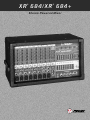
XR 684/XR 684+
®
®
S t e r e o P ow e r e d M i xe r
OWNER’S MANUAL
Intended to alert the user to the presence of uninsulated “dangerous voltage” within the product’s
enclosure that may be of sufficient magnitude to constitute a risk of electric shock to persons.
Intended to alert the user of the presence of important operating and maintenance (servicing)
instructions in the literature accompanying the product.
CAUTION: Risk of electrical shock — DO NOT OPEN!
CAUTION: To reduce the risk of electric shock, do not remove cover. No user serviceable parts inside. Refer
servicing to qualified service personnel.
WARNING: To prevent electrical shock or fire hazard, do not expose this appliance to rain or moisture. Before
using this appliance, read the operating guide for further warnings.
Este símbolo tiene el propósito, de alertar al usuario de la presencia de “(voltaje) peligroso” que no tiene
aislamiento dentro de la caja del producto que puede tener una magnitud suficiente como para constituir
riesgo de corrientazo.
Este símbolo tiene el propósito de alertar al usario de la presencia de instruccones importantes sobre la
operación y mantenimiento en la literatura que viene con el producto.
PRECAUCION: Riesgo de corrientazo — No abra.
PRECAUCION: Para disminuír el riesgo de corrientazo, no abra la cubierta. No hay piezas adentro que el usario
pueda reparar. Deje todo mantenimiento a los técnicos calificados.
ADVERTENCIA: Para evitar corrientazos o peligro de incendio, no deje expuesto a la lluvia o humedad este
aparato Antes de usar este aparato, Iea más advertencias en la guía de operación.
Ce symbole est utilisé pur indiquer à l’utilisateur la présence à l’intérieur de ce produit de tension nonisolée dangereuse pouvant être d’intensité suffisante pour constituer un risque de choc électrique.
Ce symbole est utilisé pour indiquer à l’utilisateur qu’il ou qu’elle trouvera d’importantes instructions sur
l’utilisation et l’entretien (service) de l’appareil dans la littérature accompagnant le produit.
ATTENTION: Risques de choc électrique — NE PAS OUVRIR!
ATTENTION: Afin de réduire le risque de choc électrique, ne pas enlever le couvercle. Il ne se trouve à l’intérieur
aucune pièce pouvant être reparée par l’utilisateur. Confier I’entretien à un personnel qualifié.
AVERTISSEMENT: Afin de prévenir les risques de décharge électrique ou de feu, n’exposez pas cet appareil à la
pluie ou à l’humidité. Avant d’utiliser cet appareil, lisez les avertissements supplémentaires situés dans le guide.
Dieses Symbol soll den Anwender vor unisolierten gefährlichen Spannungen innerhalb des Gehäuses
warnen, die von Ausreichender Stärke sind, um einen elektrischen Schlag verursachen zu können.
Dieses Symbol soll den Benutzer auf wichtige Instruktionen in der Bedienungsanleitung aufmerksam
machen, die Handhabung und Wartung des Produkts betreffen.
VORSICHT: Risiko — Elektrischer Schlag! Nicht öffnen!
VORSICHT: Um das Risiko eines elektrischen Schlages zu vermeiden, nicht die Abdeckung enfernen. Es befinden
sich keine Teile darin, die vom Anwender repariert werden könnten. Reparaturen nur von qualifiziertem
Fachpersonal durchführen lassen.
ACHTUNG: Um einen elektrischen Schlag oder Feuergefahr zu vermeiden, sollte dieses Gerät nicht dem Regen
oder Feuchtigkeit ausgesetzt werden. Vor Inbetriebnahme unbedingt die Bedienungsanleitung lesen.
2
ENGLISH
XR™ 684/684+ Powered Sound Reinforcement Mixing Console
General Description:
Congratulations on your purchase of the XR™ 684/684+ powered mixer. Within one compact unit, we
have packed feature after feature, each displaying the latest technology available. Both the XR 684
and the XR 684+ are covered in this guide. The two units share the same preamp functions. They
are different only in the power amp as noted below. Throughout this manual, the term “XR 684” will
refer to both units unless otherwise noted. Here are several features found on your XR 684:
• 8 low-noise, low-Z mic preamps
• 4 true high-Z 1/4" mic inputs
• 3-band equalization (Channels 1—8)
• Monitor send (each channel)
• EFX send (Channels 1—8)
• -25 dB pad (Channels 1—6)
• Low-cut filter (Channels 1—6)
• Stereo line inputs (Channels 7—9)
• 16-bit, DSP-based stereo reverb/effects with two parameter controls
• Two 9-band graphic EQs with FLS® Feedback Locating System®
• 48 V phantom power
• Stereo/Main-Monitor mode switch
• 2x200 W @ 4 ohms internal power amplifier (XR 684 only)
• 420 W @ 8 ohms in bridge mode (XR 684 only)
• 2x400 W @ 4 ohms internal power amplifier (XR 684+ only)
• DDT™ speaker protection
The standard channels (1—4) feature discrete low noise mic preamps with globally switched
phantom power, true high-impedance 1/4" mic inputs, low-cut filters, and three-band EQs. Two
additional channels (5—6) offer balanced XLR mic inputs and 1/4" line level inputs. Finally, there are
three stereo channels (7—9) for tape, CD, or synth inputs.
The master section features a unique graphic equalizer/power amp mode switch. Without patching,
the XR 684 can be used as a full stereo mixer amplifier (default). In the Main/Monitor mode, one
graphic and amplifier can be used for monitor and the other graphic and amplifier for the main L and
R (mono) signal.
Also included in the master section are 16 stereo digital effects from the award winning Deltafex™
digital signal processor. By including separate Time/Size and Color/Tone controls, the user can
create many effect settings from the 16 we provided. All channels, except Channel 9, have a
dedicated digital effects send routed directly to the DSP effects processor.
To take advantage of the XR 684’s powerful features, please read this owner’s manual carefully
and keep it as a reference. This manual includes several sections detailing individual areas of mixer
operation, including: control functions, set-up, and applications in sound reinforcement.
3
CHANNEL SECTION:
CHANNELS 1-4
1. MIC INPUT: XLR balanced, low-impedance channel input optimized for a
microphone or other low-level source. Pin 2 is the positive input. Because of the
wide range of gain adjustment, signal levels as high as +10 dBV (2.45 V RMS)
can be accommodated. When the phantom power is enabled, this connector
has +48 V on pins 2 and 3 with pin 1 as the ground reference. (The Mic Input
can also be found on channels 5 through 8.)
2. HI-Z/LINE INPUT: 1/4" balanced TRS high-impedance input. The tip is the
positive input, which can also be used for unbalanced inputs. A Pad (#3) switch
is provided to attenuate strong signals present at this input. Within the same
channel, the mic input and the Hi-Z/Line input cannot be used simultaneously.
9
8
7
3. PAD: Attenuates the input signal by 25 dB. If you find that barely touching
the Level control (#4) gives you an enormous increase in volume or if distortion
occurs, try using the Pad switch. In addition to increasing the dynamic range,
the channel input can now accommodate a higher input level before clipping.
This may be necessary with a close mic on loud guitar amplifiers or drum kits.
(The Pad switch can also be found on channels 5 and 6).
4. LEVEL: Sets the signal level sent to the Left and Right bus. (The level
control can also be found on channels 5 through 9.)
5. MON: Adjusts the level of the channel signal (pre-EQ) that is added to the
Monitor mix. (The Monitor control can also be found on channels 5 through 9.)
This control is independent of the main channel level control (#4).
6
5
4
6. LOW EQ: A shelving type of active tone control that varies the bass
frequency levels ±15 dB at 70 Hz. It will add depth to thin signals, or clean up
muddy ones. (The low control can also be found on channels 5 through 9.)
7. MID EQ: Mid ±15 dB. This control sets the amount of cut and boost at the
mid-frequency. (The mid control can also be found on channels 5 through 8.)
8. HIGH EQ: A shelving type of active tone control that varies the treble
frequency levels ±15 dB at 12 kHz. It is designed to remove noise or to add brilliance to the signal, depending on the quality of the source. (The high control
can also be found on channels 5 through 9.)
9. EFX: This control varies the level into the digital effects processor bus
adjusting the signal level from the particular channel to the digital processor.
(The effects control can also be found on channels 5 through 8.) The channel
level control (#4) also affects this level.
4
3
2
1
NOTE: Channels 5-9 contain features that differ from the previous channels.
Only those features are mentioned below. For information on features not
mentioned please refer to the section for Channels 1-4.
11
CHANNELS 5-6
10. LINE: 1/4" balanced TRS input for line level signals. This signal is connected
through a 25 dB pad to the mic input below it.
11. LOW CUT: This is a low-cut filter with a corner frequency of 80 Hz used to
filter rumble, wind noise, breath thumps, stage noise, and other low-frequency
components that rob power from the amplifiers and muddy the signal. Depressing
this switch will affect channels 1-6 only. Use of the filter will not affect the Monitor
signal.
CHANNELS 7-8
12. RIGHT INPUT: High-impedance 1/4" input for line-level signals. The Right
Input is adjusted by the Level control (#4). The signal is then routed to the internal
power amp. If the XR 684 is in Left/Right mode then the signal will go to the Right
Speaker Output (#37). In Mon/Main mode the signal is combined with the Left
and placed on the Main Speaker Output. The right signal can also be patched out
of the XR 684 via the Right Output jack (#31) to external components such as
effects, power amps, and recording devices.
13. LEFT/MONO INPUT: High-impedance 1/4" input for line-level signals. The
Left/Mono input supplies signal to both the Left and Right channels (if there is
nothing inserted to the right input jack) through the Level control (#4). In
Left/Right mode the signal will go to the Left Speaker Output (and Right Speaker
Output if nothing is inserted to the right input jack). In Mon/Main mode the signal
is combined with the Right and placed on the Main Speaker Output.
13
12
10
CHANNEL 9
14. TAPE IN: This stereo RCA phono jack accepts a stereo input (nominally
-10 dBV) from the output of a tape deck or CD player and places it on the Left
and Right channels as well as the Monitor Mix.
15. TAPE OUT: This stereo RCA phono jack provides a signal for the recording
inputs of a stereo tape deck.
CAUTION: DO NOT HOOK THE TAPE IN AND TAPE OUT TO THE INPUT AND
OUTPUT OF THE SAME DECK. DOING SO WILL FORM A LOOP
CAUSING SEVERE FEEDBACK. USE SEPERATE DECKS FOR
RECORDING AND PLAYBACK.
14
MASTER SECTION:
16. EFFECTS PEAK LED: Illuminates to indicate -6 dB of headroom before the
signals being sent to the effects circuit are clipped. Ideally, you would want this
LED to light only occassionally if at all. An occassional blink indicates that you
have the levels at an optimum setting. It is advisable to listen carefully to the
output at the same time in order to determine the final setting.
5
15
17. PRESET: Selects the effect preset from the list below.
EFX Presets
PRESET
1
2
3
4
5
6
7
8
9
10
11
12
13
14
15
16
NAME
Chamber
Plate
Room
Cathedral
Spring
Gate
Reverse
Delay + Reverb
Bright Delay
Warm Delay
Dark Delay
Ping Pong Delay
Chorus
Phaser
Flange
Rotary Speaker
TIME/SIZE
Time: 150 to 5,000 ms
Time: 100 to 4,000 ms
Time: 150 to 5,000 ms
Time: 100 to 8,000 ms
Time: 150 to 5,000 ms
Time: 150 to 500 ms
Time: 150 to 500 ms
Time: 0 to 225 ms
Time: 0 to 500 ms
Time: 0 to 500 ms
Time: 0 to 500 ms
Time: 0 to 500 ms
Rate: 0.125 to 8 Hz
Rate: 0.250 to 16 Hz
Rate: 0.10 to 2.5 Hz
High Speed: 0.50 to 25 Hz
COLOR/TONE
Damping (High Frequency)
Damping (High Frequency)
Damping (High Frequency)
Damping (High Frequency)
Damping (High Frequency)
Damping (High Frequency)
Damping (High Frequency)
Reverb Time: 0 to 5,000 ms
Feedback: 0 to 99%
Feedback: 0 to 99%
Feedback: 0 to 99%
Feedback: 0 to 99%
Depth: Best Set Full CW
Depth: Best Set Full CW
Depth: Best Set Full CW
Width: 0 to 100% CW
18. TIME/SIZE: In Reverb and Delay presets, this control adjusts the time of the particular reverb or delay;
in Chorus, Phaser, and Flange, it adjusts the rate of each. In Rotary Speaker setting, this adjusts the speed
of the speaker rotation.
19. COLOR/TONE: Adjusts the high-frequency content of the effects signal. (While using a delay this
control adjusts the feedback or depth.)
20. EFX TO MON: Controls the amount of effects signal sent to the monitor mix. This control allows effects
to be heard from the stage via the monitor.
21. EFX TO MAIN: Controls the amount of effects signal sent to the main mix.
22. FLS® (Feedback Locator System®): These LEDs illuminate to indicate the frequency band of highest
energy. When feedback occurs, this system will automatically indicate the graphics slider to use to decrease
that frequency band’s gain in order to lessen or eliminate feedback. (NOTE: These LEDs illuminate with any
audio signal, not just during feedback.)
23. GRAPHIC EQUALIZERS: These nine-band equalizers are fixed on one-octave centers. They are
designed for 12 dB of cut and 12 dB boost. They are connected directly to their power amplifier inputs.
24. SYSTEM MODE: This switch is used to configure the XR 684 as either a stereo or dual mono amplifier.
It is recessed to prevent accidental switching during a performance. Use a non-metallic object to change the
switch position (e.g., a toothpick). The XR 684 is shipped from the factory in the default setting of Left Main to
the upper EQ and Right to the lower EQ. When this switch is depressed it switches the lower EQ to (mono)
PA Left + Right. The upper EQ then becomes the monitor signal only, creating an entire PA and monitor mixing system in one small, easy-to-carry package. And this change is accomplished without a single patch cord!
25. MONITOR LEVEL: Sets the overall level of the monitor signal that is sent to the Monitor Output Jack.
This control also sets the monitor level going to the power amp when in Main/Monitor mode (see System
Mode #24).
6
17
18
19
20
21
16
33
22
23
25
24
22
26
23
27
28
29
30
31
32
26. MAIN LEVEL: This is the master level control for the main mix sent to the Left/Mono and Right output
jacks. This control sets the Main level going to the power amp when in Main/Monitor mode (see System
Mode #24). A good starting position for this control is the center detent position (12:00).
27. PHANTOM POWER SWITCH: Applies 48 V DC voltage to all input XLR connectors to power microphones that require it.
CAUTION! When phantom power is switched on, make sure that any channel you are plugging a mic into is
turned down in both the main and monitor mixes. Otherwise, there will be a loud pop in the PA. This is
normal. It is best to plug all mics into their respective channels with the phantom power switched off.
This reduces noise in the PA and reduces the chances of the mic being damaged. If phantom power is used,
do not connect unbalanced microphones or other devices that cannot handle this voltage to the XLR inputs.
(Some wireless receivers may be damaged; consult their manuals for compatibility.) The line input 1/4" jacks
are not connected to the phantom supply, and are safe for all inputs (balanced or unbalanced). An unbalanced-to-balanced impedance converter, such as the Peavey 5116 or a Peavey 1:1 Interface Adapter, can
also be used to isolate a mic from phantom voltage.
28. EFX DEFEAT: This 1/4" jack accepts an on/off 1/4" footswitch (Peavey Pt. #00051000) to defeat the
effects of both the Main and Monitor mixes.
29. MONITOR OUTPUT: This 1/4" jack provides an output from the monitor mix to supply external power
amp/monitor combinations. The level of this signal is determined by the Monitor Level control.
7
30. LEFT/MONO OUTPUT: This 1/4" jack provides an output from the Left Main mix to supply external
amp/speaker combinations. The level of this signal is determined by the Main Level control. When no plug is
connected to the Right Output (#31) then the right signal is mixed with the left, and both can be accessed at
the Left/Mono Output. This works well when you use the internal amps for monitor and external amps for
Main. Only one patch cord is required to get the Main out to the external amp.
31. RIGHT OUTPUT: This 1/4" jack provides an output from the Right Main mix to supply external
amp/speaker combinations. The level of this signal is determined by the Main Level control.
32. POWER AMP INPUTS: Plugging into these jacks allows the user to go directly into the Graphic
Equalizer, then into its respective power amplifier channel.
33. POWER LED: The power on LED indicator will light when the unit is powered.
AC POWER AND POWER AMPLIFIER SECTION:
34. A/C POWER INLET: This is the receptacle for an IEC line cord, which provides AC power to the
mixer/amplifier. Connect the line cord to this connector to provide power to the unit. Damage to the
equipment may result if improper line voltage is used (see line voltage marking on unit).
35. POWER: The mixer’s main power switch. The power on LED indicator (#33) will light when the unit is
powered.
34
36. FUSE: This is the main safety fuse for the AC line voltage. Only
replace the fuse with one the exact same type and rating. IF THE
FUSE CONTINUES TO OPEN, DO NOT OVER FUSE. TAKE
THE UNIT TO AN AUTHORIZED PEAVEY SERVICE CENTER!
36
35
37. PARALLEL LEFT/RIGHT SPEAKER OUTPUTS: These 1/4" jacks
are the amplifier’s output. By connecting a speaker cable to this
jack and to a speaker cabinet, you complete the signal chain. You
will notice that there are two pairs of jacks with another jack in the
middle. The two pairs are your two (stereo) amp outputs. Two cabinets
can be connected to each channel, as long as the combined impedance
of the cabinets is not less than 4 ohms. (i.e., two 8 ohms cabinets in
parallel = 4 ohms, four 16 ohms speakers in parallel = 4 ohms, etc.).
38. BRIDGE OUTPUT (XR 684 only): The bridge output of the XR
684 allows the power of the left and right amplifiers to be combined into
one mono output in applications where only one speaker will be used.
To use the bridge output, the system mode switch must be in the
Left/Right position. Connect an 8 ohm minimum impedance speaker to
the center bridge output jack.
37
38
37
CAUTION: When using the bridge output no other speakers should be connected to the adjacent parallel
speaker outputs. In addition, the minimum load for the XR 684 in bridge mode is 8 ohms. Do not allow
the total impedance to drop below 8 ohms or serious damage to the amplifier may occur.
8
9
PAD
TAPE/CD
INPUT
CHANNEL GAIN
LO M I D HI
EFX LEVEL
TONE CONTROL
LO HI
Mon Send
LO M I D HI
CHANNEL GAIN
LO M I D HI
LO HI
EFX LEVEL
TONE CONTROL
MONITOR SEND
Monitor Send
EFX LEVEL
TONE CONTROL
CHANNEL GAIN
MIC PREAMP
CHANNEL 9 (TAPE)
LO-Z INPUT
+48V PHANTON
RIGHT
LEFT/
MONO
STEREO LINE INPUT
CHANNELS 7-8
LO-Z INPUT
PAD
CHANNEL GAIN
LO MIDHI
TONE CONTROL
MONITOR SEND
MIC PREAMP
+48V PHANTON
LINE INPUT
CHANNELS 5-6
LO-Z INPUT
+48V PHANTON
MIC PREAMP
CHANNELS 1-4
HI-Z INPUT
Monitor
Master
Peak
LED
Low Cut
(80 Hz)
Monitor Output
Right Main Output
Right Power Amp Input
Left Power Amp Input
Left/Mono Main Output
Tape Out
Effects to Main
Mode Select
Effects to
Monitor
Effects
Selector
Time Color
Stereo
Digital
Effects
Effect Defeat
XR ® 684 BLOCK DIAGRAM
1-6 BUS
MON BUS
EFX BUS
LEFT BUS
RIGHT BUS
Right/Main
Left/Monitor
Left/Monitor
Power Amp Out
Bridge Out
Left/Monitor
Power Amp Out
210 WATTS PER CHANNEL • 4 OHMS
150 WATTS PER CHANNEL • 8 OHMS
BRIDGE 420 WATTS • 8 OHMS
Power Amp
DDT
Power Amp
DDT
10
LO-Z MIC
(NO PAD)
HI-Z
(W/PAD)
HI-Z MIC
(NO PAD)
LO-Z MIC
(W/PAD)
LINE/TAPE
INPUTS
-60
-50
-40
-30
-20
-10
0 dBu
+10
+20
+30
-60 dBu
-28 dBu
-35 dBu
-12.5 dBu
-11 dBu
+13.5 dBu
+21 dBu
2 dBu = 0 dBV
EQ
-15 dB
+15 dB
-10 dBV NOM.
MONITOR OUT
LEFT & RIGHT OUT
+22 dBu MAX
+22 dBu MAX
TAPE OUT
+10 dBV MAX
XR® 684 LEVELS
XR® 684 LEVEL DIAGRAM
-12 dB
+12 dB
TO POWER AMPS
+ 2 dBu NOMINAL
GRAPHIC EQ
XR® 684 IN - LEFT/RIGHT MODE
XR® 684 In - Left/Right Mode
Mains - Left
Mains - Right
Impulse™ 200
™
Impulse 200
Left/Monitor Outputs (Rear)
Right/Main Outputs (Rear)
Mode
Switch
Out
Reactor®
Tape Player
Out
PVM™ 22
MAQ™ 150
Tape Player In
Hi-Z Mic
Wireless
Mic/Gtr
L
R
Stereo Voice Module
Keyboard
11
SP™ 112M
XR® 684 IN - MONITOR/MAIN MODE
XR® 684 In - Monitor/Main Mode
Mains
Impulse™ 200
Monitors
SP™ 112M
Left/Monitor Outputs (Rear)
Right/Main Outputs (Rear)
Mode
Switch
Depressed
(In)
Reactor®
Tape Player
Out
PVM™ 22
Tape Player In
Wireless
Mic/Gtr
Hi-Z Mic
L
R
Stereo Voice Module
Keyboard
12
XR™ 684
SPECIFICATIONS:
Input Specifications:
Function
Input Z
(ohms)
Min
Lo-Z
(150 ohms)
2k
Channel 1-8
Hi-Z
100 k
Channel 1-4
Line Input
22 k
Channel 5-8
Tape
Channel 9
20 k
Input Gains
control
setting
Min**
Input Levels
Nominal*
Max
Max w/o pad
(50 dB)
-60 dBu
-30 dBu
-11 dBu
Max. w/pad
(25 dB)
-35 dBu
-5 dBu
+13.5 dBu
Max w/o pad
(50 dB)
-60 dBu
-30 dBu
-12 dBu
Max w/pad
(25 dB)
-35 dBu
-5 dBu
Max. w/o pad
(30 dB)
Max. w/pad
(5 dB)
-28 dBu
+2 dBu
-3 dBu
+27 dBu
-28 dBu
+2 dBu
Max. Gain
(30 dB)
Bal/
Connector
UnBal.
Bal.
XLR: Pin 1 Gnd,
Pin 2 (+), Pin 3 (-)
Bal.
1/4" TRS: Tip (+),
Ring (-),
Sleeve Ground
+12.5 dBu
+21 dBu Unbal. 1/4" TRS: Tip Send,
Ring Return,
+46 dBu
Sleeve Ground
+21 dBu Unbal. RCA Jacks
0 dBV=1V (RMS)
** Min input level (sensitivity) is the smallest signal that will produce nominal output (2 dBu) with channel and master
level controls set for maximum gain.
* Nominal settings are defined as all controls set a 0 dB (or 50% rotation for rotary pots)
XR 684 Output Specifications:
Function
Minimum Load Z
(ohms)
Output Level
Nominal
Max.
Bal./Unbal.
Connector
Main L/R
600
+2 dBu
+21 dbu
Unbal.
1/4" Phono Tip (+),
Sleeve Ground
Monitor
600
+2 dBu
+21 dBu
Unbal.
1/4" Phono Tip (+),
Sleeve Ground
Tape
10 k
-10 dBu
+10 dBu
Unbal.
RCA
+2 dBu = 0 dBV = 1V (RMS)
Gain:
Mic Input to L and R Output
Hi-Z Input to L and R Output
Line Input to L and R Output
60 dB (Max. Gain)
60 dB (Max. Gain)
30 dB (Max. Gain)
13
Frequency Response:
Mic Input to L - R Output
Line Input to L - R Output
To Power Amplifier Output
20 Hz — 20 kHz +0 dB/-1 dB
20 Hz — 20 kHz +0 dB/-1 dB
20 Hz — 20 kHz +0 dB/-1 dB
Total Harmonic Distortion (THD):
< 0.01% 20 Hz — 20 kHz mic input to L/R mon. output at nominal level (20 Hz — 80 kHz BW)
< 0.01% 20 Hz — 20 kHz line input to L/R output at output at nominal level (20 Hz — 80 kHz BW)
< .005% Typical at 1 kHz
Graphic Equalizer:
Filter Bandwidth
Filter Frequencies
Maximum Boost and Cut
1 octave
63, 125, 250, 500 1 k, 2 k, 4 k, 8 k, 16 k
+12 dB Boost, -12 dB Cut
XR 684 Hum and Noise:
Output
Residual Noise
Ref: 0 dBu
S/N Ratio
Ref: 2 dBu
Test Conditions
Main Left
and Right
-98 dBu
-100 dB
All controls down
-89 dBu
-91 dB
One channel nominal, master
nominal
-81 dBu
-83 dB
Master level nominal,
Channel level nominal, Mic
Inputs terminated @ 150 ohms
-96 dBu
-98 dB
All controls down
-90 dBu
-92 dB
One channel nominal, master
nominal
-81 dBu
-83 dB
Master level nominal,
Channel level nominal, Mic
Inputs terminated @ 150 ohms
Monitor
(Hum and noise measurements: 22 Hz to 22 kHz BW)
S/N Ratio:
> 85 dB below rated output (200 W/channel), mic/line to speaker output
Equivalent Input Noise (EIN):
-121.5 dBu (Input terminated with 150 ohms)
Crosstalk:
> 80 dB Adjacent Input Channels (20 Hz — 20 kHz)
> 70 dB Left to right outputs (20 Hz — 20 kHz)
Common Mode Rejection Ratio (Mic Input):
50 dB min. (20 Hz - 20 kHz)
60 dB typical @ 1 kHz
14
XR 684/400 SC AMPLIFIER SPECIFICATIONS
POWER SECTION
(400 SC Module with DDT™)
Hum and Noise:
-97 dB below 210 watts
Frequency Response:
+0, -1 dB, 20 Hz — 20 kHz @ rated power
Damping Factor:
Greater than 100 @ 1 kHz, 4 ohms
Rated Power:
• 210 watts RMS into 4 ohms, both channels
driven
• 150 watts RMS into 8 ohms, both channels
driven
• Bridge out 420 watts into 8 ohms*
*8 ohms minimum load for bridge output only
Input Sensitivity:
1.5 V RMS for 210 watts @ 4 ohms
Input Impedance:
2 k ohms
Power Requirements:
600 watts, 120 V AC, 60 Hz
Total Harmonic Distortion:
Less than .01% @ 1 kHz @ rated power
Dimensions:
Width:
19.125"
Height:
10.875"
Depth:
11.0"
Weight:
35.6 lbs.
DDT™ Dynamic Range:
Greater than 26 dB
DDT™ Maximum Distortion:
Below 0.5% THD for 6 dB overload
Below 1% THD for 20 dB overload
XR 684+/304D AMPLIFIER SPECIFICATIONS
Hum and Noise:
Stereo mode, both channels driven
Below rated output power, 4 ohms
Greater than -95 dB (A-weighted)
Frequency Response:
Stereo mode, both channels driven
+0.5, -3 dB, 1 W RMS, 4 ohms, 20 Hz to 20 kHz
The frequency response is internally controlled to
optimize phase linearity and improve transient
response.
Input Sensitivity:
1.2 V RMS for 400 watts @ 4 ohms
Rated Output Power (120 V AC, 60 Hz):
Stereo mode, both channels driven
4 ohms, 1 kHz, 400 W RMS per channel
8 ohms, 1 kHz, 250 W RMS per channel
Input Impedance:
10 k ohms
Power Requirements:
1,080 watts, 120 V AC, 60 Hz
Total Harmonic Distortion:
Stereo mode, both channels driven
1 kHz, 4 ohm rated output, Less than 0.2%
Dimensions:
Width:
19.125"
Height:
10.875"
Depth:
11.0"
Weight:
35.5 lbs.
DDT Dynamic Range:
Below 0.5% THD for 6 dB overload
Below 1% THD for 20 dB overload
™
15
PEAVEY ELECTRONICS CORPORATION LIMITED WARRANTY
Effective Date: July 1, 1998
What This Warranty Covers
Your Peavey Warranty covers defects in material and workmanship in Peavey products purchased and serviced in the U.S.A. and Canada.
What This Warranty Does Not Cover
The Warranty does not cover: (1) damage caused by accident, misuse, abuse, improper installation or operation, rental, product modification or
neglect; (2) damage occurring during shipment; (3) damage caused by repair or service performed by persons not authorized by Peavey; (4) products
on which the serial number has been altered, defaced or removed; (5) products not purchased from an Authorized Peavey Dealer.
Who This Warranty Protects
This Warranty protects only the original retail purchaser of the product.
How Long This Warranty Lasts
The Warranty begins on the date of purchase by the original retail purchaser. The duration of the Warranty is as follows:
Product Category
Duration
Guitars/Basses, Amplifiers, Pre-Amplifiers, Mixers, Electronic
Crossovers and Equalizers
2 years *(+ 3 years)
Drums
2 years *(+ 1 year)
Enclosures
3 years *(+ 2 years)
Digital Effect Devices and Keyboard and MIDI Controllers
1 year *(+ 1 year)
Microphones
2 years
Speaker Components (incl. speakers, baskets, drivers,
diaphragm replacement kits and passive crossovers)
and all Accessories
1 year
Tubes and Meters
90 days
[*denotes additional warranty period applicable if optional Warranty Registration Card is completed and returned to Peavey by original retail purchaser within 90
days of purchase.]
What Peavey Will Do
We will repair or replace (at Peavey's discretion) products covered by warranty at no charge for labor or materials. If the product or component must
be shipped to Peavey for warranty service, the consumer must pay initial shipping charges. If the repairs are covered by warranty, Peavey will pay the
return shipping charges.
How To Get Warranty Service
(1) Take the defective item and your sales receipt or other proof of date of purchase to your Authorized Peavey Dealer or Authorized Peavey
Service Center.
OR
(2) Ship the defective item, prepaid, to Peavey Electronics Corporation, International Service Center, 412 Highway 11 & 80 East, Meridian, MS 39301
or Peavey Canada Ltd., 95 Shields Court, Markham, Ontario, Canada L3R 9T5. Include a detailed description of the problem, together with a copy of
your sales receipt or other proof of date of purchase as evidence of warranty coverage. Also provide a complete return address.
Limitation of Implied Warranties
ANY IMPLIED WARRANTIES, INCLUDING WARRANTIES OF MERCHANTABILITY AND FITNESS FOR A PARTICULAR PURPOSE, ARE LIMITED
IN DURATION TO THE LENGTH OF THIS WARRANTY.
Some states do not allow limitations on how long an implied warranty lasts, so the above limitation may not apply to you.
Exclusions of Damages
PEAVEY'S LIABILITY FOR ANY DEFECTIVE PRODUCT IS LIMITED TO THE REPAIR OR REPLACEMENT OF THE PRODUCT, AT PEAVEY'S
OPTION. IF WE ELECT TO REPLACE THE PRODUCT, THE REPLACEMENT MAY BE A RECONDITIONED UNIT. PEAVEY SHALL NOT BE
LIABLE FOR DAMAGES BASED ON INCONVENIENCE, LOSS OF USE, LOST PROFITS, LOST SAVINGS, DAMAGE TO ANY OTHER EQUIPMENT
OR OTHER ITEMS AT THE SITE OF USE, OR ANY OTHER DAMAGES WHETHER INCIDENTAL, CONSEQUENTIAL OR OTHERWISE, EVEN IF
PEAVEY HAS BEEN ADVISED OF THE POSSIBILITY OF SUCH DAMAGES.
Some states do not allow the exclusion or limitation of incidental or consequential damages, so the above limitation or exclusion may not
apply to you.
This Warranty gives you specific legal rights, and you may also have other rights which vary from state to state.
If you have any questions about this warranty or service received or if you need assistance in locating an Authorized Service Center, please contact
the Peavey International Service Center at (601) 483-5365 / Peavey Canada Ltd. at (905) 475-2578.
Features and specifications subject to change without notice.
34
IMPORTANT SAFETY INSTRUCTIONS
WARNING: When using electric products, basic cautions should always be followed. including the following.
1. Read all safety and operating instructions before using this product.
2.
All safety and operating instructions should be retained for future reference.
3.
Obey all cautions in the operating instructions and on the back of the unit.
4.
All operating instructions should be followed.
5.
This product should not be used near water, i.e., a bathtub, sink, swimming pool, wet basement, etc.
6.
This product should be located so that its position does not interfere with its proper ventilation. It should not be placed flat against a wall
or placed in a built-in enclosure that will impede the flow of cooling air.
7.
This product should not be placed near a source of heat such as a stove, radiator, or another heat producing amplifier.
8.
Connect only to a power supply of the type marked on the unit adJacent to the power supply cord.
9.
Never break off the ground pin on the power supply cord. For more information on grounding, write
for our free booklet “Shock Hazard and Grounding."
10. Power supply cords should always be handled carefully. Never walk or place equipment on power supply cords. Periodically check cords for
cuts or signs of stress, especially at the plug and the point where the cord exits the unit.
11 The power supply cord should be unplugged when the unit is to be unused for long periods of time.
12. If this product is to be mounted in an equipment rack, rear support should be provided.
13. Metal parts can be cleaned with a damp rag. The vinyl covering used on some units can be cleaned with a damp rag or an ammonia-based
household cleaner if necessary. Disconnect unit from power supply before cleaning.
14. Care should be taken so that objects do not fall and liquids are not spilled into the unit through the ventilation holes or any other openings.
15. This unit should be checked by a qualified service technician if:
a. The power supply cord or plug has been damaged.
b. Anything has fallen or been spilled into the unit.
c. The unit does not operate correctly.
d. The unit has been dropped or the enclosure damaged.
16. The user should not attempt to service this equipment. All service work should]d be done by a qualified service technician.
17. This product should be used only with a cart or stand that is recommended by Peavey Electronics.
18. Exposure to extremely high noise ]levels may cause a permanent hearing loss. individuals vary considerably in susceptibility to noise induced
hearing loss, but nearly everyone will lose some hearing if exposed to sufficiently intense noise for a sufficient time. The U.S. Government’s
Occupational Safety and Health Administration (OSHA) has specified the following permissible noise level exposures.
Duration Per Day In Hours
8
6
4
3
2
1 1/2
1
1/2
1/4 or less
Sound Level dBA, Slow Response
90
92
95
97
100
102
105
110
115
According to OSHA, any exposure in excess of the above permissible limits could result in some hearing loss. Ear plugs or protectors h1 the ear
canal]s or over the ears must be worn when operating this amplification system in order to prevent a permanent hearing loss if exposure is in excess
of the limits as set forth above. To ensure against potentially dangerous exposure to high Sound pressure levels. it is recommended that all persons
exposed to equipment capable of producing high sound pressure levels such as this amplification system be protected by hearing protectors while
this unit is in operation.
SAVE THESE INSTRUCTIONS!
35
Features and specifications subject to change without notice.
Peavey Electronics Corporation • 711 A Street • Meridian • MS • 39301
(601) 483-5365 • FAX (601) 486-1278 • www.peavey.com
©2000
Printed in the U.S.A. 2/00