1
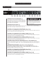
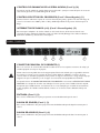
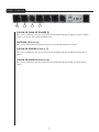
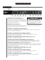
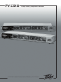
PV 23XO
®
2-Way Stereo/3-Way Mono Crossover
For more information on other great Peavey products, visit your local Peavey dealer or go online to www.peavey.com
Intended to alert the user to the presence of uninsulated “dangerous voltage” within the product’s
enclosure that may be of sufficient magnitude to constitute a risk of electric shock to persons.
Intended to alert the user of the presence of important operating and maintenance (servicing)
instructions in the literature accompanying the product.
CAUTION: Risk of electrical shock — DO NOT OPEN!
CAUTION: To reduce the risk of electric shock, do not remove cover. No user serviceable parts inside.
Refer servicing to qualified service personnel.
WARNING: To prevent electrical shock or fire hazard, this apparatus should not be exposed to rain or
moisture‚ and objects filled with liquids‚ such as vases‚ should not be placed on this apparatus. Before
using this apparatus‚ read the operating guide for further warnings.
Este símbolo tiene el propósito, de alertar al usuario de la presencia de “(voltaje) peligroso” sin
aislamiento dentro de la caja del producto y que puede tener una magnitud suficiente como para
constituir riesgo de descarga eléctrica.
Este símbolo tiene el propósito de alertar al usario de la presencia de instruccones importantes sobre la
operación y mantenimiento en la información que viene con el producto.
PRECAUCION: Riesgo de descarga eléctrica ¡NO ABRIR!
PRECAUCION: Para disminuír el riesgo de descarga eléctrica, no abra la cubierta. No hay piezas útiles
dentro. Deje todo mantenimiento en manos del personal técnico cualificado.
ADVERTENCIA: Para prevenir choque electrico o riesgo de incendios, este aparato no se debe exponer a
la lluvia o a la humedad. Los objetos llenos de liquidos, como los floreros, no se deben colocar encima
de este aparato. Antes de usar este aparato, lea la guia de funcionamiento para otras advertencias.
Ce symbole est utilisé dans ce manuel pour indiquer à l’utilisateur la présence d’une tension dangereuse
pouvant être d’amplitude suffisante pour constituer un risque de choc électrique.
Ce symbole est utilisé dans ce manuel pour indiquer à l’utilisateur qu’il ou qu’elle trouvera d’importantes
instructions concernant l’utilisation et l’entretien de l’appareil dans le paragraphe signalé.
ATTENTION: Risques de choc électrique — NE PAS OUVRIR!
ATTENTION: Afin de réduire le risque de choc électrique, ne pas enlever le couvercle. Il ne se trouve
à l’intérieur aucune pièce pouvant être reparée par l’utilisateur. Confiez I’entretien et la réparation de
l’appareil à un réparateur Peavey agréé.
AVIS: Dans le but de reduire les risques d’incendie ou de decharge electrique, cet appareil ne doit
pas etre expose a la pluie ou a l’humidite et aucun objet rempli de liquide, tel qu’un vase, ne doit
etre pose sur celui-ci. Avant d’utiliser de cet appareil, lisez attentivement le guide fonctionnant pour
avertissements supplémentaires.
Dieses Symbol soll den Anwender vor unisolierten gefährlichen Spannungen innerhalb des Gehäuses
warnen, die von Ausreichender Stärke sind, um einen elektrischen Schlag verursachen zu können.
Dieses Symbol soll den Benutzer auf wichtige Instruktionen in der Bedienungsanleitung aufmerksam
machen, die Handhabung und Wartung des Produkts betreffen.
VORSICHT: Risiko — Elektrischer Schlag! Nicht öffnen!
VORSICHT: Um das Risiko eines elektrischen Schlages zu vermeiden, nicht die Abdeckung enfernen.
Es befinden sich keine Teile darin, die vom Anwender repariert werden könnten. Reparaturen nur von
qualifiziertem Fachpersonal durchführen lassen.
WARNUNG: Um elektrischen Schlag oder Brandgefahr zu verhindern, sollte dieser Apparat nicht
Regen oder Feuchtigkeit ausgesetzt werden und Gegenstände mit Flüssigkeiten gefuellt, wie Vasen,
nicht auf diesen Apparat gesetzt werden. Bevor dieser Apparat verwendet wird, lesen Sie bitte den
Funktionsführer für weitere Warnungen.
2
IMPORTANT SAFETY INSTRUCTIONS
WARNING: When using electrical products, basic cautions should always be followed, including the following:
1.
2.
3.
4.
5.
6.
7.
8.
9.
10.
11.
12.
13.
14.
15.
16.
17.
18.
Read these instructions.
Keep these instructions.
Heed all warnings.
Follow all instructions.
Do not use this apparatus near water.
Clean only with a dry cloth.
Do not block any of the ventilation openings. Install in accordance with manufacturer’s instructions.
Do not install near any heat sources such as radiators, heat registers, stoves or other apparatus (including amplifiers)
that produce heat.
Do not defeat the safety purpose of the polarized or grounding-type plug. A polarized plug has two blades with one
wider than the other. A grounding type plug has two blades and a third grounding plug. The wide blade or third prong is
provided for your safety. If the provided plug does not fit into your outlet, consult an electrician for replacement of the
obsolete outlet.
Protect the power cord from being walked on or pinched, particularly at plugs, convenience receptacles, and the point
they exit from the apparatus.
Note for UK only: If the colors of the wires in the mains lead of this unit do not correspond with the terminals in your
plug‚ proceed as follows:
a) The wire that is colored green and yellow must be connected to the terminal that is marked by the letter E‚ the earth
symbol‚ colored green or colored green and yellow.
b) The wire that is colored blue must be connected to the terminal that is marked with the letter N or the color black.
c) The wire that is colored brown must be connected to the terminal that is marked with the letter L or the color red.
Only use attachments/accessories provided by the manufacturer.
Use only with a cart, stand, tripod, bracket, or table specified by the manufacturer, or sold with the apparatus. When a
cart is used, use caution when moving the cart/apparatus combination to avoid injury from tip-over.
Unplug this apparatus during lightning storms or when unused for long periods of time.
Refer all servicing to qualified service personnel. Servicing is required when the apparatus has been damaged in any
way, such as power-supply cord or plug is damaged, liquid has been spilled or objects have fallen into the apparatus,
the apparatus has been exposed to rain or moisture, does not operate normally, or has been dropped.
Never break off the ground pin. Write for our free booklet “Shock Hazard and Grounding.” Connect only to a power
supply of the type marked on the unit adjacent to the power supply cord.
If this product is to be mounted in an equipment rack, rear support should be provided.
Exposure to extremely high noise levels may cause a permanent hearing loss. Individuals vary considerably in susceptibility to noise-induced hearing loss, but nearly everyone will lose some hearing if exposed to sufficiently intense noise
for a sufficient time. The U.S. Government’s Occupational Safety and Health Administration (OSHA) has specified the
following permissible noise level exposures:
Duration Per Day In Hours
8
6
4
3
2
1 1⁄2
1
1⁄2
1⁄4 or less
Sound Level dBA, Slow Response
90
92
95
97
100
102
105
110
115
According to OSHA, any exposure in excess of the above permissible limits could result in some hearing loss. Ear plugs or protectors to
the ear canals or over the ears must be worn when operating this amplification system in order to prevent a permanent hearing loss, if
exposure is in excess of the limits as set forth above. To ensure against potentially dangerous exposure to high sound pressure levels, it is
recommended that all persons exposed to equipment capable of producing high sound pressure levels such as this amplification system be
protected by hearing protectors while this unit is in operation.
SAVE THESE INSTRUCTIONS!
3
WICHTIGE SICHERHEITSHINWEISE
ACHTUNG: Beim Einsatz von Elektrogeräten müssen u.a. grundlegende Vorsichtsmaßnahmen befolgt werden:
1.
2.
3.
4.
5.
6.
7.
8.
9.
10.
11.
12.
13.
14.
15.
16.
17.
18.
Lesen Sie sich diese Anweisungen durch.
Bewahren Sie diese Anweisungen auf.
Beachten Sie alle Warnungen.
Befolgen Sie alle Anweisungen.
Setzen Sie dieses Gerät nicht in der Nähe von Wasser ein.
Reinigen Sie es nur mit einem trockenen Tuch.
Blockieren Sie keine der Lüftungsöffnungen. Führen Sie die Installation gemäß den Anweisungen des Herstellers durch.
Installieren Sie das Gerät nicht neben Wärmequellen wie Heizungen, Heizgeräten, Öfen oder anderen Geräten (auch Verstärkern),
die Wärme erzeugen.
Beeinträchtigen Sie nicht die Sicherheitswirkung des gepolten Steckers bzw. des Erdungssteckers. Ein gepolter Stecker weist
zwei Stifte auf, von denen einer breiter ist als der andere. Ein Erdungsstecker weist zwei Stifte und einen dritten Erdungsstift auf.
Der breite Stift bzw. der dritte Stift dient Ihrer Sicherheit. Sollte der beiliegende Stecker nicht in Ihre Steckdose passen, wenden
Sie sich bitte an einen Elektriker, um die ungeeignete Steckdose austauschen zu lassen.
Schützen Sie das Netzkabel, sodass niemand darauf tritt oder es geknickt wird, insbesondere an Steckern oder Buchsen und
ihren Austrittsstellen aus dem Gerät.
Hinweis – Nur für Großbritannien: Sollte die Farbe der Drähte in der Netzleitung dieses Geräts nicht mit den Klemmen in Ihrem
Stecker übereinstimmen, gehen Sie folgendermaßen vor:
a) Der grün-gelbe Draht muss an die mit E (Symbol für Erde) markierte bzw. grüne oder grün-gelbe Klemme angeschlossen
werden.
b) Der blaue Draht muss an die mit N markierte bzw. schwarze Klemme angeschlossen werden.
c) Der braune Draht muss an die mit L markierte bzw. rote Klemme angeschlossen werden.
Verwenden Sie nur die vom Hersteller erhältlichen Zubehörgeräte oder Zubehörteile.
Verwenden Sie nur einen Wagen, Stativ, Dreifuß, Träger oder Tisch, der den Angaben des Herstellers entspricht oder zusammen
mit dem Gerät verkauft wurde. Wird ein Wagen verwendet, bewegen Sie den Wagen mit dem darauf befindlichen Gerät besonders
vorsichtig, damit er nicht umkippt und möglicherweise jemand verletzt wird.
Trennen Sie das Gerät während eines Gewitters oder während längerer Zeiträume, in denen es nicht benutzt wird, von der
Stromversorgung.
Lassen Sie sämtliche Wartungsarbeiten von qualifizierten Kundendiensttechnikern durchführen. Eine Wartung ist erforderlich,
wenn das Gerät in irgendeiner Art beschädigt wurde, etwa wenn das Netzkabel oder der Netzstecker beschädigt wurden,
Flüssigkeit oder Gegenstände in das Gerät gelangt sind, das Gerät Regen oder Feuchtigkeit ausgesetzt wurde, nicht normal
arbeitet oder heruntergefallen ist.
Der Erdungsstift darf nie entfernt werden. Auf Wunsch senden wir Ihnen gerne unsere kostenlose Broschüre „Shock Hazard and
Grounding“ (Gefahr durch elektrischen Schlag und Erdung) zu. Schließen Sie nur an die Stromversorgung der Art an, die am
Gerät neben dem Netzkabel angegeben ist.
Wenn dieses Produkt in ein Geräte-Rack eingebaut werden soll, muss eine Versorgung über die Rückseite eingerichtet werden.
Belastung durch extrem hohe Lärmpegel kann zu dauerhaftem Gehörverlust führen. Die Anfälligkeit für durch Lärm bedingten
Gehörverlust ist von Mensch zu Mensch verschieden, das Gehör wird jedoch bei jedem in gewissem Maße geschädigt, der über
einen bestimmten Zeitraum ausreichend starkem Lärm ausgesetzt ist. Die US-Arbeitsschutzbehörde (Occupational and Health
Administration, OSHA) hat die folgenden zulässigen Pegel für Lärmbelastung festgelegt:
Dauer pro Tag in Stunden
Geräuschpegel dBA, langsame Reaktion
8
6
4
3
2
1 1⁄2
1
1
⁄2
1
⁄4 oder weniger
90
92
95
97
100
102
105
110
115
Laut OSHA kann jede Belastung über den obenstehenden zulässigen Grenzwerten zu einem gewissen Gehörverlust führen. Sollte
die Belastung die obenstehenden Grenzwerte übersteigen, müssen beim Betrieb dieses Verstärkungssystems Ohrenstopfen oder
Schutzvorrichtungen im Gehörgang oder über den Ohren getragen werden, um einen dauerhaften Gehörverlust zu verhindern. Um sich vor
einer möglicherweise gefährlichen Belastung durch hohe Schalldruckpegel zu schützen, wird allen Personen empfohlen, die mit Geräten
arbeiten, die wie dieses Verstärkungssystem hohe Schalldruckpegel erzeugen können, beim Betrieb dieses Geräts einen Gehörschutz zu tragen.
BEWAHREN SIE DIESE SICHERHEITSHINWEISE AUF!
4
INSTRUCTIONS IMPORTANTES DE SECURITE
ATTENTION: L’utilisation de tout appareil électrique doit être soumise aux precautions d’usage incluant:
1.
2.
3.
4.
5.
6.
7.
8.
9.
10.
11.
12.
13.
14.
15.
16.
17.
18.
Lire ces instructions.
Gardez ce manuel pour de futures références.
Prétez attention aux messages de précautions de ce manuel.
Suivez ces instructions.
N’utilisez pas cette unité proche de plans d’eau.
N’utilisez qu’un tissu sec pour le nettoyage de votre unité.
N’obstruez pas les systèmes de refroidissement de votre unité et installez votre unité en fonction des instructions
de ce manuel.
Ne positionnez pas votre unité à proximité de toute source de chaleur.
Connectez toujours votre unité sur une alimentation munie de prise de terre utilisant le cordon d’alimentation
fourni.
Protégez les connecteurs de votre unité et positionnez les cablages pour éviter toutes déconnexions accidentelles.
Note pour les Royaumes-Unis: Si les couleurs de connecteurs du cable d’alimentation ne correspond pas au guide
de la prise secteur, procédez comme suit:
a) Le connecteur vert et jaune doit être connectrer au terminal noté E, indiquant la prise de terre ou correspondant
aux couleurs verte ou verte et jaune du guide.
b) Le connecteur Bleu doit être connectrer au terminal noté N, correspondnat à la couleur noire du guide.
c) Le connecteur marron doit être connectrer au terminal noté L, correspondant à la couleur rouge du guide..
N’utilisez que des fixations approuvées par le fabriquant.
Lors de l’utilsation sur pied ou pole de support, assurez dans le cas de déplacement de l’ensemble enceinte/
support de prévenir tout basculement intempestif de celui-ci.
Il est conseillé de déconnecter du secteur votre unité en cas d’orage ou de durée prolongée sans utilisation.
Seul un technicien agréé par le fabriquant est à même de réparer/contrôler votre unité. Celle-ci doit être contrôlée si
elle a subit des dommages de manipulation, d’utilisation ou de stockage (humidité,…).
Ne déconnectez jamais la prise de terre de votre unité.
Si votre unité est destinée a etre montée en rack, des supports arriere doivent etre utilises.
Une exposition à de hauts niveaux sonores peut conduire à des dommages de l’écoute irréversibles. La susceptibilité au bruit varie considérablement d’un individu à l’autre, mais une large majorité de la population expériencera
une perte de l’écoute après une exposition à une forte puissance sonore pour une durée prolongée. L’organisme de
la santé américaine (OSHA) a produit le guide ci-dessous en rapport à la perte occasionnée:
Durée par Jour (heures)
8
6
4
3
2
1 1⁄2
1
1
⁄2
1
⁄4 ou inférieur
Niveau sonore moyen (dBA)
90
92
95
97
100
102
105
110
115
D’après les études menées par le OSHA, toute exposition au delà des limites décrites ce-dessus entrainera des pertes de l’écoute chez la
plupart des sujets. Le port de système de protection (casque, oreilette de filtrage,…) doit être observé lors de l’opération cette unité ou des
dommages irréversibles peuvent être occasionnés. Le port de ces systèmes doit être observé par toutes personnes susceptibles d’être exposées à des conditions au delà des limites décrites ci-dessus.
GARDEZ CES INSTRUCTIONS!
5
INSTRUCCIONES IMPORTANTES PARA SU SEGURIDAD
CUIDADO: Cuando use productos electrónicos, debe tomar precauciones básicas, incluyendo las siguientes:
1.
2.
3.
4.
5.
6.
7.
8.
9.
10.
11.
12.
13.
14.
15.
16.
17.
18.
Lea estas instrucciones.
Guarde estas instrucciones.
Haga caso de todos los consejos.
Siga todas las instrucciones.
No usar este aparato cerca del agua.
Limpiar solamente con una tela seca.
No bloquear ninguna de las salidas de ventilación. Instalar de acuerdo a las instrucciones del fabricante.
No instalar cerca de ninguna fuente de calor como radiadores, estufas, hornos u otros aparatos (incluyendo amplificadores)
que produzcan calor.
No retire la patilla protectora del enchufe polarizado o de tipo “a Tierra”. Un enchufe polarizado tiene dos puntas, una
de ellas más ancha que la otra. Un enchufe de tipo “a Tierra” tiene dos puntas y una tercera “a Tierra”. La punta ancha (
la tercera ) se proporciona para su seguridad. Si el enchufe proporcionado no encaja en su enchufe de red, consulte a un
electricista para que reemplaze su enchufe obsoleto.
Proteja el cable de alimentación para que no sea pisado o pinchado, particularmente en los enchufes, huecos, y los puntos
que salen del aparato.
Nota para el Reino Unido solamente: Si los colores de los cables en el enchufe principal de esta unidad no corresponden
con los terminales en su enchufe‚ proceda de la siguiente manera:
a) El cable de color verde y azul debe ser conectado al terminal que está marcado con la letra E‚ el símbolo de Tierra
(earth)‚ coloreado en verde o en verde y amarillo.
b) El cable coloreado en azul debe ser conectado al terminal que está marcado con la letra N o el color negro.
c) El cable coloreado en marrón debe ser conectado al terminal que está marcado con la letra L o el color rojo.
Usar solamente añadidos/accesorios proporcionados por el fabricante.
Usar solamente un carro, pie, trípode, o soporte especificado por el fabricante, o vendido junto al aparato. Cuando se use
un carro, tenga cuidado al mover el conjunto carro/aparato para evitar que se dañe en un vuelco. No suspenda esta caja de
ninguna manera.
Desenchufe este aparato durante tormentas o cuando no sea usado durante largos periodos de tiempo.
Para cualquier reparación, acuda a personal de servicio cualificado. Se requieren reparaciones cuando el aparato ha sido
dañado de alguna manera, como cuando el cable de alimentación o el enchufe se han dañado, algún líquido ha sido
derramado o algún objeto ha caído dentro del aparato, el aparato ha sido expuesto a la lluvia o la humedad, no funciona de
manera normal, o ha sufrido una caída.
Nunca retire la patilla de Tierra.Escríbanos para obtener nuestro folleto gratuito “Shock Hazard and Grounding” (“Peligro
de Electrocución y Toma a Tierra”). Conecte el aparato sólo a una fuente de alimentación del tipo marcado al lado del cable
de alimentación.
Si este producto va a ser enracado con más equipo, use algún tipo de apoyo trasero.
La exposición a altos niveles de ruido puede causar una pérdida permanente en la audición. La susceptibilidad a la pérdida
de audición provocada por el ruido varía según la persona, pero casi todo el mundo perderá algo de audición si se expone
a un nivel de ruido suficientemante intenso durante un tiempo determinado. El Departamento para la Salud y para la
Seguridad del Gobierno de los Estados Unidos (OSHA) ha especificado las siguientes exposiciones al ruido permisibles:
Duración por Día en Horas
8
6
4
3
2
1 1⁄2
1
1
⁄2
1
⁄4 o menos
Nivel de Sonido dBA, Respuesta Lenta
90
92
95
97
100
102
105
110
115
De acuerdo al OSHA, cualquier exposición que exceda los límites arriba indicados puede producir algún tipo de pérdida en la audición.
Protectores para los canales auditivos o tapones para los oídos deben ser usados cuando se opere con este sistema de sonido para prevenir una pérdida permanente en la audición, si la exposición excede los límites indicados más arriba. Para protegerse de una exposición a
altos niveles de sonido potencialmente peligrosa, se recomienda que todas las personas expuestas a equipamiento capaz de producir altos
niveles de presión sonora, tales como este sistema de amplificación, se encuentren protegidas por protectores auditivos mientras esta unidad esté operando.
GUARDE ESTAS INSTRUCCIONES!
6
ENGLISH
PV®23XO
2-Way Stereo/3-Way Mono Crossover
Description
Thank you for purchasing a Peavey Electronics PV 23XO 2-Way Stereo/3-Way Mono Crossover. The PV 23XO is a two dualchannel crossover incorporating Peavey’s legendary low-noise, low-distortion design. Ruggedly constructed, PV 23XO gives the
operator the flexibility to establish a two-way stereo system or run in a three-way mono configuration. The PV 23XO has variablestate filter controls with 24 dB per octave filters and utilizes XLR inputs and outputs for balanced operation from 20 Hz to 20 kHz.
Features
➡ 2-way stereo/3-way mono operation
➡ Variable-state filter controls
➡ 24 dB/octave filters
➡ XLR inputs and outputs for balanced operation
➡ 20 Hz to 20 kHz operation
7
ST E R E O M O D E O P E R AT I O N
F R O N T PA N E L
1
2
3
4
6
5
7
8
MODE SWITCH (2)
10
11
12
WARNING
POWER SWITCH (1)
This 2-position rocker switch applies mains power to the unit
when in the ON position. The red LED located to the right of
the Power switch indicates that power is ON.
9
THE ON/OFF SWITCH IN THIS APPARATUS
DOES NOT BREAK BOTH SIDES OF THE MAINS.
HAZARDOUS ENERGY MAY BE PRESENT INSIDE
THE ENCLOSURE WHEN THE POWER SWITCH IS
IN THE OFF POSITION.
This switch selects between stereo 2-way operation and mono 3-way operation. The red LED above the Mode
switch indicates mono mode.
INPUT GAIN CONTROL (Channel 1) (3)
This control is used to optimize the channel 1 gain between the mixer and the power amps for channel 1.
Control range is between 0 dB and +12 dB.
LOW GAIN CONTROL (Channel 1) (4)
Controls output level of channel 1 low frequency signal (signal below the selected crossover point) present at
channel 1 low output XLR.
HIGH GAIN CONTROL (Channel 1) (5)
Controls output level of channel 1 high frequency signal (signal above the selected crossover point) present at
channel 1 high output XLR.
CROSSOVER SELECTOR CONTROL (Channel 1 Lows/Highs) (6)
Allows user to choose their desired crossover point for lows and highs for channel 1. Control range is
between 100 Hz and 1 kHz or 1 kHz and 10 kHz depending on the position of the Range Switch.
RANGE (x10) SWITCH (Channel 1 lows/highs) (7)
This switch multiplies the value indicated on the Crossover Selector Control times 10. When engaged, the
range will change from 100 Hz to 1 kHz through 1 kHz to 10 kHz. Range x10 is indicated by illumination of
the red LED above the switch.
INPUT GAIN CONTROL (Channel 2) (8)
This control is used to optimize the channel 2 gain between the mixer and the power amps for channel 2.
Control range is between 0 dB and +12 dB.
LOW GAIN CONTROL (Channel 2) (9)
Controls output level of channel 2 lows signal (signal below the selected crossover point) present at channel 2
low output XLR.
8
HIGH GAIN CONTROL (Channel 2) (10)
This controls output level of channel 2 highs signal (signal above the selected crossover point) present at
channel 2 high output XLR.
CROSSOVER SELECTOR CONTROL (Channel 2 lows/highs) (11)
This allows users to choose their desired crossover point for lows and highs for channel 2. The control range
is between 100 Hz and 1 kHz or 1 kHz and 10 kHz, depending on the position of the Range switch.
RANGE (x10) SWITCH (Channel 2 lows/highs) (12)
This switch multiplies the value indicated on the Crossover Selector Control times 10. When engaged, the
range will change from 100 Hz to 1 kHz through 1 kHz to 10 kHz. Range x10 is indicated by the illumination
of the red LED above the switch.
R E A R PA N E L
4
3
2
1
IEC MAINS CONNECTOR (1)
This is a standard IEC power connector. An AC mains cord having the appropriate AC plug and ratings for
the intended operating voltage is included in the carton.
Never break off the ground pin on any equipment. It is provided for your safety. If the outlet used does
not have a ground pin, a suitable grounding adapter should be used and the third wire should be grounded
properly. To prevent the risk of shock or fire hazard, always make sure that the equalizer and all associated
equipment is properly grounded.
Incorporated into this IEC MAINS CONNECTOR is the MAINS FUSE HOLDER. If for any reason you
are unable to power up this unit, remove the fuse by pulling out the holder. Check to see if the fuse is
operational. If not, then replace with a fuse of the appropriate value and rating. If the fuse continues to fail
contact your nearest Certified Peavey Service Center.
INPUT (Channel 1) (2)
This XLR female 3-pin connector provides a balanced input for channel 1.
LOW OUTPUT (Channel 1) (3)
This XLR male 3-pin connector provides a balanced output for the low frequencies for channel 1.
HIGH OUTPUT (Channel 1) (4)
This XLR male 3-pin connector provides a balanced output for the high frequencies for channel 1.
9
R E A R PA N E L
8
7
6
5
LOW SUM OUTPUT (5)
This XLR male 3-pin connector provides a balanced output for the low frequencies for both channel 1 and
channel 2, which been summed (added) together.
INPUT (Channel 2) (6)
This XLR female 3-pin connector provides a balanced input for channel 2.
LOW OUTPUT (Channel 2) (7)
This XLR male 3-pin connector provides a balanced output for the low frequencies for channel 2.
HIGH OUTPUT (Channel 2) (8)
This XLR male 3-pin connector provides a balanced output for the high frequencies for channel 2.
10
M O N O M O D E O P E R AT I O N
F R O N T PA N E L
1
2
3
4
6
5
7
8
MODE SWITCH (2)
10
11
12
WARNING
POWER SWITCH (1)
This 2-position rocker switch applies mains power to the unit
when in the ON position. The red LED located to the right of
the Power switch indicates that Power is ON.
9
THE ON/OFF SWITCH IN THIS APPARATUS
DOES NOT BREAK BOTH SIDES OF THE MAINS.
HAZARDOUS ENERGY MAY BE PRESENT INSIDE
THE ENCLOSURE WHEN THE POWER SWITCH IS
IN THE OFF POSITION.
This switch selects between stereo 2-way operation and mono 3-way operation. The red LED above the Mode
switch indicates mono mode.
INPUT GAIN CONTROL (3)
This control is used to optimize the gain between the mixer and the power amps. The control range is
between 0 dB and +12 dB.
LOW GAIN CONTROL (4)
This controls the output level of low frequency signals (those below the selected crossover point) present at
the low output XLR.
HIGH GAIN CONTROL (Channel 1) (5)
This function is non-operational in MONO Mode.
CROSSOVER SELECTOR CONTROL (lows/mids) (6)
This allows the user to choose their desired crossover point for lows and mids. Control range is between 100
Hz and 1 kHz or 1 kHz and 10 kHz depending on the position of the Range Switch.
RANGE (x10) SWITCH (lows/mids) (7)
This switch multiplies the value indicated on the Crossover Selector Control times 10. When engaged, the
range will change from 100 Hz to 1 kHz through 1 kHz to 10 kHz. Range x10 is indicated by the illumination
of the red LED above the switch.
INPUT GAIN CONTROL (Channel 2) (8)
This function is non operational in MONO Mode.
MID GAIN CONTROL (9)
This controls the output level of mid signals (those below the selected crossover point) present at mid output
XLR.
HIGH GAIN CONTROL (10)
This controls the output level of the highs (signals above the selected crossover point) present at high output
XLR.
11
CROSSOVER SELECTOR CONTROL (mids/highs) (11)
This allows users to choose their desired crossover point for mids and highs. The control range is between
100 Hz and 1 kHz or 1 kHz and 10 kHz, depending on the position of the Range switch.
RANGE (x10) SWITCH (mids/highs) (12)
This switch multiplies the value indicated on the Crossover Selector Control times 10. When engaged, the
range will change from 100 Hz to 1 kHz through 1 kHz to 10 kHz. Range x10 is indicated by the illumination
of the red LED above the switch.
R E A R PA N E L
4
3
2
1
IEC MAINS CONNECTOR (1)
This is a standard IEC power connector. An AC mains cord having the appropriate AC plug and ratings for
the intended operating voltage is included in the carton.
Never break off the ground pin on any equipment. It is provided for your safety. If the outlet used does
not have a ground pin, a suitable grounding adapter should be used and the third wire should be grounded
properly. To prevent the risk of shock or fire hazard, always make sure that the equalizer and all associated
equipment is properly grounded.
Incorporated into this IEC MAINS CONNECTOR is the MAINS FUSE HOLDER. If for any reason you
are unable to power up this unit, remove the fuse by pulling out the holder. Check to see if the fuse is
operational. If not, then replace with a fuse of the appropriate value and rating. If the fuse continues to fail
contact your nearest Certified Peavey Service Center.
INPUT (2)
This XLR female 3-pin connector provides a balanced input.
LOW OUTPUT (3)
This XLR male 3-pin connector provides a balanced output for the low frequencies.
HIGH OUTPUT (Channel 1) (4)
This function is non-operational in MONO Mode.
12
R E A R PA N E L
8
7
6
5
LOW SUM OUTPUT (5)
This function is non-operational in MONO Mode.
INPUT (Channel 2) (6)
This function is non-operational in MONO Mode.
MID OUTPUT (7)
This XLR male 3-pin connector provides a balanced output for the mid frequencies.
HIGH OUTPUT (8)
This XLR male 3-pin connector provides a balanced output for the high frequencies.
13
PV ®23XO
2-Way Stereo/3-Way Mono
SPECIFICATIONS
CONTROLS AND SWITCHES
Channel Gain Control: 0 to +12 dB
Low Frequency Level Control: -∞ to +6 dB
High Frequency Level Control: -∞ to +6 dB
Low Frequency to High Frequency crossover: 100 Hz to 1 Khz x10 range: Changes Low Frequency
to Mid Frequency from (100 Hz to 1 kHz) to
(1kHz to 10 kHz)
2-way stereo/3-way mono changes the unit from
2-way stereo or 3-way mono
FREQUENCY RESPONSE
Each output is -3 dB at the selected crossover frequency value. Outputs are essentially flat within their
relative passbands.
Distortion: Less than 0.02% THD @ +4 dBu,@ 1 kHz
Hum and Noise: Crossover controls set @ 1 kHz, all level controls set at 0 dB; 22 Hz to 22 kHz, unweighted gain @
0dB(ref +4dBu) - 90dB
Low Frequency Output: -86 dBu below 80 dB
High Frequency Output: -84 dBu below -78 dB
Maximum Input Level: +14 dBu, (channel gain @ 0 dB input level controls set at 0 dB) +22 dBu
Maximum Output Level: +22 dBu, unbalanced +28 dBu, balanced
Input Impedance: 10 k ohms unbalanced
CONNECTORS
Inputs: XLR Balanced
Outputs: XLR Balanced
Power Requirements: 120V AC, 50/60 Hz, 20 watts (domestic model)
14
DEUTSCH
PV®23XO
2-Wege Stereo/3-Wege Mono Frequenzweiche
Beschreibung
Vielen Dank, dass Sie sich für die Peavey Electronics PV 23XO 2-Wege-Stereo-/3-Wege-Mono-Frequenzweiche entschieden
haben. Die PV 23XO ist eine Zweikanal-Frequenzweiche in Peaveys legendärem geräusch- und verzerrungsarmen Design. Die
robust konstruierte PV 23XO bietet dem Benutzer die Möglichkeit, entweder ein 2-Wege-Stereo- oder ein 3-Wege-Monosystem
aufzubauen. Die PV 23XO besitzt variable Filterregler mit Filtern von 24 dB pro Oktave und verwendet XLR-Eingänge und Ausgänge für symmetrierten Betrieb zwischen 20 Hz und 20 kHz.
Merkmale
➡ 2-Wege-Stereo-/3-Wege-Mono-Betrieb
➡ Variable Filterregler
➡ 24 dB/Oktave-Filter
➡ XLR-Eingänge und -Ausgänge für symmetrierten Betrieb
➡ Betrieb zwischen 20 Hz und 20 kHz
15
STEREO-BETRIEB
VORDE RSEITE
1
2
3
4
6
5
7
8
MODE-SCHALTER (2)
10
11
12
WARNUNG
POWER-SCHALTER (1)
Steht dieser Kippschalter mit 2 Stellungen auf ON, wird das
Gerät mit Netzstrom versorgt. Die rote LED rechts vom
Netzschalter zeigt an, dass das Gerät am Netz ist (ON).
9
DER AN/AUS SCHALTER IN DIESEM GERÄT UNTERBRICHT
NICHT BEIDE SEITEN DES NETZES. AUCH WENN DER
SCHALTER AUF "AUS" STEHT KANN IM INNERN DES
GERÄTES IMMER NOCH GEFÄHRLICHE ELEKTRISCHE
ENERGIEN VORHANDEN SEIN.
Mit diesem Schalter wählen Sie zwischen Zweiwege-Stereo- oder Dreiwege-Mono-Betrieb. Die rote LED über
dem Mode-Schalter zeigt an, dass der Mono-Modus gewählt ist.
INPUT-GAIN-REGLER (Kanal 1) (3)
Mit diesem Regler lässt sich der Kanal-1-Gain zwischen Mischpult und Verstärkern für Kanal 1 optimieren. Der
Regelbereich beträgt 0 dB bis +12 dB.
LOW-GAIN-REGLER (Kanal 1) (4)
Regelt den Ausgangspegel des niederfrequenten Signals von Kanal 1 (Signal unter dem gewählten
Überschneidungspunkt) am XLR-Tiefenausgang von Kanal 1.
HIGH-GAIN-REGLER (Kanal 1) (5)
Regelt den Ausgangspegel des hochfrequenten Signals von Kanal 1 (Signal über dem gewählten
Überschneidungspunkt) am XLR-Höhenausgang von Kanal 1.
CROSSOVER-WAHLSCHALTER (Kanal 1 Tiefen/Höhen) (6)
Gestattet dem Anwender die Auswahl der gewünschten Übergangsfrequenz für die Tiefen und Höhen von
Kanal 1. Je nach Stellung des Range-Schalters liegt der Regelbereich zwischen 100 Hz und 1 kHz oder 1 kHz
und 10 kHz.
RANGE-SCHALTER (x10) (Kanal 1 Tiefen/Höhen) (7)
Ist dieser Schalter aktiviert, verzehnfacht sich der am CROSSOVER-Wahlschalter angezeigte Wert. In diesem
Fall ändert sich der Bereich von 100 Hz bis 1 kHz auf 1 kHz bis 10 kHz. Wenn „Range x10“ aktiv ist, leuchtet
die rote LED über dem Schalter.
INPUT-GAIN-REGLER (Kanal 2) (8)
Mit diesem Regler lässt sich der Kanal-2-Gain zwischen Mischpult und Verstärkern für Kanal 2 optimieren. Der
Regelbereich beträgt 0 dB bis +12 dB.
LOW-GAIN-REGLER (Kanal 2) (9)
Regelt den Ausgangspegel der niederfrequenten Signale von Kanal 2 (Signal unter der gewählten
Übergangsfrequenz) am XLR-Tiefenausgang von Kanal 2.
16
HIGH-GAIN-REGLER (Kanal 2) (10)
Regelt den Ausgangspegel des hochfrequenten Signals von Kanal 2 (Signal über der gewählten
Übergangsfrequenz) am XLR-Höhenausgang von Kanal 2.
CROSSOVER-WAHLSCHALTER (Kanal 2 Tiefen/Höhen) (11)
Gestattet dem Anwender die Auswahl der gewünschten Übergangsfrequenz für die Tiefen und Höhen von
Kanal 2. Je nach Stellung des Bereichs-Schalters liegt der Regelbereich zwischen 100 Hz und 1 kHz oder 1
kHz und 10 kHz.
RANGE-SCHALTER (x10) (Kanal 2 Tiefen/Höhen) (12)
Ist dieser Schalter aktiviert, verzehnfacht sich der am CROSSOVER-Wahlschalter angezeigte Wert. In diesem
Fall ändert sich der Bereich von 100 Hz bis 1 kHz auf 1 kHz bis 10 kHz. Wenn „Range x10“ aktiv ist, leuchtet
die rote LED über dem Schalter.
RÜCKSEITE
4
3
2
1
IEC-NETZSTECKER (1)
Hierbei handelt es sich um einen genormten IEC-Netzstecker. Ein Wechselstrom-Netzkabel mit
dem entsprechenden Wechselstromstecker und den entsprechenden Werten für die erforderliche
Betriebsspannung liegt bei.
Der Erdungsstift eines Geräts darf keinesfalls entfernt werden. Er ist zu Ihrer Sicherheit vorhanden. Fehlt der
Erdungsstift an der verwendeten Steckdose, muss ein geeigneter Erdungsadapter verwendet und die dritte
Ader korrekt geerdet werden. Um elektrische Schläge oder Brände auszuschließen, müssen der Equalizer
sowie sämtliche zugehörigen Ausrüstungsteile korrekt geerdet werden.
In den IEC-NETZSTECKER ist der NETZSICHERUNGSHALTER integriert. Lässt sich dieses Gerät aus
irgendeinem Grund nicht einschalten, entfernen Sie die Sicherung, indem Sie den Halter herausziehen.
Überprüfen Sie, ob die Sicherung betriebsbereit ist. Ist dies nicht der Fall, ersetzen Sie diese Sicherung durch
eine Sicherung gleichen Typs mit dem gleichen Wert. Sollte die Sicherung weiter Probleme bereiten, wenden
Sie sich an ein zugelassenes Peavey-Service-Center in Ihrer Nähe.
INPUT (Kanal 1) (2)
This XLR female 3-pin connector provides a balanced input for channel 1.
LOW OUTPUT (Kanal 1) (3)
Diese 3-Pin-Buchse (XLR-male) sorgt für einen symmetrierten Ausgang der niedrigen Frequenzen für Kanal 1.
HIGH OUTPUT (Kanal 1) (4)
Diese 3-Pin-Buchse (XLR-male) sorgt für einen symmetrierten Ausgang der hohen Frequenzen für Kanal 1.
17
R E A R PA N E L
8
7
6
5
LOW SUM OUTPUT (5)
Diese 3-Pin-Buchse (XLR-male) sorgt für einen symmetrierten Ausgang der summierten niedrigen Frequenzen
für Kanal 1 und Kanal 2.
INPUT (Kanal 2) (6)
Diese 3-Pin-Buchse (XLR-female) sorgt für einen symmetrierten Eingang für Kanal 2.
LOW OUTPUT (Kanal 2) (7)
Diese 3-Pin-Buchse (XLR-male) sorgt für einen symmetrierten Ausgang der niedrigen Frequenzen für Kanal 2.
HIGH OUTPUT (Kanal 2) (8)
Diese 3-Pin-Buchse (XLR-male) sorgt für einen symmetrierten Ausgang der hohen Frequenzen für Kanal 2.
18
MONO-BETRIEB
VORDE RSEITE
1
2
3
4
6
5
7
8
MODE-SCHALTER (2)
10
11
12
WARNUNG
POWER-SCHALTER (1)
Steht dieser Kippschalter mit 2 Stellungen auf ON, wird das
Gerät mit Netzstrom versorgt. Die rote LED rechts vom
Netzschalter zeigt an, dass das Gerät am Netz ist (ON).
9
DER AN/AUS SCHALTER IN DIESEM GERÄT UNTERBRICHT
NICHT BEIDE SEITEN DES NETZES. AUCH WENN DER
SCHALTER AUF "AUS" STEHT KANN IM INNERN DES
GERÄTES IMMER NOCH GEFÄHRLICHE ELEKTRISCHE
ENERGIEN VORHANDEN SEIN.
Mit diesem Schalter wählen Sie zwischen Zweiwege-Stereo- oder Dreiwege-Mono-Betrieb. Die rote LED über
dem Mode-Schalter zeigt an, dass der Mono-Modus gewählt ist. Wenn der Schalter aktiviert ist, befindet sich
die Frequenzweiche im Stereo-Betrieb.
INPUT-GAIN-REGLER (3)
Mit diesem Regler lässt sich der Gain zwischen Mischpult und Verstärkern optimieren. Der Regelbereich
beträgt 0 dB bis +12 dB.
LOW-GAIN-REGLER (4)
Regelt den Ausgangspegel der niederfrequenten Signale (Signale unter der gewählten Übergangsfrequenz) am
XLR-Tiefenausgang.
HIGH-GAIN-REGLER (Kanal 1) (5)
Diese Funktion steht im MONO-Modus nicht zur Verfügung.
CROSSOVER-WAHLSCHALTER (Tiefen/Mitten) (6)
Gestattet dem Anwender die Auswahl der gewünschten Übergangsfrequenz für Tiefen und Mitten. Je nach
Stellung des Range-Schalters liegt der Regelbereich zwischen 100 Hz und 1 kHz oder 1 kHz und 10 kHz.
RANGE-SCHALTER (x10) (Tiefen/Mitten) (7)
Ist dieser Schalter aktiviert, verzehnfacht sich der am CROSSOVER-Wahlschalter angezeigte Wert. In diesem
Fall ändert sich der Bereich von 100 Hz bis 1 kHz auf 1 kHz bis 10 kHz. Wenn „Range x10“ aktiv ist, leuchtet
die rote LED über dem Schalter.
INPUT-GAIN-REGLER (Kanal 2) (8)
Diese Funktion steht im MONO-Modus nicht zur Verfügung.
MID-GAIN-REGLER (9)
Regelt den Ausgangspegel der Mittensignale (Signale unter der gewählten Übergangsfrequenz) am XLRMittenausgang.
HIGH-GAIN-REGLER (10)
Regelt den Ausgangspegel der Höhen (Signale über der gewählten Übergangsfrequenz) am XLR-Höhenausgang.
19
CROSSOVER-WAHLSCHALTER (Mitten/Höhen) (11)
Gestattet dem Anwender die Auswahl der gewünschten Übergangsfrequenz für Mitten und Höhen. Je nach
Stellung des Bereichs-Schalters liegt der Regelbereich zwischen 100 Hz und 1 kHz oder 1 kHz und 10 kHz.
RANGE-SCHALTER (x10) (Mitten/Höhen) (12)
Ist dieser Schalter aktiviert, verzehnfacht sich der am CROSSOVER-Wahlschalter angezeigte Wert. In diesem
Fall ändert sich der Bereich von 100 Hz bis 1 kHz auf 1 kHz bis 10 kHz. Wenn „Range x10“ aktiv ist, leuchtet
die rote LED über dem Schalter.
RÜCKSEITE
4
3
2
1
IEC-NETZSTECKER (1)
Hierbei handelt es sich um einen genormten IEC-Netzstecker. Ein Wechselstrom-Netzkabel mit
dem entsprechenden Wechselstromstecker und den entsprechenden Werten für die erforderliche
Betriebsspannung liegt bei.
Der Erdungsstift eines Geräts darf keinesfalls entfernt werden. Er ist zu Ihrer Sicherheit vorhanden. Fehlt der
Erdungsstift an der verwendeten Steckdose, muss ein geeigneter Erdungsadapter verwendet und die dritte
Ader korrekt geerdet werden. Um elektrische Schläge oder Brände auszuschließen, müssen der Equalizer
sowie sämtliche zugehörigen Ausrüstungsteile korrekt geerdet werden.
In den IEC-NETZSTECKER ist der NETZSICHERUNGSHALTER integriert. Lässt sich dieses Gerät aus
irgendeinem Grund nicht einschalten, entfernen Sie die Sicherung, indem Sie den Halter herausziehen.
Überprüfen Sie, ob die Sicherung betriebsbereit ist. Ist dies nicht der Fall, ersetzen Sie diese Sicherung durch
eine Sicherung gleichen Typs mit dem gleichen Wert. Sollte die Sicherung weiter Probleme bereiten, wenden
Sie sich an ein zugelassenes Peavey-Service-Center in Ihrer Nähe.
INPUT (2)
Diese 3-Pin-Buchse (XLR-female) sorgt für einen symmetrierten Eingang.
LOW OUTPUT (3)
Diese 3-Pin-Buchse (XLR-male) sorgt für einen symmetrierten Ausgang der niedrigen Frequenzen.
HIGH OUTPUT (Kanal 1) (4)
Diese Funktion steht im MONO-Modus nicht zur Verfügung.
20
RÜCKSEITE
8
7
6
5
LOW SUM OUTPUT (5)
Diese Funktion steht im MONO-Modus nicht zur Verfügung.
INPUT (Kanal 2) (6)
Diese Funktion steht im MONO-Modus nicht zur Verfügung.
MID OUTPUT (7)
Diese 3-Pin-Buchse (XLR-male) sorgt für einen symmetrierten Ausgang der Mittenfrequenzen.
HIGH OUTPUT (8)
Diese 3-Pin-Buchse (XLR-male) sorgt für einen symmetrierten Ausgang der hohen Frequenzen.
21
PV ®23XO
2-Wege-Stereo/3-Wege-Mono
TECHNISCHE DATEN
REGLER UND SCHALTER
Kanal-Gain-Regler: 0 bis +12 dB
Niederfrequenz-Pegelregler: -∞ bis +6 dB
Hochfrequenz-Pegelregler: -∞ bis +6 dB
Niederfrequenz -Hochfrequenz-Frequenzweiche: Bereich 100 Hz bis 1 kHz x10: Ändert Niederfrequenz
in Mittenfrequenz, von (100 Hz bis 1 kHz) in
(1kHz bis 10 kHz)
2-Wege-Stereo/3-Wege-Mono schaltet die
Anlagezwischen 2-Wege-Stereo und 3-Wege-Mono
FREQUENZVERHALTEN
Jeder Ausgang beträgt -3 dB an der gewählten Übergangsfrequenz. Die Ausgänge sind innerhalb Ihrer
jeweiligen Durchlassbänder im Wesentlichen gleichmäßig.
Verzerrung: Unter 0,02% THD bei +4 dBu, bei 1 kHz
Brummen und Rauschen: Frequenzweiche eingestellt auf 1 kHz, alle Pegelregler auf 0 dB, 22 Hz bis 22 kHz,
ungewichteter Gain bei 0 dB(ref +4 dBu) - 90 dB
Niederfrequenzausgang: -86 dBu unter 80 dB
Hochfrequenzausgang: -84 dBu unter -78 dB
Max. Eingangspegel: +14 dBu, (Kanal-Gain bei 0 dB, Eingangspegelregler auf 0 dB) +22 dBu
Maximaler Ausgangspegel: +22 dBu, unsymmetriert +28 dBu, symmetriert
Eingangsimpedanz: 10 k ohm unsymmetriert
STECKER
Eingänge: XLR, symmetriert
Ausgänge: XLR, symmetriert
Leistungsbedarf: 120 V Wechselstrom, 50/60 Hz, 20 watt (Inlandsmodell)
22
FRANÇAIS
PV®23XO
Filtre actif 2-voies stereo/3-voies mono
Description
Merci d’avoir choisi le filtre actif PV 23XO de Peavey Electronics. Le PV 23XO est un filtre actif dans la lignée des produits
Peavey, avec de faibles niveau de bruit et taux de distortion, le tout dans une unité de construction solide et pratique. Capable de
fonctionner tout aussi bien comme un filtre 2-voies stéréo ou comme un filtre 3-voies mono, muni d’entrées et sorties symétrisées
et de filtre à 24dB de pente, le PV 23XO est idéal pour de nombreuses applications.
Caractéristiques
➡ Filtre 2-voies stéréo/3-voies mono
➡ Filtres à fréquence variable
➡ Pente de filtre de 24 dB/octave
➡ Entrées et sorties XLR pour signal symétrisé
➡ Gamme de fréquences de 20 Hz à 20 kHz
23
MODE STEREO
PA N N E A U AVA N T
1
2
3
4
6
5
7
INTERRUPTEUR D’ALIMENTATION (1)
Cet interrupteur permet de mettre votre unité sous/hors
tension. Votre unité est active lorsque cet interrupteur est
sur la position annotée ON, la LED rouge correspondante
illuminée.
8
9
10
11
12
ATTENTION
L'INTERRUPTEUR D'ALIMENTATION NE COUPE PAS
CELLE-CI AUX DEUX BORNES ET DE L'ENERGIE
ELECTRIQUE PEUT ETRE PRESENTE DANS CERTAINS
COMPOSANTS APRES LA MISE HORS-TENSION.
SELECTEUR DE MODE (2)
Ce sélecteur vous permet de choisir entre les deux modes de fonctionnement de votre unité: 2-vois stéréo
ou 3-voies mono. La LED rouge correspondante s’illumine pour indiquer l’activation du mode mono.
CONTROLE DE GAIN D’ENTREE (Canal 1) (3)
Ce contrôle vous permet d’optimiser le gain du signal du canal 1 pour les étages de puissance. Il permet une
altération de 0 à +12dB.
CONTROLE DES BASSES FREQUENCES (Canal 1) (4)
Ce contrôle vous permet d’optimiser le signal basses-fréquences du canal 1 pour l’envoi à l’étage de puissance
correspondant, présent à la sortie XLR annotée ‘low output’ du canal 1.
CONTROLE DES HAUTES FREQUENCES (Canal 1) (5)
Ce contrôle vous permet d’optimiser le signal hautes-fréquences du canal 1 pour l’envoi à l’étage de puissance
correspondant, présent à la sortie XLR annotée ‘high output’ du canal 1.
CONTROLE DE LA FREQUENCE DE FILTRE (Canal 1 Grave/Aigu) (6)
Ce contrôle vous permet de choisir la fréquence de coupure entre les deux gammes de fréquences (graves et
aigues). L’échelonnage est entre 100 Hz et 1 kHz ou 1 kHz et 10 kHz selon la position du sélecteur de filtre
(7).
SELECTEUR DE FILTRE (x 10) (Canal 1 Grave/Aigu) (7)
Ce sélecteur vous permet de choisir la gamme de fréquences de coupure nécessaire à vos enceintes/système
de diffusion. Le choix est entre de 100 Hz à 1 kHz ou de 1 kHz à 10 kHz. La LED rouge correspondante
s’illumine si la seconde est sélectionnée.
CONTROLE DE GAIN D’ENTREE (Canal 2) (8)
Ce contrôle vous permet d’optimiser le gain du signal du canal 2 pour les étages de puissance. Il permet une
altération de 0 à +12dB.
CONTROLE DES BASSES FREQUENCES (Canal 2) (9)
Ce contrôle vous permet d’optimiser le signal basses-fréquences du canal 2 pour l’envoi à l’étage de puissance
correspondant, présent à la sortie XLR annotée ‘low output’ du canal 2.
24
CONTROLE DES HAUTES FREQUENCES (Canal 2) (10)
Ce contrôle vous permet d’optimiser le signal hautes-fréquences du canal 2 pour l’envoi à l’étage de
puissance correspondant, présent à la sortie XLR annotée ‘high output’ du canal 2.
CONTROLE DE LA FREQUENCE DE FILTRE (Canal 2 Grave/Aigu) (11)
Ce contrôle vous permet de choisir la fréquence de coupure entre les deux gammes de fréquences (graves
et aigues). L’échelonnage est entre 100Hz et 1kHz ou 1kHz et 10kHz selon la position du sélecteur de filtre
(12).
SELECTEUR DE FILTRE (x 10) (Canal 2 Grave/Aigu) (12)
Ce sélecteur vous permet de choisir la gamme de fréquences de coupure nécessaire à vos enceintes/système
de diffusion. Le choix est entre de 100Hz à 1kHz ou de 1kHz à 10kHz. La LED rouge correspondante
s’illumine si la seconde est sélectionnée.
PA N N E A U A R R I E R E
4
3
2
1
CONNECTEUR D’ALIMENTATION IEC (1)
Ce connecteur d’alimentation est au standard IEC. Un cordon aux spécifications adaptées est inclu dans le
carton d’emballage.
Toujours relier votre unité à une prise munie d’une connexion à la terre, et celle-ci correctement reliée au
circuit électrique.
Le fusible principal de votre unité est incorporé dans ce connecteur. Si votre unité ne se met pas sous
tension après connexion à la source d’alimentation électrique, vérifiez ce fusible. Pour cela, déconnecter votre
unité, retirer l’habitacle du fusible du connecteur de votre unité, et vérifier l’état du fusible. Si le fusible est
endommagé, remplacez-le avec un autre de même caractéristiques. Si le problème persiste, contactez votre
revendeur ou un centre agréé Peavey.
ENTREE (Canal 1) (2)
Ce connecteur XLR femelle est symétrisé et vous permet d’envoyer le signal audio au canal 1.
SORTIE BASSES-FREQUENCES (Canal 1) (3)
Ce connecteur mâle XLR vous permet d’envoyer le signal basses-fréquences du canal 1 vers l’étage de
puissance correspondant.
SORTIE HAUTES-FREQUENCES (Canal 1) (4)
Ce connecteur mâle XLR vous permet d’envoyer le signal hautes-fréquences du canal 1 vers l’étage de
puissance correspondant.
25
PA N N E A U A R R I E R E
8
7
6
5
SORTIE BASSES-FREQUENCES COUPLEES (5)
Ce connecteur mâle XLR vous permet d’envoyer le signal basses-fréquences général (somme des canaux 1 et
2) vers l’étage de puissance correspondant.
ENTREE (Canal 2) (6)
Ce connecteur XLR femelle est symétrisé et vous permet d’envoyer le signal audio au canal 2.
SORTIE BASSES-FREQUENCES (Canal 2) (7)
Ce connecteur mâle XLR vous permet d’envoyer le signal basses-fréquences du canal 2 vers l’étage de
puissance correspondant.
SORTIE HAUTES-FREQUENCES (Canal 2) (8)
Ce connecteur mâle XLR vous permet d’envoyer le signal hautes-fréquences du canal 2 vers l’étage de
puissance correspondant.
26
MODE MONO
PA N N E A U AVA N T
1
2
3
4
6
5
7
INTERRUPTEUR D’ALIMENTATION (1)
Cet interrupteur permet de mettre votre unité sous/hors
tension. Votre unité est active lorsque cet interrupteur est
sur la position annotée ON, la LED rouge correspondante
illuminée.
SELECTEUR DE MODE (2)
8
9
10
11
12
ATTENTION
L'INTERRUPTEUR D'ALIMENTATION NE COUPE PAS
CELLE-CI AUX DEUX BORNES ET DE L'ENERGIE
ELECTRIQUE PEUT ETRE PRESENTE DANS CERTAINS
COMPOSANTS APRES LA MISE HORS-TENSION.
Ce sélecteur vous permet de choisir entre les deux modes de fonctionnement de votre unité: 2-vois stéréo
ou 3-voies mono. La LED rouge correspondante s’illumine pour indiquer l’activation du mode mono.
CONTROLE DE GAIN D’ENTREE (3)
Ce contrôle vous permet d’optimiser le gain du signal pour les étages de puissance. Il permet une altération
de 0 à +12 dB.
CONTROLE DES BASSES FREQUENCES (4)
Ce contrôle vous permet d’optimiser le signal basses-fréquences pour l’envoi à l’étage de puissance
correspondant, présent à la sortie XLR annotée ‘low output’.
CONTROLE DES HAUTES FREQUENCES (Canal 1) (5)
Ce contrôle n’est pas actif en mode mono.
CONTROLE DE LA FREQUENCE DE FILTRE (Grave/Médium) (6)
Ce contrôle vous permet de choisir la fréquence de coupure entre les gammes de fréquences graves et
médium. L’échelonnage est entre 100 Hz et 1 kHz ou 1 kHz et 10 kHz selon la position du sélecteur de filtre
(7).
SELECTEUR DE FILTRE (x 10) (Canal 1 Grave/ Médium) (7)
Ce sélecteur vous permet de choisir la gamme de fréquences de coupure nécessaire à vos enceintes/système
de diffusion. Le choix est entre de 100 Hz à 1 kHz ou de 1 kHz à 10 kHz. La LED rouge correspondnate
s’illumine si la seconde est sélectionnée.
CONTROLE DE GAIN D’ENTREE (Canal 2) (8)
Ce contrôle n’est pas actif en mode mono.
CONTROLE DES FREQUENCES MEDIUM (9)
Ce contrôle vous permet d’optimiser le signal des fréquences médium pour l’envoi à l’étage de puissance
correspondant, présent à la sortie XLR annotée ‘mid output’.
CONTROLE DES HAUTES FREQUENCES (10)
Ce contrôle vous permet d’optimiser le signal hautes-fréquences pour l’envoi à l’étage de puissance
correspondant, présent à la sortie XLR annotée ‘high output’.
27
CONTROLE DE LA FREQUENCE DE FILTRE (Médium/Aigu) (11)
Ce contrôle vous permet de choisir la fréquence de coupure entre les deux gammes de fréquences (graves et
aigues). L’échelonnage est entre 100Hz et 1kHz ou 1kHz et 10kHz selon la position du sélecteur de filtre (12).
SELECTEUR DE FILTRE (x 10) (Médium/Aigu) (12)
Ce sélecteur vous permet de choisir la gamme de fréquences de coupure nécessaire àvos enceintes/système
de diffusion. Le choix est entre de 100Hz à 1kHz ou de 1kHz à 10kHz. La LED rouge correspondante
s’illumine si la seconde est sélectionnée.
PA N N E A U A R R I E R E
4
3
2
1
CONNECTEUR D’ALIMENTATION IEC (1)
Ce connecteur d’alimentation est au standard IEC. Un cordon aux spécifications adaptées est inclu dans le
carton d’emballage.
Toujours relier votre unité à une prise munie d’une connexion à la terre, et celle-ci correctement reliée au
circuit électrique.
Le fusible principal de votre unité est incorporé dans ce connecteur. Si votre unité ne se met pas sous
tension après connexion à la source d’alimentation électrique, vérifiez ce fusible. Pour cela, déconnecter votre
unité, retirer l’habitacle du fusible du connecteur de votre unité, et vérifier l’état du fusible. Si le fusible est
endommagé, remplacez-le avec un autre de même caractéristiques. Si le problème persiste, contactez votre
revendeur ou un centre agréé Peavey.
ENTREE (2)
Ce connecteur XLR femelle est symétrisé et vous permet d’envoyer le signal audio à votre unité.
SORTIE BASSES-FREQUENCES (3)
Ce connecteur mâle XLR vous permet d’envoyer le signal basses-fréquences vers l’étage de puissance
correspondant.
SORTIE HAUTES-FREQUENCES (Canal 1) (4)
Cette sortie n’est pas active en mode mono.
28
PA N N E A U A R R I E R E
8
7
6
5
SORTIE BASSES-FREQUENCES COUPLEES (5)
Cette sortie n’est pas active en mode mono.
ENTREE (Canal 2) (6)
Cette sortie n’est pas active en mode mono.
SORTIE FREQUENCES MEDIUM (7)
Ce connecteur mâle XLR vous permet d’envoyer le signal des fréquences médium vers l’étage de puissance
correspondant.
SORTIE HAUTES-FREQUENCES (8)
Ce connecteur mâle XLR vous permet d’envoyer le signal hautes-fréquences vers l’étage de puissance
correspondant.
29
PV ®23XO
2-Voies Stéréo/3-Voies Mono
SPECIFICATIONS
CONTROLES ET SELECTEURS
Contrôle de gain de canal: de 0 à +12 dB
Contrôle de niveau des basses-fréquences: de -∞ à +6 dB
Contrôle de niveau des hautes-fréquences: de -∞ à +6 dB
Fréquence de séparation basses/hautes fréquences: Sélecteur 100 Hz à 1 kHz x10: Change la gamme
de fréquence de séparation entre
(de 100 Hz à 1 kHz) et (de 1 kHz à 10 kHz)
2-voies stéréo/3-voies mono change le mode de
fonctionnement de votre unité
REPONSE EN FREQUENCES
Chaque sortie est à -3 dB aux fréquences de séparation. Les sorties ont sinon une réponse plate (pas de
déformation de tonalité).
Distortion: Moins de 0.02% THD @ +4 dBu,@ 1 kHz
Niveau de bruit: Contrôles de filtres @ 1 kHz, tous les contrôles de niveau à 0 dB; de 22 Hz à 22 kHz, sans charge de
gain @ 0 dB(ref +4 dBu) - 90 dB
Sortie basses-fréquences: -86 dBu en dessous de 80 dB
Sortie hautes-fréquences: -84 dBu en dessous de -78 dB
Niveau maximum d’entrée: +14 dBu, (gain de canal @ 0 dB signal @ 0 dB) +22 dBu
Niveau maximum de sortie: +22 dBu, asymétrique +28 dBu, symétrique
Impédance d’entrée: 10 k ohms asymétrique
CONNECTEURS
Entrées: XLR Symétrisé
Sortie: XLR Symétrisé
Consommation: 120V AC, 50/60 Hz, 20 watts (model américain)
30
ESPAÑOL
PV®23XO
Filtro Crossover de 2 vías estéreo/3 vías mono
Descripción
Gracias por adquirir un Filtro Crossover de 2 vías estéreo/3 vías mono PV 23XO de Peavey Electronics. El PV 23XO es un Filtro
Crossover de dos canales dobles que incorpora el diseño legendario de Peavey de bajo ruido y baja distorsión. De construcción
robusta, el PV 23XO proporciona al operador la flexibilidad de establecer un sistema estéreo de dos vías o una configuración
mono de tres vías. El PV 23XO tiene controles de filtro de estado variable con filtros de 24 dB por octava y usa entradas y salidas
XLR para operación balanceada con una respuesta de 20 Hz a 20 kHz. .
Características
➡ Operación estéreo de 2 vías y mono de 3 vías
➡ Controles de filtro de estado variable
➡ Filtros de 24 dB/octava
➡ Entradas y salidas XLR para operación balanceada
➡ Operación de 20 Hz a 20 kHz
31
OPERACIÓN EN MODO ESTÉREO
PA N E L F R O N TA L
1
2
3
4
6
5
7
INTERRUPTOR DE ENCENDIDO (1)
Este interruptor de dos posiciones suministra corriente a la
unidad cuando está en la posición de encendido (ON). El LED
rojo situado a la derecha del interruptor de encendido indica
que la unidad está encendida (ON).
8
9
10
11
12
ADVERTENCIA
EL INTERRUPTOR ON/OFF DE ESTE APARATO NO
ROMPE AMBOS LADOS DEL CIRCUITO. ENERGÍA
PELIGROSA PUEDE ESTAR PRESENTE DENTRO DE LA
CAJA CUANDO EL INTERRUPTOR DE ENCENDIDO
ESTÉ EN LA POSICIÓN OFF.
INTERRUPTOR DE MODO (2)
Este interruptor selecciona entre la operación estéreo de 2 vías y la operación mono de 3 vías. El LED rojo
situado sobre el interruptor de Modo indica el modo mono.
CONTROL DE GANANCIA DE ENTRADA (Canal 1) (3)
Este control se usa para optimizar la ganancia del canal 1 entre la mesa de mezclas y las etapas de potencia en
el canal 1. El rango de Control está entre 0 dB y +12 dB.
CONTROL DE GANANCIA DE LA SEÑAL GRAVE (Canal 1) (4)
Controla el nivel de salida de la señal de baja frecuencia del canal 1 (señal por debajo del punto de crossover
seleccionado) presente en la salida XLR grave del canal 1.
CONTROL DE GANANCIA DE LA SEÑAL AGUDA (Canal 1) (5)
Controla el nivel de salida de la señal de alta frecuencia del canal 1 (señal por encima del punto de crossover
seleccionado) presente en la salida XLR aguda del canal 1.
CONTROL SELECTOR DEL CROSSOVER (Canal 1 Graves/Agudos) (6)
Permite al usuario sellecionar el punto de crossover deseado para graves y agudos en el canal 1. El rango de
control se encuentra entre 100 Hz y 1 kHz o 1 kHz y 10 kHz dependiendo de la posición del Interruptor de
Rango.
INTERRUPTOR DE RANGO (x10) (Canal 1 Graves/Agudos) (7)
Este interruptor multiplica x 10 el valor indicado en el Control selector del Crossover.Cuando está
conectado, el rango cambiará de (100 Hz a 1 kHz) a (1 kHz a 10 kHz). El Rango x10 se indica mediante la
iluminación del LED rojo situado sobre el interruptor.
CONTROL DE GANANCIA DE ENTRADA (Canal 2) (8)
Este control se usa para optimizar la ganancia del canal 2 entre la mesa de mezclas y las etapas de potencia en
el canal 2. El rango de Control está entre 0 dB y +12 dB.
CONTROL DE GANANCIA DE LA SEÑAL GRAVE (Canal 2) (9)
Controla el nivel de salida de la señal de baja frecuencia del canal 2 (señal por debajo del punto de crossover
seleccionado) presente en la salida XLR grave del canal 2.
32
CONTROL DE GANANCIA DE LA SEÑAL AGUDA (Canal 2) (10)
Controla el nivel de salida de la señal de alta frecuencia del canal 1 (señal por encima del punto de crossover
seleccionado) presente en la salida XLR aguda del canal 2.
CONTROL SELECTOR DEL CROSSOVER (Canal 2 Graves/Agudos) (11)
Permite al usuario sellecionar el punto de crossover deseado para graves y agudos en el canal 2. El rango de
control se encuentra entre 100Hz y 1kHz o 1kHz y 10kHz dependiendo de la posición del Interruptor de
Rango.
INTERRUPTOR DE RANGO (x10) (Canal 2 Graves/Agudos) (12)
Este interruptor multiplica x 10 el valor indicado en el Control selector del Crossover. Cuando está
conectado, el rango cambiará de (100 Hz a 1 kHz) a (1 kHz a 10 kHz). El Rango x10 se indica mediante la
iluminación del LED rojo situado sobre el interruptor.
PA N E L T R A S E R O
4
3
2
1
CONECTOR PRINCIPAL DE CORRIENTE (1)
Este es un conector de corriente IEC estándar. Un cable de CA con los requisitos necesarios de voltaje y el
enchufe apropiado se incluye en el paquete.
Nunca retire la tercera patilla de tierra de ningún aparato. Esta ha sido incluida por su seguridad. Si la fuente
de corriente no cuenta con una conexión de tierra, se debe utilizar un adaptador con tierra y el tercer
contacto debe ser aterrizado propiamente. Para prevenir el riesgo de electrocución o fuego, siempre hay que
asegurarse de que el ecualizador y todo el equipo con él asociado esté apropiadamente aterrizado.
Incorporado dentro del CONECTOR PRINCIPAL DE CORRIENTE se encuentra la CÁPSULA DEL FUSIBLE
PRINCIPAL. Si es incapaz de encender esta unidad por la razón que sea, retire el fusible sacando la cápsula.
Compruebe que el fusible funciona correctamente. Si no es así, sustitúyalo por un fusible de características
y valor apropiados. Si el fusible continúa fallando, contacte con su Servicio Técnico Oficial de Peavey más
cercano.
ENTRADA (Canal 1) (2)
Este conector XLR hembra de 3 pines proporciona una entrada balanceada para el canal 1.
SALIDA DE GRAVES (Canal 1) (3)
Este conector XLR macho de 3 pines proporciona una salida balanceada para las bajas frecuencias para el
canal 1.
SALIDA DE AGUDOS (Canal 1) (4)
Este conector XLR macho de 3 pines proporciona una salida balanceada para las altas frecuencias para el
canal 1.
33
PA N E L T R A S E R O
8
7
6
5
SALIDA DE SUMA DE GRAVES (5)
Este conector XLR macho de 3 pines proporciona una salida balanceada para las bajas frecuencias de ambos
canales 1 y 2, que has sido sumadas (añadidas) juntas.
ENTRADA (Canal 2) (6)
Este conector XLR hembra de 3 pines proporciona una entrada balanceada para el canal 2.
SALIDA DE GRAVES (Canal 2) (7)
Este conector XLR macho de 3 pines proporciona una salida balanceada para las bajas frecuencias para el
canal 2.
SALIDA DE AGUDOS (Canal 2) (8)
Este conector XLR macho de 3 pines proporciona una salida balanceada para las altas frecuencias para el
canal 2.
34
OPERACIÓN EN MODO MONO
PA N E L F R O N TA L
1
2
3
4
6
5
7
INTERRUPTOR DE ENCENDIDO (1)
Este interruptor de dos posiciones suministra corriente a la
unidad cuando está en la posición de encendido (ON). El LED
rojo situado a la derecha del interruptor de encendido indica
que la unidad está encendida (ON).
INTERRUPTOR DE MODO (2)
8
9
10
11
12
ADVERTENCIA
EL INTERRUPTOR ON/OFF DE ESTE APARATO NO
ROMPE AMBOS LADOS DEL CIRCUITO. ENERGÍA
PELIGROSA PUEDE ESTAR PRESENTE DENTRO DE LA
CAJA CUANDO EL INTERRUPTOR DE ENCENDIDO
ESTÉ EN LA POSICIÓN OFF.
Este interruptor selecciona entre la operación estéreo de 2 vías y la operación mono de 3 vías. El LED rojo
situado sobre el interruptor de Modo indica el modo mono.
CONTROL DE GANANCIA DE ENTRADA (3)
Este control se usa para optimizar la ganancia entre la mesa de mezclas y las etapas de potencia. El rango de
control se encuentra entre 0 dB y +12 dB.
CONTROL DE GANANCIA DE LA SEÑAL GRAVE (4)
Controla el nivel de salida de la señal de baja frecuencia (señal por debajo del punto de crossover
seleccionado) presente en la salida XLR grave.
CONTROL DE GANANCIA DE LA SEÑAL AGUDA (Canal 1) (5)
Esta función no es operativa en Modo MONO.
CONTROL SELECTOR DEL CROSSOVER (Graves/Medios) (6)
Permite al usuario seleccionar el punto de crossover deseado para graves y medios. El rango de control se
encuentra entre 100 Hz y 1 kHz o 1 kHz y 10 kHz dependiendo de la posición del Interruptor de Rango.
INTERRUPTOR DE RANGO (x10) (Graves/Medios) (7)
Este interruptor multiplica x10 el valor indicado en el Control selector del Crossover. Cuando está conectado,
el rango cambiará de (100 Hz a 1 kHz) a (1 kHz a 10 kHz). El Rango x10 se indica mediante la iluminación del
LED rojo situado sobre el interruptor.
CONTROL DE GANANCIA DE ENTRADA (Canal 2) (8)
Esta función no es operativa en Modo MONO.
CONTROL DE GANANCIA DE LA SEÑAL MEDIA (9)
Éste controla el nivel de salida de las señales medias (aquellas por debajo del punto de crossover
seleccionado) presente en la salida XLR media.
CONTROL DE GANANCIA DE LA SEÑAL AGUDA (10)
Éste controla el nivel de salida de los agudos (señales por encima del punto de crossover seleccionado)
presente en la salida XLR de agudos.
35
CONTROL SELECTOR DEL CROSSOVER (Medios/Agudos) (11)
Permite al usuario sellecionar el punto de crossover deseado para medios y agudos. El rango de control se
encuentra entre 100Hz y 1kHz o 1kHz y 10kHz dependiendo de la posición del Interruptor de Rango.
INTERRUPTOR DE RANGO (x10) (Medios/Agudos) (12)
Este interruptor multiplica x10 el valor indicado en el Control selector del Crossover. Cuando está
conectado, el rango cambiará de (100 Hz a 1 kHz) a (1 kHz a 10 kHz). El Rango x10 se indica mediante la
iluminación del LED rojo situado sobre el interruptor.
PA N E L T R A S E R O
4
3
2
1
CONECTOR PRINCIPAL DE CORRIENTE (1)
Este es un conector de corriente IEC estándar. Un cable de CA con los requisitos necesarios de voltaje y el
enchufe apropiado se incluye en el paquete.
Nunca retire la tercera patilla de tierra de ningún aparato. Esta ha sido incluida por su seguridad. Si la fuente
de corriente no cuenta con una conexión de tierra, se debe utilizar un adaptador con tierra y el tercer
contacto debe ser aterrizado propiamente. Para prevenir el riesgo de electrocución o fuego, siempre hay que
asegurarse de que el ecualizador y todo el equipo con él asociado esté apropiadamente aterrizado.
Incorporado dentro del CONECTOR PRINCIPAL DE CORRIENTE se encuentra la CÁPSULA DEL FUSIBLE
PRINCIPAL. Si es incapaz de encender esta unidad por la razón que sea, retire el fusible sacando la cápsula.
Compruebe que el fusible funciona correctamente. Si no es así, sustitúyalo por un fusible de características
y valor apropiados. Si el fusible continúa fallando, contacte con su Servicio Técnico Oficial de Peavey más
cercano.
ENTRADA (2)
Este conector XLR hembra de 3 pines proporciona una entrada balanceada.
SALIDA DE GRAVES (3)
Este conector XLR macho de 3 pines proporciona una salida balanceada para las bajas frecuencias.
SALIDA DE AGUDOS (Canal 1) (4)
Esta función no es operativa en Modo MONO.
36
PA N E L T R A S E R O
8
7
6
5
SALIDA DE SUMA DE GRAVES (5)
Esta función no es operativa en Modo MONO.
ENTRADA (Canal 2) (6)
Esta función no es operativa en Modo MONO.
SALIDA DE MEDIOS (7)
Este conector XLR macho de 3 pines proporciona una salida balanceada para las frecuencias medias.
SALIDA DE AGUDOS (8)
Este conector XLR macho de 3 pines proporciona una salida balanceada para las frecuencias agudas.
37
PV ®23XO
2 Vías Estéreo/3 Vías Mono
ESPECIFICACIONES
CONTROLES E INTERRUPTORES
Control de Ganancia de Canal: 0 a +12 dB
Control de Nivel de Baja Frecuencia: -∞ a +6 dB
Control de Nivel de Alta Frecuencia: -∞ a +6 dB
Crossover de Baja Frecuencia a Alta Frecuencia: Rango de 100 Hz a 1 kHz (x10): Cambia de Baja
Frecuencia a Media Frecuencia desde
(100 Hz a 1 kHz) a (1 kHz to 10 kHz)
2 vías estéreo/3 vías mono cambia la unidad de
2 vías estéreo a 3 vías mono
RESPUESTA EN FRECUENCIA
Cada salida es -3 dB al valor de la frecuencia de crossover seleccionada. Las salidas son esencialmente
planas en relación a sus bandas de paso.
Distorsión: Menos del 0.02% THD a +4 dBu,a 1 kHz
Zumbido y Ruido: Controles de crossover situados a 1 kHz, todos los niveles situados a 0 dB; 22 Hz to 22 kHz,
ganancia a 0 dB(ref +4 dBu) - 90 dB
Salida de Frecuencia Baja: -86 dBu por debajo de 80 dB
Salida de Frecuencia Alta: -84 dBu por debajo de -78 dB
Nivel Máximo de Entrada: +14 dBu,(ganancia de canal a 0 dB de nivel de entrada, controles situados a 0 dB) +22 dBu
Nivel Máximo de Salida: +22 dBu, desbalanceado. +28 dBu, balanceado
Impedancia de Entrada: 10 k ohmios desbalanceado
CONECTORES
Entradas: XLR Balanceadas
Salidas: XLR Balanceadas
Requisitos de Alimentación: 120V AC, 50/60 Hz, 20 vatios (modelo doméstico)
38
PEAVEY ELECTRONICS CORPORATION LIMITED WARRANTY
Effective Date: July 1, 1998
What This Warranty Covers
Your Peavey Warranty covers defects in material and workmanship in Peavey products purchased and serviced in the U.S.A. and Canada.
What This Warranty Does Not Cover
The Warranty does not cover: (1) damage caused by accident, misuse, abuse, improper installation or operation, rental, product modification or neglect; (2) damage occurring during shipment; (3) damage caused by repair or service performed by persons not authorized by Peavey; (4) products on which the serial number
has been altered, defaced or removed; (5) products not purchased from an Authorized Peavey Dealer.
Who This Warranty Protects
This Warranty protects only the original retail purchaser of the product.
How Long This Warranty Lasts
The Warranty begins on the date of purchase by the original retail purchaser. The duration of the Warranty is as follows:
Product Category
Duration
Guitars/Basses, Amplifiers, Pre-Amplifiers, Mixers, Electronic
Crossovers and Equalizers
2 years *(+ 3 years)
Drums
2 years *(+ 1 year)
Enclosures
3 years *(+ 2 years)
Digital Effect Devices and Keyboard and MIDI Controllers
1 year *(+ 1 year)
Microphones
2 years
Speaker Components (incl. speakers, baskets, drivers,
diaphragm replacement kits and passive crossovers)
and all Accessories
1 year
Tubes and Meters
90 days
[*Denotes additional warranty period applicable if optional Warranty Registration Card is completed and returned to Peavey by original retail purchaser within 90 days of purchase.]
What Peavey Will Do
We will repair or replace (at Peavey's discretion) products covered by warranty at no charge for labor or materials. If the product or component must be shipped to
Peavey for warranty service, the consumer must pay initial shipping charges. If the repairs are covered by warranty, Peavey will pay the return shipping charges.
How To Get Warranty Service
(1) Take the defective item and your sales receipt or other proof of date of purchase to your Authorized Peavey Dealer or Authorized Peavey Service Center.
OR
(2) Ship the defective item, prepaid, to Peavey Electronics Corporation, International Service Center, 412 Highway 11 & 80 East, Meridian, MS 39301 or Peavey
Canada Ltd., 95 Shields Court, Markham, Ontario, Canada L3R 9T5. Include a detailed description of the problem, together with a copy of your sales receipt or
other proof of date of purchase as evidence of warranty coverage. Also provide a complete return address.
Limitation of Implied Warranties
ANY IMPLIED WARRANTIES, INCLUDING WARRANTIES OF MERCHANTABILITY AND FITNESS FOR A PARTICULAR PURPOSE, ARE LIMITED IN DURATION TO THE
LENGTH OF THIS WARRANTY.
Some states do not allow limitations on how long an implied warranty lasts, so the above limitation may not apply to you.
Exclusions of Damages
PEAVEY'S LIABILITY FOR ANY DEFECTIVE PRODUCT IS LIMITED TO THE REPAIR OR REPLACEMENT OF THE PRODUCT, AT PEAVEY'S OPTION. IF WE ELECT TO
REPLACE THE PRODUCT, THE REPLACEMENT MAY BE A RECONDITIONED UNIT. PEAVEY SHALL NOT BE LIABLE FOR DAMAGES BASED ON INCONVENIENCE, LOSS OF
USE, LOST PROFITS, LOST SAVINGS, DAMAGE TO ANY OTHER EQUIPMENT OR OTHER ITEMS AT THE SITE OF USE, OR ANY OTHER DAMAGES WHETHER INCIDENTAL,
CONSEQUENTIAL OR OTHERWISE, EVEN IF PEAVEY HAS BEEN ADVISED OF THE POSSIBILITY OF SUCH DAMAGES.
Some states do not allow the exclusion or limitation of incidental or consequential damages, so the above limitation or exclusion may not apply to you.
This Warranty gives you specific legal rights, and you may also have other rights which vary from state to state.
If you have any questions about this warranty or service received or if you need assistance in locating an Authorized Service Center, please contact the Peavey
International Service Center at (601) 483-5365 / Peavey Canada Ltd. at (905) 475-2578.
Features and specifications subject to change without notice.
39
Features and specifications subject to change without notice.
Peavey Electronics Corporation • 711 A Street • Meridian • MS • 39301
(601) 483-5365 • FAX (601) 486-1278 • www.peavey.com
EX000008
©2004