1
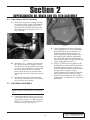
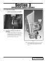
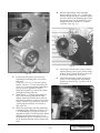
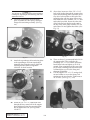
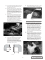
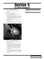
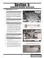
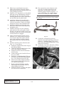
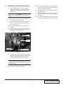
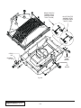
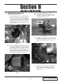
S U P E R C H A R G E R S
Owner’s Installation Guide for the
Paxton Automotive
Novi 2000 Supercharger
for the
1985 5.0L Ford Mustang
Paxton Automotive . 1300 Beacon Place . Oxnard CA 93033
805 604-1336 . FAX (805) 604-1337
DP/N: 4PFX020-020 v1.1
04/24/06
FOREWORD
T
his manual provides information on the installation, maintenance and service of the Paxton supercharger kit expressly
designed for the 1985 5.0 Ford Mustang Contact Paxton
Automotive Corporation for any additional information regarding
this kit and any of these modifications at (805) 604-1336 8:00am4:30pm PST.
An understanding of the information contained herein will help
novices, as well as experienced technicians, to correctly install and
receive the greatest possible benefit from their Paxton supercharger.
When reference is made in this manual to a brand name, number,
specific tool or technique, an equivalent product may be used in
place of the item mentioned. All information, illustrations and specifications contained herein are based on the latest product information
available at the time of this publication. All rights reserved to make
changes at any time without notice.
© 2006 PAXTON AUTOMOTIVE
All rights reserved. No part of this publication may be reproduced, transmitted, transcribed, or translated into
another language in any form, by any means without written permission of Paxton Automotive.
P/N: 4PFX020-020
©2006 Paxton Automotive
All Rights Reserved, Intl. Copr. Secured
24APR06 v1.1 MusGT(4PFX..020 v1.1)
ii
TABLE OF CONTENTS
FOREWORD . . . . . . . . . . . . . . . . . . . . . . . . . . . . . . . . . . . . . . . . . . . . . . . . . . . . . . . . . . .ii
TABLE OF CONTENTS . . . . . . . . . . . . . . . . . . . . . . . . . . . . . . . . . . . . . . . . . . . . . . . . .iii
IMPORTANT NOTE . . . . . . . . . . . . . . . . . . . . . . . . . . . . . . . . . . . . . . . . . . . . . . . . . . . .iv
TOOL & SUPPLY REQUIREMENTS . . . . . . . . . . . . . . . . . . . . . . . . . . . . . . . . . . . . . .v
PARTS LIST (1985 Ford 5.0L Mustang) . . . . . . . . . . . . . . . . . . . . . . . . . . . . . . . . . . . . .vii
1.
PREPARATION AND REMOVAL . . . . . . . . . . . . . . . . . . . . . . . . . . . . . . . .1-1
1.1
2.
3.
4.
SUPERCHARGER OIL DRAIN AND OIL FEED ASSEMBLY . . . . . . . . . .2-1
2.1
SUPERCHARGER OIL FEED ASSEMBLY . . . . . . . . . . . . . . . . . . . . . . . . . .2-1
2.2
SUPERCHARGER OIL DRAIN ASSEMBLY . . . . . . . . . . . . . . . . . . . . . . . .2-1
SUPERCHARGER BRACKET ASSEMBLY AND MOUNTING . . . . . . . . . .3-1
3.1
SUPERCHARGER BRACKET ASSEMBLY . . . . . . . . . . . . . . . . . . . . . . . . .3-1
3.2
CRANK PULLEY ASSEMBLY . . . . . . . . . . . . . . . . . . . . . . . . . . . . . . . . . . .3-1
FUEL PUMP REPLACEMENT . . . . . . . . . . . . . . . . . . . . . . . . . . . . . . . . . .4-1
4.1
5.
6.
5.1
CARBURETOR ENCLOSURE INSTALLATION . . . . . . . . . . . . . . . . . . . . .5-1
5.2
THROTTLE CABLE INSTALLATION . . . . . . . . . . . . . . . . . . . . . . . . . . . . .5-3
AIR INLET INSTALLATION . . . . . . . . . . . . . . . . . . . . . . . . . . . . . . . . . . . .6-1
AIR INLET INSTALLATION (On Passenger’s Side) . . . . . . . . . . . . . . . . . . .6-1
SUPERCHARGER DISCHARGE . . . . . . . . . . . . . . . . . . . . . . . . . . . . . . . . .7-1
7.1
8.
FUEL PUMP REPLACEMENT . . . . . . . . . . . . . . . . . . . . . . . . . . . . . . . . . . .4-1
CARBURETOR ENCLOSURE INSTALLATION . . . . . . . . . . . . . . . . . . . . .5-1
6.1
7.
PREPARATION AND REMOVAL . . . . . . . . . . . . . . . . . . . . . . . . . . . . . . . . .1-1
SUPERCHARGER DISCHARGE . . . . . . . . . . . . . . . . . . . . . . . . . . . . . . . . .7-1
FINAL CHECK OUT AND START UP . . . . . . . . . . . . . . . . . . . . . . . . . . . . .8-1
8.1
INSPECT THE FOLLOWING . . . . . . . . . . . . . . . . . . . . . . . . . . . . . . . . . . . .8-1
8.2
PERFORM THE FOLLOWING . . . . . . . . . . . . . . . . . . . . . . . . . . . . . . . . . . .8-1
8.3
CHECK FOR THE FOLLOWING . . . . . . . . . . . . . . . . . . . . . . . . . . . . . . . . .8-1
APPENDIX . . . . . . . . . . . . . . . . . . . . . . . . . . . . . . . . . . . . . . . . . . . . . . . . . . . . .A-1
1016611 Asy, Mounting Bracket 5.0 Novi 2000 . . . . . . . . . . . . . . . . . . . . . . . . . . .A-2
1016710 Asy, Crank Pulley 86-93 5.0 Novi 2000 . . . . . . . . . . . . . . . . . . . . . . . . . .A-3
iii
P/N: 4PFX020-020
©2006 Paxton Automotive
All Rights Reserved, Intl. Copr. Secured
24APR06 v1.1 MusGT(4PFX..020 v1.1)
IMPORTANT NOTE
T
his kit will require the purchase of a 4150 based
Holley or Demon carburetor with mechanical secondaries.
P/N: 4PFX020-020
©2006 Paxton Automotive
All Rights Reserved, Intl. Copr. Secured
24APR06 v1.1 MusGT(4PFX..020 v1.1)
iv
1985 Ford Mustang
Carbureted System
Installation Instructions
PLEASE READ CAREFULLY
This kit should only be installed by qualified mechanics. It is imperative that the correct air/fuel mixture be maintained at all times.
This Kit is to be supplied to competent engine tuners for their
completion by the addition of, and tuning of, an appropriate
carburetor unit.
This product is intended for use on healthy, well maintained engines.
Installation on a worn-out or damaged engine is not recommended
and may result in failure of the engine.
Paxton Automotive is not responsible for engine damage.
Installation on new engines will not harm or adversely affect the
break-in period so long as factory break-in procedures are followed.
This kit is not smog legal for on-highway use.
For best performance and continued durability, please take note of the
following key points:
1. Use only premium grade fuel 91 octane or higher (R+M/2).
2. The engine must have stock or lower than stock compression ratio.
3. If the engine has been modified in any way, check with Paxton prior to
using this product.
4. Always listen for any sign of detonation (pinging) and discontinue hard
use (no boost) until problem is resolved.
5. Perform an oil and filter change upon completion of this installation and
prior to operating the vehicle. Thereafter, always use a high grade SF
rated engine oil or a high quality synthetic, and change the oil and filter
every 3000 miles.
TOOL AND SUPPLY REQUIREMENTS:
• Oil Filter, and Wrench
• Factory Repair Manual
• 3/8" Drive and Socket Set: SAE and Metric
• 1/2" Drive and Socket Set: SAE and Metric
• Open End Wrenches: SAE and Metric
• Center Punch
• SF Rated Quality Engine Oil
• Loctite Sealer #RC-609
• Heavy Grease
• Silicone Sealer
• Teflon Paste Sealant
• TAP, 3/8-18 NPT
v
P/N: 4PFX020-020
©2006 Paxton Automotive
All Rights Reserved, Intl. Copr. Secured
24APR06 v1.1 MusGT(4PFX..020 v1.1)
N
ever rely solely on a hydraulic lift, when
working under a vehicle. Always use
approved jackstands to support the vehicle
and place them under the manufactures recommended lift points.
When lifting the vehicle, make sure it is on a level
surface, preferably concrete or asphalt. The transmission should be in “PARK” or “FIRST”, the
parking brake engaged, and the wheels blocked.
Never start the car with out first verifying that the
transmission is in neutral and the parking brake is
set.
Never remove the radiator cap while the engine is
still hot. Always wear eye protection when using
power tools such as drills, saws, grinders, etc., or
when working under a vehicle.
Never smoke, use an open flame, or have sparkproducing items around gasoline or flammable solvents. Always have a fire extinguisher rated for
chemical and electrical fires handy when working
on motor vehicles.
Run engines only in a well ventilated area.
Carbon monoxide, gasoline and solvent vapors are
colorless, and sometimes odorless. These can
asphyxiate or explode without warning.
Always disconnect at least the (-) negative or
ground terminal of the battery when doing any
electrical, fuel system, or under dash work.
We look forward to hearing from you, particularly
if you have any comments or suggestions regarding
this manual at (805) 604-1336 Paxton Automotive
Corporation, 1300 Beacon Place, Oxnard, CA
93033. E-mail Address:
[email protected]
***NOTE***
Through these procedures the word “discard” is
used periodically in relationship to items that will no
longer be utilized in conjunction with the supercharger installation. It is recommended that these items be
saved for future use should it become necessary.
P/N: 4PFX020-020
©2006 Paxton Automotive
All Rights Reserved, Intl. Copr. Secured
24APR06 v1.1 MusGT(4PFX..020 v1.1)
vi
1985 Ford 5.0L Mustang
Part No. 1001845
PARTS LIST
S U P E R C H A R G E R S
IMPORTANT: Before beginning installation, verify that all parts are included in the kit. Report any shortages or damaged
parts immediately.
PART NO.
8PM205-012
7A312-078
7A312-252
7C011-050
7F312-024
7J312-000
7F187-102
7P187-103
7P250-084
7P375-104
7P500-087
7U100-003
7U100-008
7U100-020
8M001-017
8M001-018
8PM003-051
8PM105-012
1016611
1210508
2A017-875-11
4FA011-021
4FA015-015
4FA017-021
4PFA010-031
4PFA010-044
4PFA010-054
4PFA017-011
4PFA017-071
7A250-077
7A375-100
7A375-102
7A375-124
7A375-175
7A375-200
7A375-251
7A375-300
7A375-302
7A375-625
7A375-650
7A375-675
7A375-751
7A437-175
7B500-300
7F375-016
7F500-025
7J375-044
7J438-081
7J500-001
7PA375-500
7PB500-263
1016710
2A041-568
2A046-888
4FA018-023
7A375-158
7K375-040
4FA114-023
4FA114-011
7R002-024
7000
1017400
4FA010-011
7A375-124
7A500-350
7F375-016
7F500-013
7J375-044
7J500-001
DESCRIPTION
CARB. ENCL ASY, PAXTON SBF
5/16-18 x 3/4" SHCS, S’STL
STUD, 5/16" - 2.1/2" CARB ENCLOSURE
10-32 PLUG SCREW
5/16-24 JAM NUT
5/16" FLAT WASHER-SAE
-3 BULKHEAD FITTING TO 1/4" HOSE
PLUG, -3 O-RING PORT
1/4"NPT x 1/2" x 90° BARB
PLUG, 3/8-16, BRASS, SHORT
PLUG, AN-8 O-RING PORT
O-RING 3-903
O-RING 3-908
10-32 GASKET
HOLLEY 4-BARREL BASE GASKET
GASKET, 90mm THROTTLE BODY
CARB. COVER, PAXTON MACH.
CARB. ENCL. LOWER w/BUSHING, SBF
ASY, MTG BRKT, 5.0 N2K
ASY, PULLEY SMOOTH FACE
SPACER, .875"OD x 1.482" LONG
MOUNTING BRACKET, S/C
ALTERNATOR STAY - PLATED
SPACER, SMOG PUMP
BRACKET, IDLER ADJUST SCREW
PLATE, REAR S/C MTG, NOVI 2K
PLATE, FRONT S/C MTG BRACKET, NOVI
COLLAR, 10-RIB PLY, NOVI
SPACER, BRACKET, DUAL 1.482
1/4-20 x .75" FLAT ALLEN GR5
3/8-16 x G5 HHCS, PLT
3/8-16 x 1" FHCS, ZINC, PLT
3/8-16 x 1-1/4" HHCS, G5, PLATE
3/8-16 x 1-3/4 HXHD GR5 PLT
3/8-16 x 2" HXHD GR5 PLTD
3/8-16 x 2-1/2" FLAT SHCS
3/8-16 x 3" HXCS GP5 P
3/8-16 x 3.0 FLAT HD PLATED
3/8-16 x 6-1/4" HXHD
3/8-16 x 6-1/2" HX GR5 ZINC
3/8-16 x 6.75" HXHD GR5 ZINC
3/8-16 x 7.5" HXHD GR8 ZINC
7/16-14 x 1.75 HXHD ZINC PLT
1/2-20 x 3.00" HXHD GR5 ZINC
3/8-16 HX NUT
1/2-20 HEX NUT PLATED GR5
3/8"SAE WASHER PLATED
7/16"SAE WASHER, PLATED
WASHER, 1/2"ID x 1.12"OD
SCREW, IDLER ADJUST, 5.00"
ARBOR, S/C TENS PLY, 5.0 N2K
ASY, CRANK PULLEY
BELT, DAYCO 5100568 10-RIB
BELT, 6-RIB x 88.82" EFFECT. LE
4.75/6.87" 10-GRV CRANK PULLEY
3/8-16 x 1.5" SHCS GR8 PLTD
3/8"AN960 FLAT WASHER PLATED
RADIATOR HOSE ASY
RADIATOR PIPE POLISHED
#24 SAE TYPE “F” SS HOSE CLAMP
INSPECTOR NUMBER
TENSIONER, BELT, KIT
TENSIONER MTNG. BRACKET MACH
3/8-16 x 1-1/4" HHCS, G5, PLATE
1/2-13 x 3-1/2" CARRIAGE
3/8-16 HEX NUT
1/2-13 HEX NUT
3/8"SAE WASHER, PLTD
WASHER, 1/2"ID x 1.12"OD
QTY.
PART NUMBER
1
16
4
1
4
4
3
1
1
3
3
4
3
1
2
1
1
1
1
2
4
1
1
1
1
1
1
2
1
2
2
3
4
1
1
1
3
2
1
1
1
1
1
1
2
2
17
2
3
1
1
1
1
1
1
4
4
1
1
2
0
1
1
2
1
1
1
1
1
4FA130-036
7U030-036
7P375-017
7R001-008
70000
1016420
4PFX101-001
7P125-016
7P250-043
7P250-047
7P250-141
7P500-083
7P500-084
7P500-085
7P500-086
7P500-087
7P500-089
7P500-377
7R001-006
7U030-046
7U032-016
7U037-030
7U100-008
8F001-120
8H040-020
1017300
4PFA012-101
7P375-075
7R002-010
7U038-030
7U038-000
4PFX130-351
7P125-004
7P250-034
7P250-031
7U250-090-320
7U100-055
4PFX212-050
7PS400-200
7R002-064
4PFX012-051
7U035-001
7R002-052
4H110-060
7PS375-200
7R002-056
4FA012-012
8H040-030
7U033-000
7P250-048
7P250-047
7U030-046
7P375-075
7R002-010
7E010-049
4PFX212-060
4PFX012-021
7PS300-300
7PS350-301
7R002-044
7R002-052
7R002-016
8D001-001
7U034-016
7P750-102
8M003-041
7U030-046
vii
DESCRIPTION
OIL DRAIN ASY
1/2" OIL DRAIN HOSE
3/8"NPT x 1.2" BEADED HOSE BARB
#8 STNL HOSE CLAMP
INSPECTOR NUMBER
S/C ASY, 5.0 CARB. SERP N2K CUR
FUEL PUMP ASY, SBF CARB MECH.
1/.8"NPT PLUG
1/4"NPT x 5/16" BARB
1.4"NPT x 3/8" BARB x 90°
-6 JIC PUSH ON HOSE END, 90°
-8 HOSE END STR, AL PUSH-ON
MAKE JIC TEE, -8, -6, -6
FTG, BULKHEAD -8 w/o RING
-8 HOSE END, PUSHLOC 120°
PLUG, AN-8 O-RING PORT
NUT, -8 BULKHEAD BLACK
-8 JIC MAKE ORB TO -6 MAKE FLA
#6 STNLS HOSE CLAMP, NARROW
5/32" VACUUM LINE
3/8" EFI FUEL HOSE, HI-PSR
-8 USCG FUEL HOSE, PUSH-ON
O-RING 3-908
FUEL PUMP, SBF MECH, 120 GPH, 6-PSI
FUEL FILTER, INLINE 3/8"
ASY, SMOG PUMP MOD.
MACH, SMOG PUMP ELBOW
3/4" HOSE BARB UNION, BRASS
#10 SAE TYPE “F” SS HOSE CLAMP
1/4" VACUUM HOSE
3/4" HEATER HOSE
OIL FEED ASY, SBF, '69 351
1/8"NPT x 90° x -4 JIC FTG STL
1/4"NPT x 1/4"NPT STREET TEE
1/4"NPT x -4 JIC FLARE FTG STL
OIL FEED HOSE, 32" -4 x 90°
TIE-WRAP, 7.5" NYLON
ASY, AIR INTAKE 5.0 CARB SERP.
SLEEVE, BLACK 4"OD x 2.0"
#64 SAE TYPE “F” SS HOSE CLAMP
ELBOW, 90° MOD CAST 4" x 3.5" w/HOL
3-1/2" FLEX HOSE
#52 SAE TYPE “F” SS HOSE CLAMP
FLANGE ASY, AIR BOX S2000
SLEEVE, BLACK Ø3.75" x 2.0"L
#56 SAE TYPE “F” SS HOSE CLAMP
INTAKE ELBOW, 90° w/o BOSSES
AIR FILTER 3.5" FLG x 6"L
5/8" PCV HOSE
1/4"NPT-5/8"BARB x 90°
1/4"NPT-3/8" BARB x 90°
5/32" VACUUM LINE
3/4" HOSE BARB UNION, BRASS
#10 SAE TYPE “F” SS HOSE CLAMP
#10 x 3/4" HXHD SLF DRL SHT MTL
ASY, DISCHARGE 5.0L CARB. SERP.
MACH, DISCH TUBE, SBC CARB
SLEEVE, BLACK, 3.0"OD x 3.0"L
REDUCE, BLK 3.5-3.0 x 3.0L
#44 SAE TYPE “F” SS HOSE CLAMP
#52 SAE TYPE “F” SS HOSE CLAMP
#16 SAE TYPE “F” SS HOSE CLAMP
STD COMPRESS BYPASS VALVE
1" GS HEATER HOSE
3/4"NPT x 1" x 90° HSE FIT
MACHINE, Ø3.5" FLANGE, SATIN
5/32" VACUUM LINE
QTY.
1
2
1
2
0
1
1
1
1
1
1
1
1
1
1
1
1
1
4
4.5'
2.5'
.45'
3
1
1
1
1
1
4
1'
.30'
1
1
1
1
1
2
1
1
2
1
1'
2
1
1
2
1
1
2'
1
1
3.5'
1
2
4
1
1
1
1
3
1
4
1
1'
1
1
1
P/N: 4PFX020-020
©2006 Paxton Automotive
All Rights Reserved, Intl. Copr. Secured
24APR06 v1.1 MusGT(4PFX..020 v1.1)
1985 Ford 5.0L Mustang
Part No. 1001845
PARTS LIST
S U P E R C H A R G E R S
IMPORTANT: Before beginning installation, verify that all parts are included in the kit. Report any shortages or damaged
parts immediately.
PART NO.
8M110-085
7P375-045
7U031-016
4PFA017-051
7U313-250
7J312-000
7L312-000
7F312-021
5W013-000R
5W001-029
5W001-008
7A375-100
7F312-017
7J375-044
4GF055-010
7U313-300
8M001-019
8M017-021
7U313-300
8M001-019
8M017-021
8M110-120
88M010-120
8M010-130
7P375-046
8M110-080
8M001-060
8M010-170
8M010-081
8M010-190
2A017-750-03
2A017-032
7C010-052
7C010-077
7C010-187
7C010-188
7F010-026
7J010-001
7J010-687
8M010-040
8M010-050
8M010-090
8M010-140
7P375-104
4PFX020-020
008575
3863515
DESCRIPTION
ASY, SUPPORT 5.0"L CARB SERP
3/8"NPT M/F x 45° STREET ELBOW
5/16" PCV/VAC RUBBER HOSE
SPACER, FAN .510" PILOT NOVI
STUD, 5/16-24/24 x 2.5"4
5/16" FLAT WASHER, SAE
5/16" SPLIT (LCK) WASHER
5/16-24 NUT
1/0 RED BATTERY CABLE
LUG END TERMINALS 1/0
3/4" HEAT-SHRINK TUBING
3/8-16 x 1" GS HHCS, PLT
5/16-18 NYLOCK NUT
3/8" SAE WASHER, PLTD
WASHER, RESERVOIR GM TPI
STUD, 5/16-18/24 x 3.0" LG
GASKET, 4BRRL CARB. w/EGR FORD
SPACER, CARB. w/EGR BLK OFF
STUD, 5/16-18/24 x 3.0"LG
GASKET, 4BRRL CARB. w/EGR
SPACER, CARB. w/EGR BLK OFF
DEMON PLT BWL LINE ASY w/FTGS
FUEL LINE, SS FRONT DEMON
FUEL LINE, SS REAR DEMON
FTG, -6 TO 9/16-24 BG ADAPTER
ASY, THROTTLE, LINK '85 MUS
CABLE, THROTTLE
BRKT, CHVY THROTTLE CABLE
RETAINER, THROTTLE SPRING
BRKT, THROTTLE RETURN SPRING
SPACER, .750"OD x .130" LONG
SPACER, CARB. ENCLOSURE
10-24 x 1/2" BUTTON-HEAD SCREW
10-24 x 3/4" BUTTON-HEAD CAP SCREW
ROD END, 3/16", RH THREAD, w/NUT
ROD END, 3/16", LH THREAD, w/NUT
NUT, THROTTLE
#10 FLAT WASHER
WASHER, THROTTLE ENCLOSURE
THROTTLE ARM-INNER ENCLOSURE
THROTTLE SHAFT-ENCLOSURE
SPRING, THROTTLE ENCLOSURE
SHAFT, 5/16" HEX
PLUG, 3/8-16, BRASS, SHORT
MANUAL, 5.0 MUS. CR. SERP N2K
S/C STRT INFO PKG ASY PAXT
DECAL, PAXTON COLOR 9" x 3"
P/N: 4PFX020-020
©2006 Paxton Automotive
All Rights Reserved, Intl. Copr. Secured
24APR06 v1.1 MusGT(4PFX..020 v1.1)
QTY.
PART NUMBER
1
1
2'
2
1
4
4
4
5'
2
.33'
2
2
4
1
4
1
1
4
1
1
1
1
1
2
1
1
1
2
1
1
1
3
2
1
1
1
8
1
2
1
1
1
1
1
1
1
viii
DESCRIPTION
QTY.
Section 1
PREPARATION AND REMOVAL
Disconnect all vacuum, pcv, and egr lines
from the carb. Labeling each lines function
will help to reinstall to their correct positions later.
F. Remove the four retaining nuts and washer
securing the carburetor to the manifold.
Remove the carburetor, EGR plate, and four
studs from the manifold. Discard these
items.
G. Remove the Thermal Vacuum Switch at the
rear of the manifold. Using the supplied 45º
brass street elbow, reinstall the switch pointing to the passenger side rear of the vehicle.
Reconnect the thermal switch plug. This will
allow clearance for the carburetor enclosure.
(See Figs. 1-c, 1-d.)
E.
*** NOTE ***
If vehicle has gone more than 10,000 miles since it’s
last service. It is recommended that new spark plugs
(no platinum) be installed and that the ignition timing
be set to 6-8° initial uniess using an aftermarket timing box such as the MSD 6AL-BTM. The complete
ignition system should be in good working condition
before beginning installation. IE. distributor cap and
rotor, spark plug wires, etc.
1.1
Preparation and Removal.
A. Disconnect the battery cables; remove battery hold down, battery, and battery mounting tray. Set these aside to reinstall later.
B. Remove the complete air cleaner assembly,
including the two plastic inlet Ducts located
in the inner fender wells (driver & passenger
sides). (See Fig. 1-a.)
*** NOTE ***
Use pipe sealant on the threads of both the fitting
and the switch.
THERMAL VACUUM
SWITCH
Fig. 1-a
C. Disconnect the electric choke wire from the
carb. and cut at the alternator harness.
D. Disconnect the fuel line from the carb.
Remove the throttle cable and bracket from
the car and discard. (See Fig. 1-b.)
Fig. 1-c
Fig. 1-d
Fig. 1-b
1-1
P/N: 4PFX020-020
©2006 Paxton Automotive
All Rights Reserved, Intl. Copr. Secured
24APR06 v1.1 MusGT(4PFX..020 v1.1)
H. Disconnect the slide connection plug on the
coil. Remove the coil and coil bracket from
the manifold. Reinstall the coil in it’s original bracket to the A/C bracket bolt. (See Fig.
1-e.)
STARTER SOLENOID
IN NEW LOCATION
Fig. 1-g
The ignition switch wire (and any other
wires drawing power from the solenoid) will
need to be extended to the new location.
K. Relocate the battery tray to the driver’s side.
Use the two 3/8" x 1" bolts, washers, and
nuts provided to secure the tray to the
engine compartment. Re-install the battery
and factory battery hold down. The battery
ground cable should be grounded to the
engine block. The battery positive cable is
reconnected to the starter solenoid. The
starter cable will need to be replaced with
the longer cable provided to reach the solenoids new location. Route and secure away
from heat and moving parts.
L. Locate the steel vacuum tube near the drivers side valve cover. Using the supplied
5/16" x 24" rubber hose, connect this to the
vacuum tree on the firewall. Route as shown
or for best possible carburetor linkage clearance. (See Fig. 1-h.)
Fig. 1-e
Split the wire loom to gain the necessary
wire length to reach the new coil location.
Reconnect the slide connector to the coil. (If
enough length can not be obtained use the
supplied wire and butt connectors to lengthen.)
*** NOTE ***
If a longer coil wire is needed, source a universal coil
wire kit that can be used. However, this would be a
good time to replace a worn wire set.
I.
On the passenger side of the A/C condenser,
remove the A/C line support bracket and discard. (See Fig. 1-f.)
STEEL
VACUUM TUBE
A/C LINE
SUPPORT BRACKET
Fig. 1-h
Fig. 1-f
J.
M. Thoroughly clean the intake manifold carburetor flange. Thread the supplied (4) carburetor studs into the intake manifold. And
install one of the supplied gaskets.
Relocate the starter solenoid to the driver’s
side just in front of the shock tower. (See
Fig. 1-g.)
P/N: 4PFX020-020
©2006 Paxton Automotive
All Rights Reserved, Intl. Copr. Secured
24APR06 v1.1 MusGT(4PFX..020 v1.1)
1-2
N. Loosen the petcock at the bottom of the
radiator and drain approximately one gallon
of coolant into a drain pan. (Save fluid for
re-use.)
O. Disconnect the overflow hose from the neck
of the radiator. Remove the coolant bottle
and discard.
P Using a 7/16" combination wrench, loosen
the four bolts that are securing the fan to the
water pump. With an18mm combination
wrench release the tension on the belt tensioner and remove the factory drive belt.
Now remove the four bolts that are securing
the fan to the water pump. (See Figs. 1-i.)
Fig. 1-j
R. Using a 7/16" wrench or socket, remove the
two sheet metal screws securing the fan
shroud to the radiator core support and
remove the fan shroud, fan clutch and fan
from the vehicle. (See Fig. 1-k.)
Fig. 1-k
Fig. 1-i
Q. Using a 10mm socket & ratchet or screw
driver, loosen the clamps and remove the
upper radiator hose from the vehicle. Save
for re-use. (See Fig. 1-j.)
1-3
P/N: 4PFX020-020
©2006 Paxton Automotive
All Rights Reserved, Intl. Copr. Secured
24APR06 v1.1 MusGT(4PFX..020 v1.1)
S.
Using a 19mm wrench, loosen the bolt
securing the accessory drive belt tensioner to
the factory bracket and remove the tensioner
from the bracket. Set aside to be used in a
later step of the installation. (See Fig. 1-l.)
W. For supercharger clearance, it is necessary to
replace the stock 90° hose port on the smog
pump with the smaller piece provided.
Locate the supplied assembly and replace
the stock piece now. (See Fig. 1-n.)
Fig. 1-l
T.
Unplug the electrical connection at the alternator, and using a 9/16" and a 1/2" socket,
remove the alternator from the factory
bracket. (See Fig. 1-m.)
Fig. 1-n
X. Using a 9/16" socket and extension, remove
the remaining bolts securing the factory
bracket to the engine. Set the bracket aside,
this bracket will not be re-used.
Y. On the frame rail, there is an evaporator
canister. From underneath the vehicle, use a
1/2" socket and remove the two bolts securing the canister bracket to the frame rail.
Reposition the canister forward, towards the
front of the vehicle, using one of the stock
bolts. Resecure the canister to the frame rail
using the forward hole in the frame rail and
the rear hole in the bracket.
Fig. 1-m
U. Using a 5/16" nut driver, loosen the clamps
and remove the air injection hose from the
smog pump and diverter valve up next to the
valve cover. Disconnect the vacuum line
behind the smog pump and remove the hose
from the vehicle. Set aside for re-use
V. Remove the bolt at the rear of the smog
pump using a 9/16" socket and the two at
the front of the pump, remove the smog
pump from the vehicle.
P/N: 4PFX020-020
©2006 Paxton Automotive
All Rights Reserved, Intl. Copr. Secured
24APR06 v1.1 MusGT(4PFX..020 v1.1)
1-4
Z.
Remove the four factory crank pulley bolts
with a 9/16" socket and extension and
remove the pulley from the vehicle. (See
Fig. 1-o.)
Fig. 1-o
1-5
P/N: 4PFX020-020
©2006 Paxton Automotive
All Rights Reserved, Intl. Copr. Secured
24APR06 v1.1 MusGT(4PFX..020 v1.1)
This Page Left Intentionally Blank
P/N: 4PFX020-020
©2006 Paxton Automotive
All Rights Reserved, Intl. Copr. Secured
24APR06 v1.1 MusGT(4PFX..020 v1.1)
1-6
Section 2
SUPERCHARGER OIL DRAIN AND OIL FEED ASSEMBLY
2.1
Supercharger Oil Feed Assembly
A. Remove the oil pressure sending unit located near the oil filter. Apply clean motor oil
to the threads of the supplied street TEE.
Install the TEE with the branch facing the
front of the engine, referring to Fig. 3.1-a
for positioning.
Fig. 2-b
Upon completion of the drilled pilot hole,
insert a rigid thin piece of wire through the
drilled pilot hole to ensure that there is a
straight shot for the punch to go into. If
there is anything blocking the path, rotate
the engine by hand using the appropriate
size socket and ratchet, to rotate the crankshaft. Insert the punch into the pilot hole and
evenly enlarge the hole to 9/16".
C. Using a 3/8"NPT tap (not supplied) tap the
punched hole to accommodate the threaded
brass fitting. Before tapping, coat the tap
with thick lithium grease to retain the metal
shavings while you tap the oil pan.
Upon completion of the tapped oil pan hole,
coat the threaded end of the brass fitting
with silicone and thread into the oil pan, be
cautious not to over tighten or to strip the oil
pan threads.
B.
Fig. 2-a
B. Install the 1/8" x –4 fitting in the branch of
the TEE and connect the supplied oil feed
line. Route the line up toward the passenger
side valve cover behind the accessory brackets. Secure line away from any moving
parts. Cap the line to prevent debris from
entering until the line is connected in a later
step.
C. Reinstall the factory oil pressure sending
unit in to the end of the street TEE, and connect the factory wire harness.
2.2
OIL DRAIN ASSEMBLY
***IMPORTANT***
Before continuing, drain the motor oil from the vehicle.
A. From underneath the vehicle you will need
to drill a pilot hole in the oil pan on the passenger side by using a 1/8" drill bit approximately 1-1/2" from the top and 2" from the
front of the oil pan. (See Fig. 2-b.)
2-1
P/N: 4PFX020-020
©2006 Paxton Automotive
All Rights Reserved, Intl. Copr. Secured
24APR06 v1.1 MusGT(4PFX..020 v1.1)
This Page Left Intentionally Blank
P/N: 4PFX020-020
©2006 Paxton Automotive
All Rights Reserved, Intl. Copr. Secured
24APR06 v1.1 MusGT(4PFX..020 v1.1)
2-2
Section 3
SUPERCHARGER BRACKET ASSEMBLY
3.1
Crank Pulley Assembly
A. With the 4 supplied bolts 3/8 x 1 in length
install the new crank pulley and torque the
bolts to 25-28ft pounds. (See Fig. 3-a.)
PAXTON
SUPPLIED
90° FITTING
Fig. 3-a
3.2
Supercharger Bracket Assembly and
Mounting
A. Locate the supercharger mounting bracket
assembly #101661 and the cast supercharger
mounting bracket. Also locate the 3/8" x
6.5" long bolt, 3/8" x 6.25" bolt, the 3/8" x
2", and insert them into the rear of the cast
mounting bracket. (See Fig.3-b.)
ALTERNATOR
STAY
Fig. 3-b
B. Attach the alternator stay bracket to the boss
on the bottom of the smog pump using the
3/8" x 1" bolt and washer provided. (See
Fig. 3-c.)
3-1
P/N: 4PFX020-020
©2006 Paxton Automotive
All Rights Reserved, Intl. Copr. Secured
24APR06 v1.1 MusGT(4PFX..020 v1.1)
SPACER LOCATION
Fig. 3-c
*** NOTE ***
Leave these bolts loose. All bolts will be tightened
once the bracket is installed on the motor.
C. With the smog pump and the alternator as an
assembly. Slide them over the bolts previously installed into the cast bracket.
Locate the small spacer that will go between
the smog pump and the main supercharger
mounting bracket. Install this spacer onto
the upper-most bolt of the smog pump. (See
Fig. 3-d)
Fig. 3-d
D. Install the large supercharger mounting plate
over the bolts that were previously installed
through the cast bracket. (See Fig. 3-e.)
P/N: 4PFX020-020
©2006 Paxton Automotive
All Rights Reserved, Intl. Copr. Secured
24APR06 v1.1 MusGT(4PFX..020 v1.1)
3-2
H. Bolt the Supercharger to the mounting
bracket with one of the 3/8" x 1" bolts and
washers through the upper most hole and the
two lower holes in the mounting plate. Place
the support plate over the front of the supercharger and secure with the 3/8" countersunk bolts. (See Fig. 3-f.)
Fig. 3-f
I.
Fig. 3-e
Locate nuts and washers and secure the
supercharger mounting plate. Leave these
nuts loose.
Locate the 7/16-14 1.75" bolt and washer
and the 3/8-16 x 1.75" bolt and washer, the
3/8-16 x 6.75" bolt and washer. Install these
bolts as noted in Appendix #1016611.
Install this assembly as a unit to the engine
and tighten all bolts and nuts.
F. Install the 90° x -4 fitting using engine oil
only on the threads going into the supercharger. Attach the oil drain hose to the fitting and route the hose so there are no kinks
or dips. See that it is routed away from hot
or sharp objects and there are no kink or
dips in the line.
G. Install the supercharger into the supercharger mounting plate using three of the 3/8-16 x
1.25" bolts and the 3/8" washers. Refer to
Appendix #1016611 for their location. When
attaching the belt tensioner plate, it is recommended that the use of anti-seize be used
on the heads and threads of the counter-sunk
bolts.
E.
J.
Connect the oil drain hose to the previously
installed fitting in the oil pan. Secure using a
#8 hose clamp. Trim for best fit so there are
no kinks or sharp bends in the hose.
Connect the previously install oil feed line
to the -4 x 90° fitting on the supercharger.
Position as shown in Fig. 3-g and secure to
the bracket.
Fig. 3-g
3-3
P/N: 4PFX020-020
©2006 Paxton Automotive
All Rights Reserved, Intl. Copr. Secured
24APR06 v1.1 MusGT(4PFX..020 v1.1)
N. Above that, insert two of the 3/8" x 3 1/4"
bolts with washers through the support plate,
spacer and mounting plate. Secure the accessory drive belt tensioner to the back of the
mounting plate with the upper of these two
bolts holes, the lower with the 3/8" x 1" bolt
and washer provided. Secure the other side
of the belt tensioner bracket to the stud at
the top of the water pump with the 3/8" nut
and washer. Do not tighten these bolts. (See
Fig. 3-j)
*** NOTE ***
You will have to route the accessory drive belt before
installing the supercharger belt tensioning plate. See
Appendix #1016710.
K. Locate the supercharger belt tensioning
plate. Assemble the idler pulley and supercharger belt tensioning assembly. (See Fig.
3-h.)
Fig. 3-j
Fig. 3-h
L.
O. There are three (3) countersunk holes left in
the support plate. They each take the
remaining 3/8" x 3 1/4" counter sunk bolts.
Install these bolts and tighten to 28-30 ft
pounds. Upon completion of this step, tighten all of the remaining bolts that have been
left hand tight, as well as the Smog and
alternator assemblies.
P Use the supplied 1/2" x 3 1/2" carriage bolt,
nut and washer to secure the factory belt
tensioner to the new bracket. Tighten nut to
28-30 ft lbs.. (See Figs. 3-j, 3-k.)
Attach the supercharger belt tensioning plate
to the supercharger and rear supercharger
mounting plate using the spacers, bolts and
washers provided. Refer to Appendix
#1016611 for their location.
Fig. 3-i
M. Install the 3/8" x 2 1/2" countersunk bolt
through the lower most hole in the support
plate and thread it into the mounting plate.
Do not tighten this bolt. (See Appendix
1016611.)
P/N: 4PFX020-020
©2006 Paxton Automotive
All Rights Reserved, Intl. Copr. Secured
24APR06 v1.1 MusGT(4PFX..020 v1.1)
Fig. 3-k
3-4
Q. Use an 18mm wrench to rotate the accessory
belt tensioner and reinstall the factory belt.
(See Appendix 1016710.)
R. Install the supercharger drive belt between
the crank pulley and the supercharger pulley.
Route the belt inside the idlers. Use a 3/8"
socket and extension and tighten the belt.
Once the belt is tensioned, tighten the nut on
the end of the adjustable idler so that it will
not back off.
S. Find the rubber air injection hose from the
diverter valve removed in an earlier step.
Shorten the hose by cutting 3" out of the
middle of the hose and 1-1/2" off the back
of the hose. Reconnect the two formed
pieces together with the sleeve and clamps
provided. Re-install the short end hose
between the diverter valve and fitting on the
side of the smog pump. (See Fig. 3-l.)
U.
PASSENGER’S
SIDE OF SHROUD
Fig. 3-n
*** NOTE ***
Only the bottom and passenger sides are trimmed.
PREFORMED
PIECES
Install the supplied water pump pulley studs
into the w/Pump flange. Slide the two supplied spacers stacked onto the studs. Reinstall the fan shroud and fan assembly into
the engine compartment. Attach the fan
assembly to the water pump. Using the supplied washers and nuts to secure it, tighten
to factory specifications. Use the factory
screws to re-install the shroud onto the radiator core support.
W. Locate the supplied radiator overflow bottle.
Using it as a template, mark the two hole
locations on the passenger’s side inner fender. Drill a 1/8" pilot hole for each location.
Using the supplied self-tapping screws,
secure the overflow bottle in place. Route
the supplied 5/16" x 5' rubber hose from the
radiator fill port to the bottom of the overflow bottle. Refill the cooling system with
coolant previously drained. (See Fig. 3-o.)
V.
Fig. 3-l
T.
Trim the fan shroud as seen in Fig. 3-n. This
is easiest with a pneumatic cut-off wheel.
Cut the upper radiator hose. Re-install the
longer piece on the thermostat housing
angled forward. Install the shorter 90º
degree piece on the radiator angled to the
side. Install the stainless tube between the
two pieces of hose and secure with the supplied clamps. (See Fig. 3-m.)
2"
3"
2"
3"
Fig. 3-m
Fig. 3-o
3-5
P/N: 4PFX020-020
©2006 Paxton Automotive
All Rights Reserved, Intl. Copr. Secured
24APR06 v1.1 MusGT(4PFX..020 v1.1)
This Page Left Intentionally Blank
P/N: 4PFX020-020
©2006 Paxton Automotive
All Rights Reserved, Intl. Copr. Secured
24APR06 v1.1 MusGT(4PFX..020 v1.1)
3-6
Section 4
FUEL PUMP REPLACEMENT
4.1
FUEL PUMP REPLACEMENT
*** NOTE ***
If the stock fuel pump has a return line to the fuel
tank, cap this line or remove it from the vehicle and
cap the tank.
A. Disconnect the fuel lines from the fuel
pump.
B. Remove the fuel pump.
C. Install the supplied fuel pump and gasket
using the stock hardware.
D. Attach the supplied vacuum hose to the barb
fitting on the fuel pump. The other end of
this hose will be connected to the carburetor
enclosure in a later step.
E. Install the 1/4" NPT to 3/8" barb 90º in the
fuel pump outlet.
F. Install the 1/4" NPT to 5/16" barb straight in
the fuel inlet. (See Fig. 4-f.)
Fig. 4-f / View from below the engine
G. Re-attach the fuel supply line using the factory hose clamp.
H. Attach the supplied 3/8" fuel line from the
fuel pump outlet to the supplied fuel filter.
Attach a piece of 3/8" fuel line to the filterout and then route up to where the carburetor enclosure will be installed. Install and
tighten the supplied hose clamps on all connections.
I. Install the supplied –6 90º hose end into the
open end of the 3/8" hose where it will connect to the bulkhead fitting on the carburetor
enclosure.
4-1
P/N: 4PFX020-020
©2006 Paxton Automotive
All Rights Reserved, Intl. Copr. Secured
24APR06 v1.1 MusGT(4PFX..020 v1.1)
This Page Left Intentionally Blank
P/N: 4PFX020-020
©2006 Paxton Automotive
All Rights Reserved, Intl. Copr. Secured
24APR06 v1.1 MusGT(4PFX..020 v1.1)
4-2
Section 5
CARBURETOR ENCLOSURE INSTALLATION
5.1
CARBURETOR ENCLOSURE
INSTALLATION
STANDARD
CARBURETOR GASKET
*** NOTE ***
Due to the many possible configurations of intake
manifolds (with regard to carburetor flange height) a
carburetor spacer may be required to obtain the necessary height for proper supercharger and discharge
duct alignment. If hood interference is a problem, a
lower profile intake manifold may be required. This
kit was designed to work with the stock manifold for
this application
*** NOTE ***
If possible, connect the PCV valve hose to a vacuum
source on the intake manifold. If no source is available, connect to the 1/4” NPT hole in back of the
enclosure.
.50" SPACER
FACTORY EGR
GASKET
Fig. 5-a
A. Make sure the carburetor-mounting surface
is clean and dry. Locate the 8M110-085 support assembly. Replace the factory carburetor studs using the 3.0" long studs (7U313300) provided. Place the manifold to EGR
spacer gasket (8M001-019) (gasket has provision for EGR) onto the manifold. Slide the
supplied .50" thick EGR eliminating spacer
over the studs until it seats flat on the surface. Install one of the provided carburetor
gaskets (8M001-017) onto the spacer previously installed. (See Fig. 5-a.)
Fig. 5-b
*** NOTE ***
The carburetor spacer provided is for use with the
factory intake manifold and is designed to block off
the EGR passage. After market intakes may not
require the spacer to be used.
B. Install the lower part of the carburetor enclosure over the studs until it sits flat on the
intake manifold.
C. Install the other carburetor gasket over the
studs until it sits flat on the carburetor enclosure carburetor mounting surface.
D. Install the throttle nut through the large hole
on the outside of the throttle arm. Using a
10-24 cap screw inserted through a rod end
and the #10 fender washer, thread into the
throttle nut and tighten. (See Figs. 5-b, 5-c.)
Fig. 5-c
E.
Install two of the brass plugs in each side of
the carburetor enclosure. (See Fig. 5-d.)
Fig. 5-d
5-1
P/N: 4PFX020-020
©2006 Paxton Automotive
All Rights Reserved, Intl. Copr. Secured
24APR06 v1.1 MusGT(4PFX..020 v1.1)
M. Hose connections to the carburetor enclosure will vary widely depending on the
application. All holes that are not used
should be plugged with the supplied -3, -8
and 1/4"NPT plugs. The supplied fittings
and lines were meant for a stock vehicle.
With the one armed throttle arm on the
inside of the enclosure, insert the splined
shaft through the throttle bushing on the side
of the carburetor enclosure.
G. Install the .130" long spacer over the splined
shaft until it rests flat against the outside of
the enclosure. (See Fig. 5-h.) Line up the
remaining throttle arm with the inner throttle
arm and slide onto the splined shaft.
F.
*** NOTE ***
All -3 and -8 fittings should have an O-ring installed
before using.
H. Tighten the clamp screws on both of the
throttle arms. Rotate the throttle linkage to
verify free movement. If drag is felt, adjust
the distance between the two throttle arms.
I. Install the remaining rod end on the outer
hole on the inside of the inside throttle arm
and tighten screw.
J. Install the carburetor over the carburetor
studs until it sits flat on the gasket. Install
the four 5/16" nuts and washers on the studs
and tighten. Make sure unused vacuum ports
on the carburetor are plugged.
K. With a jam nut installed on each rod end,
install the 5/16" coupler shaft between the
two rod ends. Adjust the coupler until the
angle of the carburetor enclosure throttle
arm matches that of the carburetor throttle
arm.
L. Install the fuel lines on the carburetor (See
Figs. 5-e, 5-f.) as follows:
1. Install the -8 bulkhead nut and O-ring on
the bulkhead fitting.
2. Thread the bulkhead fitting into the front
hole in the carburetor enclosure.
3. Install the fuel lines into the carburetor
bowls loosely.
4. Connect the free end of each fuel line to
the -8/-6/-6 TEE.
5. Install the -8 straight hosebarb fitting on
the inside of the bulkhead fitting. Install
the -8 120° fitting on top of the TEE.
6. Measure and cut the supplied pushlock
hose so that it will fit well between the
two installed barb fitttings.
7. Remove the barbed fittings, coat the
barbs with grease, and fully insert the
barbed fittings in the hose.
8. Install the fuel hose assembly and tighten
all of the fuel line connections.
P/N: 4PFX020-020
©2006 Paxton Automotive
All Rights Reserved, Intl. Copr. Secured
24APR06 v1.1 MusGT(4PFX..020 v1.1)
Fig. 5-e
N. Connect the vacuum hose previously
attached to the small barb fitting on the fuel
pump to a -3 bulkhead fitting in the enclosure. Leave the bulkhead fitting open on the
inside of the enclosure.
O. Connect the -6 90° hose end to the -6 fitting
on the bulkhead fitting. (See Fig. 5-f.)
Fig. 5-f
5-2
5.2
H. Check for full throttle by pressing the accelerator to the floor and verifying that the carburetor butterflies open fully.
I. If possible, pressurize the fuel system and
check for leaks.
J. Using the supplied 5/16" cap screws, install
the top cover on the enclosure and tighten
the screws.
K. Use the supplied hardware to plug any open
holes in the carburetor enclosure and cover.
THROTTLE CABLE INSTALLATION
A. Using a small square file, file two grooves
in the firewall where the throttle cable goes
through. Reference the cable housing for
dimensions.
*** NOTE ***
The grooves should be in the 12 and 6 o:clock positions.
B. Install the cable in the firewall and connect
to the stock accelerator pedal.
C. Mount the throttle cable bracket to the carburetor enclosure using the supplied hardware. (See Fig. 5-g.)
D. Secure the throttle cable to the mounting
bracket.
E. Install the throttle return-spring bracket to
the linkage arm using one 10-32 x 1/2" button-head screw. (See Fig. 5-f.)
WASHER
THROTTLE
CABLE
10-32
BUTTON HEAD
VORTECH RETAINER
Fig. 5-g
F.
Connect the cable to the linkage arm using
the Vortech retainer and washer. The retainer
should go through the cable end, washer,
return-spring bracket and into the arm.
*** NOTE ***
There is a plastic sheath that nomally protects the
cable. Remove this as it may hang-up on the end of
the cable housing.
G. Install the throttle return spring.
5-3
P/N: 4PFX020-020
©2006 Paxton Automotive
All Rights Reserved, Intl. Copr. Secured
24APR06 v1.1 MusGT(4PFX..020 v1.1)
DEMON THROTTLE
ASSEMBLY SETUP
(INVERTED INNER
THROTTLE ARM)
HOLLEY THROTTLE
ASSEMBLY SETUP
(STANDARD INNER
THROTTLE ARM)
O-RING
NUT
THROTTLE
CABLE
BRACKET
BULKHEAD
FITTING
.130"
SPACER
Fig. 5-h
P/N: 4PFX020-020
©2006 Paxton Automotive
All Rights Reserved, Intl. Copr. Secured
24APR06 v1.1 MusGT(4PFX..020 v1.1)
5-4
Section 6
AIR INLET INSTALLATION
6.1
AIR INLET INSTALLATION
(on the passenger’s side)
C. Re-install the plastic inner fender.
D. Install the 1/4"NPT-5/8" barb 90° and the
1/4"NPT-3/8" barb 90° into the 4" x 3.5"
cast elbow. (See Fig. 6-d.)
A. Install the supplied 3.5" steel flanged bulkhead in the hole where the factory plactic
inlet duct was removed. Use the bulkhead as
a template mark and drill the four mounting
holes using an 1/8" drill. Attach the bulkhead using the supplied self-tapping screws.
(See Fig. 6-a.)
5/8" BARB
3/8" BARB
Fig. 6-d
E.
Using the supplied #64 hose clamps, attach
the 4"ID x 2" long sleeve and 4" x 3.5" cast
elbow to the supercharger inlet. (See Fig.
6-e.)
Fig. 6-a
B. Unscrew and pull back the passenger side
plastic inner fender to gain access to the filter location. Attach the 3.5" plastic 90° tube
to the bulkhead using the supplied 3.5" x 2"
sleeve and #56 hose clamps. Attach the air
filter to the tube and rotate assembly for best
inner fender clearance. (See Fig. 6-b.)
Fig. 6-e
F.
Using the #52 hose clamps connect the section of 3.5" flex-hose between the cast
elbow and the 3.5" steel flange bulkhead.
(See Fig. 6-e.)
Fig. 6-b
6-1
P/N: 4PFX020-020
©2006 Paxton Automotive
All Rights Reserved, Intl. Copr. Secured
24APR06 v1.1 MusGT(4PFX..020 v1.1)
J.
G. Connect the supplied length of 5/8" hose to
the previously installed 5/8" 90° fitting on
the cast elbow. Trim for best fit and attach to
the stock fitting on the valve cover. (See
Fig. 6-g.)
SUPPLIED
5/8" HOSE
Fig. 6-g
H. Connect the factory 3/8" hose with the
check valve (previously connected to factory
carburetor) to the 3/8" 90° fitting installed in
the cast inlet elbow. Route the A/C line
down under the 1" port on the cast inlet
elbow. (See Fig. 6-h.)
I. Attach a piece of the supplied 1"ID rubber
hose approximately 9.5" long to the 1" port
on the cast elbow and secure using a #16
hose clamp. Connect the by-pass valve to
the open end of hose and secure with a #16
hose clamp. Attach a piece of 1"ID rubber
hose approximately 2" long to the open end
of the by-pass valve and secure using a #16
hose clamp. (See Fig. 6-h.)
VACUUM LINE
CONNECTION
LOWER REAR
BYPASS VALVE
1" x 9.5"
RUBBER HOSE
A/C LINE
FACTORY 3/8" LINE
WITH CHECK VALVE
1" x 2" RUBBER HOSE
Fig. 6-h
P/N: 4PFX020-020
©2006 Paxton Automotive
All Rights Reserved, Intl. Copr. Secured
24APR06 v1.1 MusGT(4PFX..020 v1.1)
6-2
Connect a piece of the supplied vacuum line
to the top of the by-pass valve. Route the
line to the rear of the carburetor enclosure
and attach to the vacuum fitting previously
installed.
Section 7
SUPERCHARGER DISCHARGE
7.1
SUPERCHARGER DISCHARGE
A. Attach the 3" x 3" sleeve onto the supercharger discharge using the supplied #44
hose clamp. (See Fig. 7-a.)
Fig. 7-c
D. Using the supplied #52 hose clamp, secure
the 3.5" x 3" reducer sleeve to the 3.5" cast
flange. (See Fig. 7-d.)
Fig. 7-a
B.
Install the 3/4"NPT x 1" plastic 90° into the
cast discharge tube as seen. (See Fig. 7-b.)
Fig. 7-d
Fig. 7-b
C. Using the supplied 5/16-18 x 3/4" socket
head screws and gasket, attach the 3.5" cast
flange onto the carburetor enclosure lid.
(See Fig. 7-c.)
7-1
P/N: 4PFX020-020
©2006 Paxton Automotive
All Rights Reserved, Intl. Copr. Secured
24APR06 v1.1 MusGT(4PFX..020 v1.1)
Install the discharge tube between the supercharger discharge and carburetor enclosure
inlet and secure with the remaining #44 hose
clamps. Attach the by-pass valve to the 1" x
90° fitting on the discharge tube and secure
with a #16 hose clamp. (See Fig. 7-e.)
*** NOTE ***
Check that all clamps are tight.
Fig. 7-e
P/N: 4PFX020-020
©2006 Paxton Automotive
All Rights Reserved, Intl. Copr. Secured
24APR06 v1.1 MusGT(4PFX..020 v1.1)
7-2
Section 8
FINAL CHECK OUT AND START UP
8.3
This section covers pre-start checks and inspections, as well as initial start-up.
8.1 Inspect the following:
A.
B.
C.
D.
A. Wires, harnesses and electrical connections.
Are all items properly dressed, connected
and secured? If any electrical connections
have been dis-connected, re-connect them
before you start your vehicle.
B. Hoses, lines and fittings. Are all items properly dressed, connected and secured?
C. Fasteners, brackets, and clamps. Are all
items properly installed and tightened?
D. Fluid levels. Is the radiator coolant and the
engine oil at their proper levels? Are there
any fluid leaks?
C. Belt(s). Is the serpentine drive belt (or
accessory drive and supercharger drive belts,
depending on the requirement of your vehicle) properly installed, aligned and tensioned?
8.2
Check for the following:
Fuel leaks.
Fluid leaks.
Belt slippage.
Throttle response.
***CAUTION***
See the supercharger service manual included in
your kit for information on supercharger servicing
and maintenance, belt tightening, troubleshooting,
special tuning, and warranty information.
Now that the work is done, it’s time to enjoy
your labor of love. Take the car out on the road
and let it flex it’s muscles, but remember, the
response and performance will now be different
from that to which you have been accustomed.
Have fun!
Perform the following:
A. Re-jet the carburetor as required. Check the
ignition timing to make sure that it is properly set.
*** NOTE ***
This manual does not address specific settings for
air/fuel timing requirements. Engine tuning MUST be
performed by an experienced technician or serious
engine damage may result.
B. Check the entire fuel system for any leaks.
C. Start the car. Verify that the oil pressure is
within the normal operating range. Listen
closely. The engine should idle and sound
the same as it did before you began the
installation. Shutdown the engine, disconnect the oil feed line from the blower.
Remove the oil jet from the blower. Blow
through the oil jet to ensure there is no
blockage or foreign matter plugging it. Reinstall oil jet and oil feed line and proceed.
D. Allow the engine to come to normal operating temperatures. Bleed the cooling system
and top off as necessary.
8-1
P/N: 4PFX020-020
©2006 Paxton Automotive
All Rights Reserved, Intl. Copr. Secured
24APR06 v1.1 MusGT(4PFX..020 v1.1)
*** IMPORTANT NOTE ***
Due to tight tolerances , be very careful when
closing the hood for the first time, making sure
that there is not any interference between the
s/c and the hood of the car. By doing this you
will eliminate damaging your vehicle and/or
supercharger.
Completed Installation on a Carbureted 5.0L Ford Mustang Motor
P/N: 4PFX020-020
©2006 Paxton Automotive
All Rights Reserved, Intl. Copr. Secured
24APR06 v1.1 MusGT(4PFX..020 v1.1)
8-2
Appendix
P
lease realize that PAXTON Automotive is constantly improving the performance and look of the NOVI 2000 supercharger. Parts in your kit may appear
differently than what is pictured in this manual. This is due to photographs
taken in pre-production, a change in material costs, or an improvement in performance.
Rest assured that you have purchased to best quality kit that PAXTON Automotive
manufactures at this time. The installation of the materials will remain the same.
Appendix Part Number
Description
Page
A
1016611
Asy, Mtg Brkt 5.0L Novi 2000
A-2
B
1016710
Asy, Crank Pulley, 86-93 5.0L Novi 2000
A-3
A-1
P/N: 4PFX020-020
©2006 Paxton Automotive
All Rights Reserved, Intl. Copr. Secured
24APR06 v1.1 MusGT(4PFX..020 v1.1)
P/N: 4PFX020-020
©2006 Paxton Automotive
All Rights Reserved, Intl. Copr. Secured
24APR06 v1.1 MusGT(4PFX..020 v1.1)
A-2
18
17
17
13
25
25
10
19
17
12
11
17
19
30
A.
17
15
4
15
16
14
5
9
8
24
6
2
20
17
Part Number: 1016611
17
31
29
7
4
17
14
32
25
28
14
27
3
17
22
26
FINISH
WEIGHT
-----
-----
-----
Asy, Mounting Bracket 5.0 Novi 2000
NONE
APPR.
17
33
17
D
SCALE: 1:1.5
SIZE
1016611
DO NOT SCALE DRAWING
DWG. NO.
ASY, S/C MTG BRKT
REV.
L
SHEET 1 OF 1
86-'93 MUSTANG 5.0L w/NOVI 2000
1300 BEACON PLACE OXNARD, CA 93033
TEL: (805) 604-1336 FAX: (805) 604-1337
DESCRIPTION
MTNG BRCKT, S/C
PLATE, FRONT
PLATE, REAR
SPACER, 8.75" x 1.482"L
3/8-16 x 2 1/2" FL SHCS
IDLR SCREW
SCREW, IDLR ADJR
5/16-18 x 3/8" HHCS-SS
ARBOR, SC TENS PLY
3/8-16 x 1.0" FL SHCS
3/8-16 x 3.0" F HD
COLLAR, 10-RIB PLY, NOVI
PULLEY, IDLR SMOOTH
WASHER, 3/8"SAE PLTD
3/8-16 x 3" HXCS
3/8-16 x 1-1/4" HXHD
WASHER, 1/2"ID x 1.12"OD
1/2-20 x 3" HXHD
1/2-20 x 1.5" HHCS
3/8-16 x 7" HXHD
3/8-16 x 6.75" HXHD
3/8-16 x 1.75" HXHD
SCREW, HXHD,3/8-16UNC-2A x 6.25"LG.
SPACER, ALT BRCKT
3/8-16 x 1" HXHD
3/8-16 x 2" HXHD
7/16-14 x 1.75" HXHD
7/16"SAE WASHER
SPACER, SMOG
ALTERNATOR STAY
3/8-16 HX NUT
LABEL, ALTERNATOR DATA
3/8-16 x 6.50" HXHD
S U P E R C H A R G E R S
PART NO.
ITEM NO. QTY.
4FA011-021
1
1
4PFA010-054
2
1
4PFA010-044
3
1
4
4 2A017-875-11
7A375-251
5
1
4PFA010-031
6
1
7PA375-500
7
1
7A250-077
8
2
7PB500-263
9
1
7A375-102
10
3
7A375-302
11
2
4PFA017-011
12
2
1210508
13
2
7J375-044
14
16
7A375-300
15
3
7A375-124
16
3
7J500-001
17
3
7B500-300
18
1
7F500-025
19
2
7A375-751
20
1
7A375-675
21
1
7A375-175
22
1
7A375-625
23
1
4PFA017-071
24
1
7A375-100
25
3
7A375-200
26
1
7A437-175
27
1
7J438-081
28
1
4FA017-021
29
1
4FA015-015
30
1
7F375-016
31
2
4832500
32
1
7A375-650
33
1
23
UNLESS OTHERWISE SPECIFIED
CAD GENERATED DRAWING,
DIMENSIONS ARE IN INCHES
DO NOT MANUALLY UPDATE
TOLERANCES ARE: .XX± .01
DECIMALS:
.XXX±.005
DATE
APPROVALS
±1/2•
FRACTIONS:
DRAWN
TAP
01/27/03
ANGLES:
±1/16
ENGINEERING
--------MATERIAL
R&D
SEE PARTS LIST
---------
31
21
1
17
A-3
P/N: 4PFX020-020
©2006 Paxton Automotive
All Rights Reserved, Intl. Copr. Secured
24APR06 v1.1 MusGT(4PFX..020 v1.1)
S
PU /C
LL
EY
B.
NS
I
PU ONER
LL
EY
TE
PART OF 1016410
4
Part Number: 1016710
PART OF 1016610
OG
PU PUM
LL
EY P
SM
3
TO CRANKSHAFT
1
ITEM QTY
1
1
2
4
3
4
4
1
5
1
6
1
NONE
WEIGHT
--- LBS
-----
-----
Asy, Crank Pulley 86-93 5.0 Novi 2000
FINISH
APPR.
5
C
SCALE: NONE
SIZE
1016710
DO NOT SCALE DRAWING
DWG. NO.
ASY, CRANK PULLEY
'86-'93 MUSTANG 5.0L w/NOVI
REV.
F
SHEET 1 OF 1
1300 BEACON PLACE OXNARD, CA 93033
TEL: (805) 604-1336 FAX: (805) 604-1337
DESCRIPTION
PULLEY, CRANK 10-GRV Ø7.034 P
SCREW, 3/8-16 x 1.00" SHCS GR8
WASHER, FLAT 3/8"AN960-616
BELT, S/C DRIVE 10-GRV POLYCOG 1441mm x 35.7mm
BELT, ACCESSORY DRIVE 6-GRV MICRO-V 2525mm x 21mm
STICKER, BELT ROUTING
WE
PU R ST
MP EER
PU ING
LL
EY
PO
S U P E R C H A R G E R S
PART NUMBER
8002615
4815801
1046290
4831232
4831201
4813000
UNLESS OTHERWISE SPECIFIED
CAD GENERATED DRAWING,
DIMENSIONS ARE IN INCHES
DO NOT MANUALLY UPDATE
TOLERANCES ARE: .XX± .01
DECIMALS:
.XXX±.005
DATE
APPROVALS
±1/2•
FRACTIONS:
DRAWN
CFB
8/14/01
ANGLES:
±1/16
ENGINEERING
--------MATERIAL
R&D
SEE PARTS LIST
---------
2
AL
PU T
LL
EY
CO A/C
MP
RE
PU SSOR
LL
EY
WA
TE
R
PU PUM
LL
EY P
CE
TE SSOR
NS
IO Y
PU NER
LL
EY
AC
S U P E R C H A R G E R S
Paxton Automotive . 1300 Beacon Place . Oxnard CA 93033
805 604-1336 . FAX (805) 604-1337
DP/N: 4PFX020-020 v1.1
04/24/06