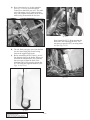
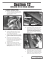
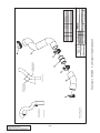
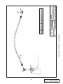
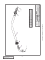
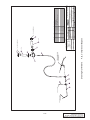
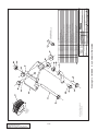
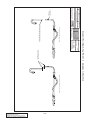
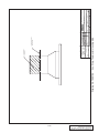
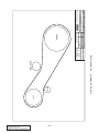
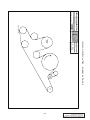
1
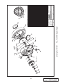
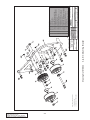
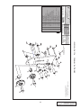
Owner’s Installation Guide for the
Paxton Automotive
Novi 1000 Supercharger
WITH PAXTON HEADERS
for the
2000/2001Plymouth Prowler
Paxton Automotive . 1300 Beacon Place . Oxnard CA 93033
(805 604-1336 . FAX (805) 604-1337
DP/N: 4809629 - V2.0
10/22/02
FOREWORD
Proper installation of this supercharger kit requires general automotive mechanic knowledge and experience. Please browse
through each step of this instruction manual prior to beginning
the installation to determine if you should refer the job to a professional installer/technician. Please call Paxton Automotive for
installers in your area.
© 2003 PAXTON AUTOMOTIVE
All rights recerved. No parts of this publication may be reproduced, transmitted, transcrived, or translated into
another language in any form, by any means without written permission of Paxton Automotive.
P/N: 4809629
©2003 Paxton Automotive
All Rights Reserved, Intl. Copr. Secured
22OCT02 v2.0 PlymProwler(4809629v2.0)
ii
TABLE OF CONTENTS
FOREWORD . . . . . . . . . . . . . . . . . . . . . . . . . . . . . . . . . . . . . . . . . . . . . . . . . . . . . . . . . . . . . . . . .ii
TABLE OF CONTENTS . . . . . . . . . . . . . . . . . . . . . . . . . . . . . . . . . . . . . . . . . . . . . . . . . . . . . . . .iii
IMPORTANT NOTES . . . . . . . . . . . . . . . . . . . . . . . . . . . . . . . . . . . . . . . . . . . . . . . . . . . . . . . . . .iv
1.1 PROWLER HEADER INSTALLATION INSTRUCTIONS
1-1
2.1 DISASSEMBLY
2-1
3.1 NOVI 1000
3-1
4.1 INSTALLING OIL FEED FITTINGS
4-1
5.1 THE POWER STEERING SYSTEMMODIFICATION
5-1
6.1 MODIFY AND RELOCATE THE ALTERNATOR/ INSTALL BELT TENSIONERS
6-1
7.1 INSTALL THE MOUNTING BRACKET ASSEMBLY AND SUPERCHARGER
7-1
8.1 FAN MODIFICATION
8-1
9.1 FUEL LINE MODIFICATION
9-1
10.1 INSTALLING THE BOOST GAUGE (APPENDIX 1018105)
10-1
11.1. FUEL SYSTEM MODIFICATION
11-1
12.1 INSTALLING THE AIR INTAKE ASSEMBLY (APPENDIX 1016043)
12-1
13-1 FINAL CHECK-OUT PROCEDURES
13-1
APPENDICES . . . . . . . . . . . . . . . . . . . . . . . . . . . . . . . . . . . . . . . . . . . . . . . . . . . . . . . . . . . . . . .A-1
Drawing No. 1201711 Kit, Parts List 1997-2000 Prowler . . . . . . . . . . . . . . . . . . . . . . . . .A-2
Drawing No. 1011811
Asy, Novi 1000 Supercharger . . . . . . . . . . . . . . . . . . . . . . . . . . . .A-3
Drawing No. 1016034 Asy, S/C Mounting Bracket . . . . . . . . . . . . . . . . . . . . . . . . . . . . . .A-4
Drawing No. 1016032 Asy, A/C Tensioner . . . . . . . . . . . . . . . . . . . . . . . . . . . . . . . . . . . .A-5
Drawing No. 1016033 Asy, Tensioner Drive Belt . . . . . . . . . . . . . . . . . . . . . . . . . . . . . . .A-6
Drawing No. 1016043 Asy, Air Intake . . . . . . . . . . . . . . . . . . . . . . . . . . . . . . . . . . . . . . .A-7
Drawing No. 1016046 Asy, Power Steering Relocation . . . . . . . . . . . . . . . . . . . . . . . . . . .A-8
Drawing No. 1016049 Asy, Air Discharge . . . . . . . . . . . . . . . . . . . . . . . . . . . . . . . . . . . .A-9
Drawing No. 1016055 Asy, Radiator Tube Modification . . . . . . . . . . . . . . . . . . . . . . . . .A-10
Drawing No. 1019347 Asy, Oil Supply . . . . . . . . . . . . . . . . . . . . . . . . . . . . . . . . . . . . . .A-11
Drawing No. 1019346 Asy, Oil Return . . . . . . . . . . . . . . . . . . . . . . . . . . . . . . . . . . . . . .A-12
Drawing No. 1015513 Asy, Compressor Bypass . . . . . . . . . . . . . . . . . . . . . . . . . . . . . . .A-13
Drawing No. 1016069 Asy, Alternator Relocation . . . . . . . . . . . . . . . . . . . . . . . . . . . . . .A-14
Drawing No. 7000180 Diag, Power Steering Line Mod . . . . . . . . . . . . . . . . . . . . . . . . . .A-15
Drawing No. 1017717 Asy, Fuel Control . . . . . . . . . . . . . . . . . . . . . . . . . . . . . . . . . . . . .A-16
Drawing No. 1018105 Asy, Gauge Mounting . . . . . . . . . . . . . . . . . . . . . . . . . . . . . . . . . .A-17
Drawing No. 7000100 Asy, Diag, Power Steering Line Mod . . . . . . . . . . . . . . . . . . . . . .A-18
Drawing No. 7000105 Asy, Diag, Thermostat Housing Mod . . . . . . . . . . . . . . . . . . . . . .A-19
Drawing No. 7000110 Asy, Belt Routing . . . . . . . . . . . . . . . . . . . . . . . . . . . . . . . . . . . . .A-20
Drawing No. 7000110 Diag, Wiring Fuel Controller . . . . . . . . . . . . . . . . . . . . . . . . . . . .A-21
Drawing No. 7000145 Diag, Relay Witing . . . . . . . . . . . . . . . . . . . . . . . . . . . . . . . . . . . .A-22
iii
P/N: 4809629
©2003 Paxton Automotive
All Rights Reserved, Intl. Copr. Secured
22OCT02 v2.0 PlymProwler(4809629v2.0)
2000-2001 Plymouth Prowler
IMPORTANT NOTES
Congratulations! You have purchased the finest street supercharger available for the 2000-2001 Plymouth
Prowler. The centerpiece of this kit is the High Efficiency Paxton NOVI 1000 Supercharger, a mechanically driven centrifugal blower.
This kit comes with all of the parts you will need to install the supercharger. This instruction manual has
been grouped in order of sequence, with photographs and drawings to illustrate the text. This will allow
you quick part identification and orientation.
The installation will require metric and SAE wrenches and sockets, Phillips and standard head screwdrivers, pliers, wire cutters and a wire crimping tool, a selection of pails or buckets for the collection and
storage of motor fluids, an air impact gun (and air compressor), and a 3/8” NPT tap.
We suggest that you obtain a Prowler shop manual and become familiar with the details of your car’s system. Manuals may be obtained from your local Plymouth dealer, or you can order one from Helm
Publications at (800) 782-4356. If your vehicle is not within the normal operating parameters, we do not
recommend the use of a supercharger.
For best results, we suggest that you read this entire manual before beginning. Be familiar with the process
and identify the areas of the car that you will be working on. The average installation time is 14-16 hours.
Your actual install time will depend on your personal skill level, experience installing superchargers, working conditions, and preparedness for the job at hand. This estimate does not include time for the initial
vehicle inspection, cleaning, fine tuning, or troubleshooting. Once again, before picking up a wrench, read
this entire manual. We are available for technical assistance at (805) 604-1336 between the hours of 7am3PM Monday through Friday PST.
After reading this manual, verify that all major assembly groups are present in the main kit box. You
should have ample space to lay out the components. As you remove a box or bag from the main kit, note
the identification label and compare it with the parts list.
Paxton Automotive makes every effort to insure that all
parts are included in the box, but mistakes do occur. If
you discover that you are missing any part, or
that a part is damaged in transit, please call
Paxton Automotive for service. DO NOT attempt installation
if any part(s) are missing from this kit. Failure to contact
Paxton prior to beginning installation will
result in a charge for any missing parts.
Before starting the installation, we suggest that the engine and engine compartment be clean. You can
clean the engine with a pressure washer, such as those used at self-serve car washes. Use a safe-for-aluminum cleaner/degreaser, and cover the distributor with a plastic bag to prevent water from entering.
P/N: 4809629
©2003 Paxton Automotive
All Rights Reserved, Intl. Copr. Secured
22OCT02 v2.0 PlymProwler(4809629v2.0)
iv
You are undoubtedly eager to get started with your project, but take a little more time to insure that your
safety is not in jeopardy. A moment’s lack of attention can result in an accident, as can failure to observe
some simple safety precautions. The possibility of an accident always exists, and the following points
should not be considered a comprehensive list of all of the dangers. They are only intended to make you
aware of the risks and to encourage you to take a safety conscious approach to all of the work that you will
be doing on your vehicle.
•
Never rely solely on a jack when working under a vehicle. Always
use an approved set of jackstands to support the vehicle and place
them under the recommended lift points.
•
When jacking a vehicle, make sure it is on a level surface, preferably concrete or asphalt. The transmission should be in “PARK”
or “FIRST”, the parking brake engaged and the wheels blocked.
•
Never start the car without first verifying that the transmission is in
neutral and the parking brake is set.
•
Never remove the radiator cap while the engine is hot.
•
Always wear eye protection when using power tools such as drills,
saws, grinders, etc., or when working under a vehicle.
•
Never smoke, use an open flame, or have spark-producing items
around gasoline or flammable solvents. Always have a fire extinguisher rated for chemical and electrical fires handy when working
on motor vehicles.
•
Run engines only in well ventilated areas. Carbon monoxide, gasoline, and solvent vapors are colorless and sometimes odorless.
These can asphyxiate or explode without warning.
•
Always disconnect at least the negative (-) or ground terminal of the
battery when doing any electrical, fuel system, or underdash work.
We look forward to hearing from you, particularly if you have any comments or suggestions
regarding this manual.
v
P/N: 4809629
©2003 Paxton Automotive
All Rights Reserved, Intl. Copr. Secured
22OCT02 v2.0 PlymProwler(4809629v2.0)
This Page Left Intentionally Blank.
P/N: 4809629
©2003 Paxton Automotive
All Rights Reserved, Intl. Copr. Secured
22OCT02 v2.0 PlymProwler(4809629v2.0)
vi
Section 1
HEADER INSTALLATION
1.1
PROWLER HEADER INSTALLATION
INSTRUCTIONS
*****IMPORTANT*****
Once the headers and cats are finish welded and
installed, pay close attention to any hoses, wires
etc., that may be touching the headers. Move
any of these objects out of the way. If you wish
to use any conforming heat shields, wrap the
part but NOT THE HEADERS. The headers need
to "breathe". Wrapping it with a shield will damage it in time.
A. Raise vehicle approximately 2 feet off the
ground, preferably using a lift. The only way
to install the headers is to work from the
bottom, so use either ramps or heavy-duty
jack stands to get the vehicle to a workable
height. You will need basic metric and
American tools for disassembly.
B. Remove the stock manifolds and catalytic
converters. Clean out any carbon buildup
from the heads. Install the studs provided in
the kit using a torx socket to tighten. After
the studs are tightened, place the gaskets
over the studs and install the headers.
D. When everything is done and inspected start
the vehicle and check for leaks. If everything looks good, let it idle for appoximately
15 minutes. Shut it off and re-tighten the
header bolts. New bolts and or studs will
stretch once when hot. You will notice a normal rate of approximately 1/2 turn to tighten. Once this is completed you are ready to
go.
*****NOTE*****
You may need to enlarge the holes in the headers with a file to ease assembly. Use the lock
washers provided in the kit and tighten equally.
After the headers are tightened, refer to
attached diagram to see where to cut the
stock head pipe away from the cats. Once
the stock head pipes are removed, insert the
cats back into the factory slip fits.
C. Fasten the 3-bolt flanges and gaskets finger
tight to the headers. Position the cats to
index into the blank flanges bolted to the
new headers.
*****Note*****
The tube size on the stock cat is 2-1⁄4" and the
header collector is 2-1/2" We recommend taking
the cats to a muffler shop and having them
expanded to better fit the flange. Once this is
done, position both cats in their factory slip fits
and index into the new headers. Using a mig
welder tack the cat to the flanges in at least
three places. Remove the cats and finish weld.
Re-install the cats using the lock washers
included in the kit. Tighten the 3 bolt flange
joints first then the factory slip fits last.
1-1
P/N: 4809629
©2003 Paxton Automotive
All Rights Reserved, Intl. Copr. Secured
22OCT02 v2.0 PlymProwler(4809629v2.0)
*****NOTE*****:
You may notice a “burning rubber” smell when
the vehicle is first fired up and immediately after
the first long hard full throttle pulls you do. This
is caused by the special composition header
gaskets “burning in” and takiing a set. However,
please feel free to check and double-check that
no hoses or rubber components are beinng
incinerated.
PROWLER DIAGRAM
For removing stock head pipe for header installation
STOCK HEAD PIPE 2-1/4”
MEASURE 1/4” ABOVE WELD, CUT AND REMOVE USING A BASIC MUFFLER
SHOP EXPANDER OR HAND HELD. EXPAND THIS UP TO 2-1/2” O.D.
2-1/2” 3-BOLT FLANGE
BOLT FLANGE TO COLLECTOR INDEX
CAT INTO FLANGE TACK WELD OUTSIDE
REMOVE AND FINISH WELD INSIDE
P/N: 4809629
©2003 Paxton Automotive
All Rights Reserved, Intl. Copr. Secured
22OCT02 v2.0 PlymProwler(4809629v2.0)
1-2
Section 2
SUPERCHARGER INSTALLATION
2.1
DISASSEMBLY
A. Disconnect the battery
B. Using a 10mm socket, remove the 3 bolts
securing the body panel immediately in front
of the driver’s door. Pull it out at the top
then lift up to remove. Disconnect the side
marker light. (See Fig. 2-1.)
C. Using a 13mm socket, disconnect the support rods (that go over the top of the engine)
at the rear of the engine compartment.
Leave them connected to the radiator support plate. (See Fig. 2-2.)
REMOVE
DISCONNECT
SUPPORT RODS
Fig. 2-1
E.
REMOVE
Fig. 2-2
D. Using a 13mm and a 10mm socket, disconnect the upper radiator support and remove
the upper radiator support and the support
rods covering the engine. If your car has the
hood support as part of this assembly, you
will need a prop rod to support the hood
during the rest of the installation. (See
Fig. 2-2.) Place the front end of the car on
jackstands as near to the engine supports as
possible. (See Fig. 2-3.)
Disconnect the plug at the top of the fan
shroud (see Fig. 2-4). From under the vehicle, loosen the petcock on the passenger side
of the radiator and completely drain the
coolant into a bucket. If coolant is not
reusable, please dispose of it properly.
Disconnect both upper and lower and radiator hoses and remove the lower radiator
hose. Disconnect the wiring harness from
the fan shroud. Using a 10mm socket,
remove the two bolts that secure the radiator
to the A/C condenser, and remove the radiator by lifting it straight up.
WIRING
HARNESS
Fig. 2-4
Fig. 2-3
2-1
P/N: 4809629
©2003 Paxton Automotive
All Rights Reserved, Intl. Copr. Secured
22OCT02 v2.0 PlymProwler(4809629v2.0)
Using masking tape, mark the edges of the
support brace that the body side panel was
bolted to. This will help you in the reassembly. (See Fig. 2-5.)
G. Disconnect the plug to the hood switch, and,
if needed, disconnect the driver’s side hood
piston. Unbolt the power steering reservoir
bracket. Remove the six 13mm head bolts
securing the support brace (that was marked
in step 6). Use a 60º offset wrench to
remove the two bolts closest to the driver’s
side headlight. Disconnect the wiring harness from the support brace and remove the
brace.
F.
Fig. 2-6
M. If required, remove the belt guard near the
A/C compressor using a 13mm socket.
N. Remove the passenger side body side panel
as you did the driver’s side panel in step 2 to
gain access to the air filter box, and remove
the box assembly from the vehicle.
Disconnect and remove the plastic pipe
going into the throttle body. You will have to
loosen the coolant overflow bottle from the
frame in order to create enough space to
remove the air box. Disassembling the air
box and removing the filter and box in
pieces simplifies the removal.
O. Disconnect the heater hose from the thermostat. (Make sure that you have a drain pan
directly underneath it.) Remove the thermostat housing using a 10mm socket. Modify
the thermostat housing, as shown in
Appendix 7000105. Pry the heater pipe
slightly away from the neck so that the radiator hose will slide back on. (See Fig. 2-7.)
Be careful not to cave in the neck.
Reconnect the heater hose and reinstall the
thermostat housing using the original gasket
Fig. 2-5
H. Ease the tension on the 6 rib belt by loosening the 15mm nut on the tensioner pulley,
then loosen the 13mm head lead screw.
Remove the belt.
I. Drain the power steering fluid by disconnecting the large hose at the pump and the
smaller hose near the steering rack. Remove
the reservoir, hood switch assembly, and
lines. Remove the two plastic clips that
secure the metal lines from the rack and pinion. Disconnect the metal line that runs from
the pump to the rack and pinion and remove.
J. Disconnect the electrical connections to the
alternator and use a 15mm socket to remove
the alternator, alternator bracket, and brace.
(See Fig. 2-6.)
K. Remove the three 13mm head bolts securing
the Drive Belt tensioner to the front of the
engine. Remove the tensioner.
L. From underneath the vehicle, remove the
A/C belt using the same procedure as in step
8. Remove the two 15mm bolts that secure
the tensioner assembly and remove the
assembly.
Fig. 2-7
P/N: 4809629
©2003 Paxton Automotive
All Rights Reserved, Intl. Copr. Secured
22OCT02 v2.0 PlymProwler(4809629v2.0)
2-2
Section 3
INSTALLING SUPERCHARGER DRAINBACK
***NOTE:***
For this step you will need a drill motor, 3/16”
and 37/64 drill bits, 3/8 x 16 NPT tap, anti-seize
lubricant and heavy grease.
3.1
NOVI 1000
A. The Paxton Automotive Novi 1000 supercharger relies on pressurized engine oil for
its lubrication. The oil must then be returned
to the oil pan, via a drain back fitting that
must be installed into the pan. This involves
making a hole in the driver’s side of the oil
pan. To do this, first drain 1 quart of oil
from the pan, then scribe an X into the oil
pan 1-1/2” forward of the rib and 3/4-inch
below the pan rail. After the X is scribed,
drill a 3/16-inch pilot hole into the center of
the X. See Fig 8 for the general placement
of the Oil Drain fitting.
B. Enlarge the pilot hole with the 37/64-inch
drill.
C. Apply a liberal amount of grease to the
threads of a 3/8-inch X16 NPT tap, and
slowly insert into the hole. The grease will
make tapping the hole easier, and will also
keep metal chips from falling into the pan.
Tap the hole until the fitting tightens 3/4 of
the way into the hole.
Fig. 3-1
E.
Drain the rest of the oil and fill with
factory recommended oil.
*****NOTE*****:
This fitting has tapered threads and is intended
not to seal flush against the drain pan.
D. Clean the finished threads with a clean rag.
Apply a sparing amount of sealer such as
silicon RTV to the threads of the supplied
drain back fitting, and install.
*****NOTE*****:
Do not over-tighten.The finished Oil Drain is in
Fig. 3-1. Please note that the hose is shown in
this picture, but it is not to be connected at this
time.
3-1
P/N: 4809629
©2003 Paxton Automotive
All Rights Reserved, Intl. Copr. Secured
22OCT02 v2.0 PlymProwler(4809629v2.0)
This Page Left Intentionally Blank.
P/N: 4809629
©2003 Paxton Automotive
All Rights Reserved, Intl. Copr. Secured
22OCT02 v2.0 PlymProwler(4809629v2.0)
3-2
Section 4
INSTALLING THE OIL FEED FITTINGS
4.1
INSTALLING OIL FEED FITTINGS
A. Using a 13mm socket, remove the three
mounting bolts that secure the power steering pump. (You can get to the bolts through
the openings in the pulley.) Let the pump
hang by the lines. Remove the oil pressure
sender using a special 1-1/16” oil pressure
sender socket. This can be found at most
auto parts stores. Install the supplied large
hex fitting using either liquid teflon or RTV
sealant. Tighten the fitting using 1-1/8”
socket or wrench. It is correctly positioned
when the large tapped hole points straight
down. Install the factory oil pressure sender
into the hex fitting using sealant. Now,
install the supplied 90º fitting into the
remaining hole. It should aim up and back,
over the oil filter. Reattach the power steering pump and attach the electrical plug to
the sender. (To get more slack in the sender
wire, carefully remove the tape securing it
near the intake manifold. This will free up
the two or three inches bundled up inside).
Attach one end of the oil feed line to the 90º
fitting and tighten. See Appendix Number
1016059.
4-1
P/N: 4809629
©2003 Paxton Automotive
All Rights Reserved, Intl. Copr. Secured
22OCT02 v2.0 PlymProwler(4809629v2.0)
This Page Left Intentionally Blank.
P/N: 4809629
©2003 Paxton Automotive
All Rights Reserved, Intl. Copr. Secured
22OCT02 v2.0 PlymProwler(4809629v2.0)
4-2
Section 5
MODIFICATION OF THE POWER STEERING SYSTEM
5.1
THE POWER STEERING SYSTEMMODIFICATION
A. Mount the supplied power steering
reservoir to the frame rail in front of
the hood release and next to the driver’s
side headlight. Drill two 11/64” holes
and secure the reservoir using the supplied hardware. (See Fig. 5-1.)
Fig. 5-2
New power steering reservoir, mounted on
frame rail. Showing hoses going through the frame.
C. Cut the existing metal tube and flare
the ends with a pair of pliers.
(See Fig. 5-3.)
Fig. 5-1
B.
Route the 5/8”power steering hose to
the new reservoir through the same
notch as the battery cables go through.
It may be helpful to flatten a section of
the fins on the bottom of the A/C condenser to ease the routing. Route the
3/8” hose around the end of the A/C
condenser on the driver’s side.
The line from the Power Steering Pump
to the Rack and Pinion is modified, per
7000100. Reinstall the line and check
for the correct orientation. If it is not
correct, loosen the fitting and rotate.
Reinstall the plastic clip to hold the line
in place, as shown in Fig 5-2.
Fig. 5-3
Install the existing rubber hose and
hose clamps. The metal line is reversed,
so that the same end remains attached
to the curved rubber tube. Attach the
metal line to the new reservoir with the
provided 5/8” rubber hose.
5-1
P/N: 4809629
©2003 Paxton Automotive
All Rights Reserved, Intl. Copr. Secured
22OCT02 v2.0 PlymProwler(4809629v2.0)
D. The line from the Rack and Pinion to
the reservoir is left the same, except for
the new rubber line from the reservoir.
Secure the Power Steering hoses and
trim as needed for best fit. Shown are
the various parts of the system.
A
C
B
Fig. 11
Shows both the new reservoir-pump line (A), the
rack-and-pinion pump line (B) and the clip (C).
The rack-reservoir line (A) remains the same.
Fig. 12
The new 3/8” line from the reservoir.
***NOTE:***
Refill with factory recommended power steering
fluid only.
P/N: 4809629
©2003 Paxton Automotive
All Rights Reserved, Intl. Copr. Secured
22OCT02 v2.0 PlymProwler(4809629v2.0)
5-2
Section 6
MODIFY AND RELOCATE THE ALTERNATOR
AND INSTALL THE BELT TENSIONER
6.1
MODIFY AND RELOCATE THE
ALTERNATOR/ INSTALL BELT TENSIONERS
C. LOOSELY bolt the alternator mounting
bracket to the engine block where the A/C
tensioner was bolted (see Fig. 6-2).
A. Extend the alternator wiring harness using
the supplied wires. Cut the eyelet off of the
large power wire (this may be either red or
black) and connect to the supplied large red
wire.
*****NOTE:*****
The butt connectors supplied in the kit are the
heat-shrink type. After crimping, use a heat gun
or lighter to shrink the ends for a water tight fit.
The connector is water tight when glue bubbles
out of the ends.
B.
Next, cut the wires leading to the two wire
plug about 6 inches from the plug and attach
the supplied extension wires. Cover the
wires with the supplied split loom and route
along the bottom of the radiator, and the
lower frame rail on the passenger side to the
alternator. DO NOT attach the plug yet. You
will first mount the alternator then cut the
wires to length.
Remove the factory alternator pulley cap
and using an impact gun with a 17mm allen
head socket remove the stock pulley. (See
Fig. 6-1.) Install the supplied pulley in its
place securing with supplied 17mm nut.
Heating the pulley will make the installation
easier.
Fig. 6-2
Install the supplied drive belt tensioner plate
with the spacer (see Fig. 6-3). Align the
crank and drive belt pulleys, and tighten the
bolts on the drive belt tensioner plate and
the alternator mounting plate using a 17mm
socket
*****NOTE:*****
Do not use the washer supplied with the alternator pulley nut.
Fig. 6-3
Fig. 6-1
6-1
P/N: 4809629
©2003 Paxton Automotive
All Rights Reserved, Intl. Copr. Secured
22OCT02 v2.0 PlymProwler(4809629v2.0)
D. Bolt the alternator support arm to the ear on
the alternator. Leave it slightly loose so it
can be adjusted. Next, mount the alternator
to the bracket. You will have to bend the Oil
Dipstick tube up and away from the bracket
to make room for the alternator.
(See Fig. 6-4.)
Fig. 6-5 /
Complete installed Drive Belt Tensioner.
I.
Refer to Fig. 6-6. Replace the factory bolts
with two 6mm Buttonhead screws from the
A/C Tensioner Assembly (p/n 1016032).
Fig. 6-4
Loop the supplied V-belt around the crank
pulley, then around the A/C compressor.
F. Remove the two 10mm head nut and bracket, the 15mm head bolt/stud and the 15mm
head bolt.
G. To install the A/C tensioner, place the belt
over the lower pulley, then under the top
adjuster pulley.
E.
*****NOTE:*****
The tensioner pulley will push down on the belt,
so make sure the pulley is at the uppermost
position. Now bolt the bracket to the engine.
Tighten the bolt by turning the screw counter-clockwise. When the bolt is sufficiently
tight, tighten the lock nut on the front of the
A/C tensioner assembly.
H. Complete the alternator wiring. Install the
drive belt tensioner. (See Fig. 6-5.)
P/N: 4809629
©2003 Paxton Automotive
All Rights Reserved, Intl. Copr. Secured
22OCT02 v2.0 PlymProwler(4809629v2.0)
Fig. 6-6
6-2
Section 7
INSTALL THE MOUNTING BRACKET ASSEMBLY
AND SUPERCHARGER
7.1
INSTALL THE MOUNTING BRACKET
ASSEMBLY AND SUPERCHARGER
A. Remove the two 10mm Head Bolts and
replace them with the Buttonhead allen bolts
supplied with the mounting bracket assembly (P/N: 1016034). (See Fig. 7-1.)
PUT THESE
BOLTS IN
FIRST
10mm HEAD BOLTS
Fig. 7-3
S/C Mounting bracket from rear of engine
Fig. 7-1
B.
C. Test fit the supercharger by laying it into the
mounting bracket. You will need to trim the
body panel for clearance. Do not permanently attach the supercharger yet.
(See Fig. 7-4.)
Bolt the supercharger mounting bracket to
the front of the engine using the four 8mm
bolts and one 10mm bolt (See Appendix
1016034 for the proper bolt placement.) The
bracket fits behind the power steering pulley. You must put the 3/8-16 x 3-1/4” long
bolts (item #8) in the lowermost outer holes
in the bracket before installation. (See Figs.
7-2, 7-3.) shows the installed Mounting
Bracket.
POWER STEERING
PULLEY
Fig. 7-4
Fig. 7-2
S/C mounting bracket from front of engine (pulleys attached).
7-1
P/N: 4809629
©2003 Paxton Automotive
All Rights Reserved, Intl. Copr. Secured
22OCT02 v2.0 PlymProwler(4809629v2.0)
D. Install the oil drain fitting on the supercharger. Install a 2” long turbo hose (from the discharge tube assembly p/n 1016049) onto the
discharge of the supercharger using a #48
hose clamp (place the screw of the clamp in
towards the supercharger). (See Fig. 6-4.)
*****NOTE*****
The discharge tube points straight down. Start
the three countersink allen bolts and tighten
using a 7/32 allen wrench. Go back and tighten
the 3/8” bolts, using a 9/16 socket.
Attach the oil feed and oil drain hoses to the
supercharger, making sure they won’t come
in contact with the exhaust manifold, hot
engine surfaces, or hit anything when the
engine rocks. The oil drain fitting can be
turned to make adjustments in the line placement.
H. Affix the remaining smooth idler pulley to
the last open hole in the mounting bracket.
Install the accessory/supercharger drive belt.
(See diagram 7000110.)
TURBO SLEEVE
OIL DRAIN
Fig. 6-4
E.
F.
Install the supplied Lower Radiator hose
(P/N: 1016055) to the engine.
Relocate the wiring harness that runs underneath the supercharger by drilling a new
hole and attaching the harness with a ZipTie.
(See Fig. 6-5.)
NEW HOLE
DRILLED
Fig. 6-5
G. Mount the supercharger to the bracket, but
leave the four 3/8” bolts slightly loose.
P/N: 4809629
©2003 Paxton Automotive
All Rights Reserved, Intl. Copr. Secured
22OCT02 v2.0 PlymProwler(4809629v2.0)
7-2
Section 8
FAN MODIFICATION
8.1
FAN MODIFICATION
A. Install spacers between the fan and the
shroud. Detach the fan from the support
brace by removing the two mounting screws
and popping the spring clips (see Fig 8-1).
Place the three spacers between the motor
and the fan shroud (see Fig. 8-3). This will
space the back of the fan motor away from
the engine slightly. Reassemble the fan.
3 SPACERS
REMOVE SPRING CLIPS
Fig. 8-3
Fig. 8-1
Remove the spring clip that retains the fan
(see Fig. 8-2) and remove the three screws
using an internal Y-27 torx socket (This is a
hard to find size. If you do not have one, a
pair of pliers will do the job.)
Fig. 8-2
8-1
P/N: 4809629
©2003 Paxton Automotive
All Rights Reserved, Intl. Copr. Secured
22OCT02 v2.0 PlymProwler(4809629v2.0)
This Page Left Intentionally Blank.
P/N: 4809629
©2003 Paxton Automotive
All Rights Reserved, Intl. Copr. Secured
22OCT02 v2.0 PlymProwler(4809629v2.0)
8-2
Section 9
FUEL LINE MODIFICATION
9.1
FUEL LINE MODIFICATION
A. Please refer to Appendix 1016049 for the
attachment of the S/C discharge tube. It will
travel from the supercharger, underneath the
car, up between the engine and the firewall,
and connects to the throttle body. Begin by
attaching item number 4 to the throttle body
at the rear of the engine and tighten both
clamps on the factory elbow. Install the
mounting hardware from the stock plastic
part that is attached to the throttle body (see
Fig. 9-1)
STOCK HARDWARE
Fig. 9-2
You will have to remove a plastic cover and
the Schraeder Valve to make the connection.
At this time, it is also recommended that the
spark plugs be changed to AUTOLITE
5224, or equivalent, gapped to .035. Do not
use Platinum Spark Plugs with the supercharger.
C. Attach the Compressor Bypass Assembly to
the discharge tube. (See Appendix 1016066).
Notice that the “T” fitting (item 5) goes
between the Vacuum Reservoir and the
Vacuum Branch next to the Brake Booster.
Connect the vacuum line going to the Boost
Gauge to the other “T’ fitting. The Boost
Gauge Vacuum line goes through the body
panel through the grommet and comes out
under the steering column. (See Fig. 9-3.)
Fig. 9-1
B.
Then, from underneath the vehicle, attach
item 1, the cast discharge tube, to the turbo
hose that you previously attached to the
supercharger. Attach item 6 to the throttle
body side, and finally attach item 5 to connect both ends. Make sure all of the clamps
are tightened properly. Make sure that the
Discharge Tube is level as it passes under the
vehicle, and that it will clear the ground.
Adjustments can be made at either end at the
Turbo Sleeve connectors.
The fuel line from the discharge tube assembly will need to be routed at this point. The
fuel line needs to be routed along the firewall (being careful to avoid any exhaust or
potentially hot surfaces), under the back of
the manifold, and to connect with the fitting
on the side of the fuel rail (see Fig. 9-2).
Fig. 9-3
9-1
P/N: 4809629
©2003 Paxton Automotive
All Rights Reserved, Intl. Copr. Secured
22OCT02 v2.0 PlymProwler(4809629v2.0)
D. Modify upper radiator support as shown (see
Fig. 9-4).
Fig. 9-4
E.
Reinstall the radiator into the vehicle. Plug
in the fan harness. Connect the upper and
lower radiator hoses. Reattach the condensor
to the radiator with the two 6mm factory
bolts.
P/N: 4809629
©2003 Paxton Automotive
All Rights Reserved, Intl. Copr. Secured
22OCT02 v2.0 PlymProwler(4809629v2.0)
9-2
Section 10
INSTALLING THE BOOST GAUGE
10.1 INSTALLING THE BOOST GAUGE
(APPENDIX 1018105)
A. The studs on the back of the Boost Gauge
will have to be cut off to make it fit into the
mounting cup.
B. Splice the wires that are supplied in the
assembly to the Boost Gauge. Disconnect
the socket and bulb from the gauge to ease
the wiring.
C. Remove the panel from under the steering
column (two bolts, see Fig. 10-1).
Fig. 10-2
Take the Vacuum Line (from step 38) and
feed it up the steering column and the Boost
Gauge Sheath. Attach the vacuum line to the
Boost Gauge using the supplied fitting, per
the installation instruction that are provided
with the gauge. Route the wiring harness
back to the top of the steering column.
Check the placement of the line, to make
sure that it will not kink when the steering
column is tilted.
G. Reinstall the socket and bulb into the Boost
Gauge.
H. Reinstall the steering column panel, once
again watching for kinks in the vacuum line.
I. Attach the RPM and Boost gauges to the
mounting brackets and the steering column
as shown in Appendix 1018105.
F.
Fig. 10-1
D. Disconnect the wiring harness to the RPM
Gauge and route to the bottom of the steering column.
E. Trim the sleeving on the wiring harness to
access the wires to the RPM Gauge.
Connect the Boost Gauge wires to the RPM
Gauge wires (Black to Black and White to
Orange). (See Fig. 10-2.)
10-1
P/N: 4809629
©2003 Paxton Automotive
All Rights Reserved, Intl. Copr. Secured
22OCT02 v2.0 PlymProwler(4809629v2.0)
This Page Left Intentionally Blank.
P/N: 4809629
©2003 Paxton Automotive
All Rights Reserved, Intl. Copr. Secured
22OCT02 v2.0 PlymProwler(4809629v2.0)
10-2
RED WIRE, FROM RELAY TO
Section 11
FUEL SYSTEM MODIFICATIONS
11.1. FUEL SYSTEM MODIFICATION
Yellow. Cut the wire in the same area, and
connect the ECU side to the Tan and Yellow
wire in the controller, and the other side to
the Tan wire.
F. Next locate the Gray and black connector on
the ECU harness find the Yellow/Black wire
this should be Pin #73 in this connector.
G. The Paxton fueler and Ignition box needs an
RPM signal to operate you just have to TEE
into this wire for the correct signal.
H. Close the ECU harness. Make sure that your
Butt Connectors have a good seal, and place
them into the wiring harness.
I. Connect the Vacuum Tube from the controller to the Intake Manifold Vacuum. This
is done with the included adapter and line.
You will have to remove a factory cap on
the manifold to make the connection. (See
Fig. 11-2.)
*****NOTE:*****
Refer to Appendices 1017717 (Asy, Fuel
Control), 7000125 and 7000145 (Wiring
Diagrams) and the photo (next page) for this
section. The Controller (4PCA016-011) will connect to the Factory Stock ECU, the Fuel
Injectors, and the Boost Retardant Device. All
will be accessed from the passenger side, where
the side body panel was removed.
(See Fig. 11-1.)
ECU AND HARNESS
Fig. 11-1
A. Before working on the vehicle’s electrical
system, make sure that the battery has been
disconnected.
B. Disconnect the plugs from the ECU and
remove the ECU using a 7mm socket on the
3 mounting bolts and then open up the wire
harness (split loom) that leads out of the
ECU unit. (Refer to the wiring diagram in
the Appendix page A-23 for wire color and
pin location.)
C. Open up the ECU harness on the Prowler.
Locate the wire connected to the Crank
Sensor (it will be connected to the #32 lead,
and should be Gray and Black).
D. Cut the wire. It should be cut in the area of
the wiring harness. The end that comes from
the ECU will be connected to the
Gray/Black wire on the Controller. The
other end will be connected to the Gray
wire. Use the heat shrink Butt Connectors to
insure a water tight seal.
E. The CAM sensor wires will be connected to
the #33 connection, and will be Tan and
Fig. 11-2
The controller is now ready to be connected
to a power source. The RED (Power) wire is
connected to terminal 87 on the relay with a
female disconnect (crimp and shrink type.
The Relay will be installed on the upper
mounting bolt behind the controller.
K. The black (ground) wire from the controller
will be connected to the ground on the side
of the ECU with a crimp type of ring terminal.
J.
11-1
P/N: 4809629
©2003 Paxton Automotive
All Rights Reserved, Intl. Copr. Secured
22OCT02 v2.0 PlymProwler(4809629v2.0)
TO MANIFOLD VACUUM/BOOST
TO INJECTORS
RED WIRE, FROM RELAY TO
FUSE BOX (POWER)
TO CAM, CRANK AND
RPM SENSORS
BLACK WIRE, FROM RELAY
TO FUSE BOX (POWER)
BLACK WIRE, FROM RELAY
TO FUSE BOX (GROUND)
RED WIRE, FROM
CONTROLLER TO RELAY
GRAY WIRE, FROM THE RELAY
TO THE FUSE BOX (TRIGGER)
RELAY PLUG, TO BE MOUNTED ON THE
FRAME BEHIND THE CONTROLLER
Fig. 11-3
P/N: 4809629
©2003 Paxton Automotive
All Rights Reserved, Intl. Copr. Secured
22OCT02 v2.0 PlymProwler(4809629v2.0)
11-2
SPLIT LOOM, FOR THE
RED, GRAY AND BLACK
WIRES FROM TE RELAY TO
THE FUSE BOX
L.
Power to the relay is supplied by a red wire,
running from the positive (red) terminal on the
fuse box. (See Fig. 11-4.) This wire is attached
to the fuse box with the 3/8” ring connector
and to the relay with a female disconnect on
the 30 terminal relay.
RELAY POWER
Fig. 11-6
O. Remove the plugs, and remove the red plastic relay port by pressing on the tabs in the
corners. (See Fig. 11-7.)
Fig. 11-4
M. Ground to the relay is supplied by the black
wire running from a screw in the frame rail
under the fuse box on the driver’s side. (See
Fig. 11-5.) This wire is attached to the screw
on the frame rail with a ring connector and
to the relay with a female disconnect on the
85 terminal (relay).
Fig. 11-7
P.
Detach the wire to the connector by pressing
on it from the top side with a small screwdriver. (See Fig. 11-8.)
Fig. 11-5
N. Open the Fuse box and find connection #16.
Take the time to number the other connectors for identification to help in the reassembly. (See Fig. 11-6.)
Fig. 11-8
11-3
P/N: 4809629
©2003 Paxton Automotive
All Rights Reserved, Intl. Copr. Secured
22OCT02 v2.0 PlymProwler(4809629v2.0)
Q. Here is the trigger wire for the controller.
(See Fig. 11-9.) Use a provided Quick
Connector to attach the gray wire. The other
end of the trigger wire is connected to the
relay with a female disconnect on the 86 terminal (relay). Reassemble the fuse box.
Fig. 11-11
Next reinstall the ECU. Being sure that the
bolt head is not contacting the ECU. You
may have to space the ECU out using washers. (See Fig. 11-12.)
Fig. 11-9
R. The red, black, and gray wires from the fuse
box are routed along the firewall wiring
loom in the supplied split loom.
S. Before reinstalling the ECU there is an A/C
line that runs close to the header. When you
relocated the Altenator there was a bracket
that you removed from the back of the
Alternator.This will be used to relocate the
A/C line using the supplied hardware. (See
Figs. 11-10, 11-11.)
Fig. 11-12
Fig. 11-10
P/N: 4809629
©2003 Paxton Automotive
All Rights Reserved, Intl. Copr. Secured
22OCT02 v2.0 PlymProwler(4809629v2.0)
11-4
Section 12
INSTALLING THE AIR INTAKE ASSEMBLY
12.1 INSTALLING THE AIR INTAKE
ASSEMBLY (APPENDIX 1016043)
A. Install the supplied 45° fitting and position
to provide the maximum clearance between
the headers and the vent line.
(See Fig. 12-1.)
AIR BOX VENT TUBE
ECU VACUUM
Fig. 12-2
G. Assemble the Air Filter and attach it to the
Air Box. Thread the steel rod (item #11)
through the box, and thread a nut and washer on the end. Place the restrictor, plate, filter element, tube, and plate onto the rod.
Finally, secure the assembly with the knob.
(See Fig. 12-3.)
Fig. 12-1
Attach the adapter hose (item #7) to the
supercharger, using the #48 hose clamp.
Leave clamp loose at this point.
C. Attach the Nipple Fitting (item #12) to the
Compressor Bypass, and then to the Air Box
(item #1). Attach the box to the supercharger.
D. Secure the box to the engine using the
bracket (item #13). You may have to trim
the turbo hose between the supercharger and
air box to clear the headers and fit the
mounting bracket.
E. Tighten all of the clamps at this time.
F. Attach the Vent Tube to the box. The tube is
brought along the firewall splitloom, and
attached to the passenger intake manifold.
(See Fig. 12-2.)
B.
Fig. 12-3
H. Reattach the oxygen sensor to the manifold
and plug back into the electrical connection.
I. Reattach the driver side support rail and the
support rods. Finally, reattach the outer body
panels on the passenger and driver’s side.
12-1
P/N: 4809629
©2003 Paxton Automotive
All Rights Reserved, Intl. Copr. Secured
22OCT02 v2.0 PlymProwler(4809629v2.0)
J.
Reinstall the upper radiator support and support arm assembly using supplied washers
(see Fig. 12-4). While reinstalling, be sure
to push the radiator toward the front of the
vehicle. Refill the radiator with clean
coolant.
Fig. 12-4
Congratulations! Your NOVI 1000 Supercharger is now installed.
Fig. 12-5
P/N: 4809629
©2003 Paxton Automotive
All Rights Reserved, Intl. Copr. Secured
22OCT02 v2.0 PlymProwler(4809629v2.0)
12-2
Section 13
FINAL CHECK
13-1 FINAL CHECK-OUT PROCEDURES
We know that you are anxious to get out and drive your
new vehicle, but please take a little bit more time to
perform these simple check-out steps.
A. Inspect all wiring harnesses and electrical
connections. Make sure that all items are
properly routed, connected and secured.
B. Check all hoses, lines, and fittings for properly secured connections.
C. Make certain all fasteners, brackets, and
clamps are installed and properly tightened.
D. Check serpentine accessory belt and supercharger drive belts for proper tension and
alignment.
E. Cycle ignition key from “off” to the “on”
position.
F. Check the entire fuel system for possible
leaks.
G. Start engine and verify that the oil pressure
is within normal range.
H. Allow the engine to come up to normal
operating temperature.
I. Check the coolant level in the coolant recovery bottle and top off as needed.
J. Check the following:
Fluid Leaks
Fluid Levels
Belt Slippage
Throttle Response
Now that the work is done, it’s time to enjoy. PAXTON
Automotive wants to thank you for choosing our product, and wants to remind you that the performance and
response of your vehicle is now different that what you
are used to. Please drive cautiously until you have
grown accustomed to the feel of your vehicle.
Please see the service manual included in your kit for
information on the service and maintenance of your
PAXTON Supercharger. Belt tightening, troubleshooting, special tuning requirements, and warranty information is also included in the Service Manual.
13-1
P/N: 4809629
©2003 Paxton Automotive
All Rights Reserved, Intl. Copr. Secured
22OCT02 v2.0 PlymProwler(4809629v2.0)
This Page Left Intentionally Blank.
P/N: 4809629
©2003 Paxton Automotive
All Rights Reserved, Intl. Copr. Secured
22OCT02 v2.0 PlymProwler(4809629v2.0)
13-2
Appendices
Thank you for purchasing this Paxton Supercharger. Please understand that because we are constantly improving and upgrading our
product, there may be pictures in this manual showing parts that
appear to be different than the parts in your kit. This may be due to
pictures taken in pre-production, a change in material, or a different model year. Rest assured that the parts will install in the same
fashion, and that you have purchased the most up-to-date kit that
Paxton is selling at this time.
Drawing
Drawing No. 1201711
Drawing No. 1011811
Drawing No. 1016034
Drawing No. 1016032
Drawing No. 1016033
Drawing No. 1016043
Drawing No. 1016046
Drawing No. 1016049
Drawing No. 1016055
Drawing No. 1019347
Drawing No. 1019346
Drawing No. 1015513
Drawing No. 1016069
Drawing No. 7000180
Drawing No. 1017717
Drawing No. 1018105
Drawing No. 7000100
Drawing No. 7000105
Drawing No. 7000110
Drawing No. 7000110
Drawing No. 7000145
Title
Page
Kit, Parts List 1997-2000 Prowler . . . . . . . . . . . . . . . . . . . . . . . . .A-2
Asy, Novi 1000 Supercharger . . . . . . . . . . . . . . . . . . . . . . . . . . . .A-3
Asy, S/C Mounting Bracket . . . . . . . . . . . . . . . . . . . . . . . . . . . . . .A-4
Asy, A/C Tensioner . . . . . . . . . . . . . . . . . . . . . . . . . . . . . . . . . . . .A-5
Asy, Tensioner Drive Belt . . . . . . . . . . . . . . . . . . . . . . . . . . . . . . .A-6
Asy, Air Intake . . . . . . . . . . . . . . . . . . . . . . . . . . . . . . . . . . . . . . .A-7
Asy, Power Steering Relocation . . . . . . . . . . . . . . . . . . . . . . . . . . .A-8
Asy, Air Discharge . . . . . . . . . . . . . . . . . . . . . . . . . . . . . . . . . . . .A-9
Asy, Radiator Tube Modification . . . . . . . . . . . . . . . . . . . . . . . . .A-10
Asy, Oil Supply . . . . . . . . . . . . . . . . . . . . . . . . . . . . . . . . . . . . . .A-11
Asy, Oil Return . . . . . . . . . . . . . . . . . . . . . . . . . . . . . . . . . . . . . .A-12
Asy, Compressor Bypass . . . . . . . . . . . . . . . . . . . . . . . . . . . . . . .A-13
Asy, Alternator Relocation . . . . . . . . . . . . . . . . . . . . . . . . . . . . . .A-14
Diag, Power Steering Line Mod . . . . . . . . . . . . . . . . . . . . . . . . . .A-15
Asy, Fuel Control . . . . . . . . . . . . . . . . . . . . . . . . . . . . . . . . . . . . .A-16
Asy, Gauge Mounting . . . . . . . . . . . . . . . . . . . . . . . . . . . . . . . . . .A-17
Asy, Diag, Power Steering Line Mod . . . . . . . . . . . . . . . . . . . . . .A-18
Asy, Diag, Thermostat Housing Mod . . . . . . . . . . . . . . . . . . . . . .A-19
Asy, Belt Routing . . . . . . . . . . . . . . . . . . . . . . . . . . . . . . . . . . . . .A-20
Diag, Wiring Fuel Controller . . . . . . . . . . . . . . . . . . . . . . . . . . . .A-21
Diag, Relay Witing . . . . . . . . . . . . . . . . . . . . . . . . . . . . . . . . . . . .A-22
A-1
P/N: 4809629
©2003 Paxton Automotive
All Rights Reserved, Intl. Copr. Secured
22OCT02 v2.0 PlymProwler(4809629v2.0)
P/N: 4809629
©2003 Paxton Automotive
All Rights Reserved, Intl. Copr. Secured
22OCT02 v2.0 PlymProwler(4809629v2.0)
A-2
FTG, 45^ ELBOW, 1/4NPT X 1/4NPT
HEADER SET, PROWLER
BOOKLET, PLYMOUTH PROWLER
DECAL, GAUGE PANEL
WRAP, NYLON TIE 5-1/2
4PCA019-001
4809616
4813002
7U100-055
1
1
1
20
18
19
20
21
NONE
Drawing No. 1201711
FINISH
WEIGH
APPR.
R&
G. COMPTON
G. COMPTON
A. PROCTOR
APPROVALS
ENGINEERING
DRA
DO NOT MANUALLY UPDATE
CAD GENERATED DRAWING,
11/29/00
11/29/00
11/29/00
DATE
DWG. NO.
SCALE: 1:1
SIZE
Kit, Parts List 1997-2000 Prowler
SEE PARTS LIST
±1/16
ANGLES:
MATERIAL
±1/2•
FRACTIONS:
UNLESS OTHERWISE SPECIFIED
DIMENSIONS ARE IN INCHES
TOLERANCES ARE:
.XX± .01
DECIMALS:
.XXX±.005
NUT, M17 X 1.5
1
14
7P250-075
ENGINE MANAGEMENT UNIT
1017717
1
13
1
ASY, ALTERNATOR RELOCATION
1016069
1
12
17
ASY, COMPRESSOR BYPASS
1015513
1
11
SPACER, 1" O.D. x .250 I
ASY, OIL RETURN
1019346
1
10
7F017-001
ASY, OIL SUPPLY
1019347
1
9
1
ASY, RADIATOR TUBE MODIFICATION
1016055
1
8
16
ASY, AIR DISCHARGE
1016049
1
7
ASY, GAUGE MOUNTING
ASY, POWER STEERING RELOCATION
1016046
1
6
4PCA017-101
ASY, AIR INTAKE
1016043
1
5
3
ASY, TENSIONER DRIVE
1016033
1
4
15
ASY, A/C TENSIONER
1016032
1
3
1018105
ASY, MOUNTING BRACKET
1016034
1
2
DESCRIPTION
ASY, S/C NOVI 1000
1011811
1
1
PART NO.
QTY.
ITEM NO.
DO NOT SCALE DRAWING
1201711
KIT, 2000-01 PLYMOUTH PROWLER
SHEET
1300 BEACON PLACE OXNARD, CA 93033
TEL: (805) 604-1336 FAX: (805) 604-1337
1 OF 1
A
REV.
A-3
P/N: 4809629
©2003 Paxton Automotive
All Rights Reserved, Intl. Copr. Secured
22OCT02 v2.0 PlymProwler(4809629v2.0)
13
14
12
11
8
3
4
2
7
AS REQD
2 26 30 31 32
3
AS REQD
2 27 28 29
4 2 22
Drawing No. 1011811
10 LONG HUB AWAY
FROM S/C
9
6
20
4 REQD 21
33
5 4
19
Asy, Novi 1000 Supercharger
7
18
16 17 6 REQD
23
3 24
DECIMALS:
FRACTION
ANGLE
FINISH
NONE
.XX± .01
.XXX±.005
±1/2•
±1/16
UNLESS OTHERWISE SPECIFIED
DIMENSIONS ARE IN INCHES
TOLERANCES ARE:
S/C ROTATION
D
DWG.
1011811
ASY, S/C NOVI 1000
FOWARD ROTATION PROWLER, POLISHED
99-01 3.5L PLYMOUTH PROWLER
REV
C
1300 BEACON PLACE OXNARD, CA 93033
TEL: (805) 604-1336 FAX: (805) 604-1337
DESCRIPTION
FTG, NIPPLE, 3/8NPT X AN8
FTG, PLUG, 3/8NPT WITH MAGNET
WASHER, COPPER CRUSH, 3/8
OIL JET, LONG
SCREW, SCHD, 3/8-16UNC-2A X 1.00 LG.
CAP, SHIPPING, T2
KEY, 1/8 SQ X 1.25 LG.
SPACER, PULLEY, .125 THK.
PULLEY, S/C 6 GRV, 3.50
RET, CUP BLWR PULLEY
RET, PULLEY, S/C, 3/8
CAP, TAMPER PROOF
SCREW, HXHD, 3/8-24UNF-2A X 1.00 LG.
CLAMP, VOLUTE
SCREW, HXHD, 1/4-20UNC-2A X .50 LG.
SCREW, SET, 1/4-20UNC-2A X .50 LG.
CAP, SHIPPING, 3"
NAMEPLATE, NOVI 1000
SCREW, DRIVE, #4 X .187 LG.
IMPELLER, NOVI 1000, CW, BALANCED
WASHER, ANTI-ROTATION
NUT, 3/8-24UNF-2B, FLG LOCK
CAP, SHIPPING, 3.25"
MATING RING, .090 THK
MATING RING, .090 THK
SHIM, IMP, .003 THK.
SHIM, IMP, .003 THK.
SHIM, IMP, .005 THK.
SHIM, IMP, .010 THK.
MATING RING, .099 THK
MATING RING, .103 THK
MATING RING, .112 THK
.12
SIZE
ITEM NO. QTY.
PART NO.
2
7P375-053
1
3
2
7P375-016
2
4
7J375-024
1
5
7PP375-090
1
6
7P375-104
2
7
008704
2
8
7U100-075
1
9
2H017-125
1
10
4PCA036-350
1
11
2H040-021
1
12
2H040-011
1
13
008718
1
14
7B375-110
6
16
2H100-040
6
17
7A250-051
2
18
7A250-052
1
19
008706
1
20
2H100-030
4
21
7U100-021
1
22
2H021-061
1
23
2H017-021
1
24
7G010-155
1
25
008715
1
26
2H060-030
0
26
2H060-030
1
2
27
2H100-003
0
27
2H100-003
0
28
2H100-005
0
29
2H100-010
0
30
2H060-031
0
31
2H060-040
0
2
32
2H060-041
1
33
2H228-010
1
34
2H018-111
34 2
25
P/N: 4809629
©2003 Paxton Automotive
All Rights Reserved, Intl. Copr. Secured
22OCT02 v2.0 PlymProwler(4809629v2.0)
A-4
11
2. TO BE INSTALLED IF THERE IS SPACE
1. TO BE SHIPPED LOOSE.
NOTES: UNLESS OTHERWISE SPECIFIED
6
4
1
6
11
1
5
10 9
10 7
Drawing No. 1016034
14 16
3
10 9
4
2
17
12 13
19 2
20
21
FINISH
NONE
WEIGHT
APPR.
8.1 LBS
G
SCALE:
5/02/00 SIZE
D
1:1
PLYMOUTH
1016034
DO NOT SCALE
DWG.
REV.
E
SHEET 1 OF 1
1300 BEACON PLACE OXNARD, CA 93033
TEL: (805) 604-1336 FAX: (805) 604-1337
ASY, MOUNTING BRACKET
AUTOMOTIVE CORPORATION
ITEM NO. QTY. PART NO.
DESCRIPTION
2 4PCA017-031 SPACER, IDLER
1
1 4PCA017-041 SPACER, IDLER
2
1 4PFG016-150 PULLEY, IDLER, 6 GRV
3
2
4FA016-150 PULLEY, IDLER, SMOOTH
4
1
2H040-011 RET, S/C PULLEY, .375
5
2
7F437-002
6
NUT, HEX, JAM, .438-14UNC-2B, STEEL GR5
1
7C080-025 SCREW, HXHD, M8 X 1.25 X .25mm L, STEEL CL8.8
7
1
7C080-041 SCREW, HXHD, M8 X 1.25 X .40mm L, STEEL CL8.8
8
2
7C080-035 SCREW, HXHD, M8 X 1.25 X .35mm L, STEEL CL8.8
9
4
7J312-002
10
WASHER, FLAT, M8, STEEL
2
7J438-072
11
WASHER, FLAT, HEAVY, .438, STEEL
7A375-325 SCREW, HXHD, .375-16UNC-2A X 3.25 L, STEEL GR5
3
12
7J375-044
3
13
WASHER, FLAT, .375, STEEL
7C010-090 SCREW, HXHD, M10 X 1.5 X 90mm L, STEEL GR5
1
14
7C010-100 SCREW, HXHD, M10 X 1.5 X 100mm L, STEEL GR5
1
15
7J010-002
2
16
WASHER, FLAT, M10, STEEL
7a375-077
3
17
SCREW, FLH, SOC., .375-16UNC-2A X .75 L, STEEL GR5
7A437-177 SCREW, FLH, SOC., .438-14UNC-2A X 1.75 L, STEEL GR5
2
18
7K375-050 SPACER, .62 O.D. X .39 I.D. X .030 L
2
19
7GL10-150 NUT, HXHD, M10 X 1.5, STEEL CL8.8 w/NYLOK
1
20
1016072
1
21
ASY, S/C MTG PLATE
7C060-017 SCREW, BTNHD, 6mm X 16mm L, STEEL CL8.8
22
3
1
UNLESS OTHERWISE SPECIFIED
CAD GENERATED DRAWING,
DIMENSIONS ARE IN INCHES
DO NOT MANUALLY UPDATE
TOLERANCES ARE: .XX± .01
DECIMALS:
.XXX±.005
APPROVALS
DATE
±1/2•
FRACTIONS:
DRAWN
A
5/01/00
ANGLES:
±1/16
ENGINEERING G
5/02/00
MATERIAL
R&D
SEE PARTS LIST
GR
5/02/00
12 13
18
Asy, S/C Mounting Bracket
12 13
8 10
15 16
18
2 19
A-5
P/N: 4809629
©2003 Paxton Automotive
All Rights Reserved, Intl. Copr. Secured
22OCT02 v2.0 PlymProwler(4809629v2.0)
3
2. TO BE INSTALLED IF A/C BELT ALIGNMENT IS REQD.
1. TO BE SHIPPED SEPERATELY.
NOTES: UNLESS OTHERWISE SPECIFIED
3
6
10
1
21
11
23
5
2 18
12
18 2
Drawing No. 1016032
12
4
2 17
2 20
1
2
18 13
18 13
ITEM NO. QTY.
1
2
2
1
3
2
4
1
5
1
6
1
7
2
8
2
9
2
10
1
11
1
12
2
13
2
14
1
15
1
16
2
17
2
18
4
19
1
1
20
1
21
1
22
1
23
1
24
1
1
FINISH
NONE
WEIGHT
APPR.
4.2 LBS
B. WYMAN
4/3/00
SCALE:
SIZE
1:1
D
1016032
DO NOT SCALE
DWG. NO.
ASY, A/C TENSIONER
99-01 3.5L PLYMOUTH PROWLER
REV.
B
SHEET 1 OF 1
1300 BEACON PLACE OXNARD, CA 93033
TEL: (805) 604-1336 FAX: (805) 604-1337
DESCRIPTION
COLLAR, TENSIONER
BRKT, TENSIONER
ARBOR, TENSIONER
BRKT, IDLER ADJ
SCREW, IDLER ADJUSTMENT
ASY, IDLER PULLEY
SCREW, FLSH, 1/4-20UNC-2A X .75 LG.
WASHER, FLAT, HEAVY, 7/16
NUT, JAM, 7/16-20UNF-2B
SPACER, .750 X .397 X 1.955 LG.
SPACER, .750 X .316 X 1.380 LG.
SPACER, .750 X .250 X 1.515 LG.
SCREW, HXHD, M6 X 1.00 X 60mm LG.
SCREW, HXHD, M8 X 1.25 X 65mm LG.
SCREW, HXHD, M10 X 1.50 X 110mm LG.
WASHER, FLAT, M10
WASHER, FLAT, 5/16
WASHER, FLAT, M6
SCREW, BUTTON HEAD, M6 X 1.00 X 16mm LG.
WASHER, FLAT, 3/8
ASY, IDLER PULLEY
SCREW, HXHD, M10 X 1.50 X 65mm LG.
SPACER, .750 X .397 X 1.420 LG.
BELT, V-GRV, 53.5 LG.
AUTOMOTIVE CORPORATION
PART NO.
4PCA017-021
4PCA010-011
7PA437-210
4PFA010-031
7PA375-500
1016051
7A250-077
7J438-072
7F438-001
2A017-754-01
2A017-752-01
2A017-753-01
7C060-060
7C080-066
7C100-110
7J010-002
7J312-002
7J006-093
7C060-017
7J375-044
1016051-1
7C010-065
2A017-754-02
2A041-541
UNLESS OTHERWISE SPECIFIED
CAD GENERATED DRAWING,
DIMENSIONS ARE IN INCHES
DO NOT MANUALLY UPDATE
TOLERANCES ARE: .XX± .01
DECIMALS:
.XXX±.005
DATE
APPROVALS
±1/2•
FRACTIONS:
DRAWN
G. COMPTON 3/28/00
ANGLES:
±1/16
ENGINEERING G. COMPTON 4/3/00
MATERIAL
R&D
SEE PARTS LIST
GRE
4/3/00
17 14
16 15
16 22
Asy, A/C Tensioner
19
REPLACE HXHD BOLT IN TIMING
COVER NEAREST PULLEY
7
8 9
P/N: 4809629
©2003 Paxton Automotive
All Rights Reserved, Intl. Copr. Secured
22OCT02 v2.0 PlymProwler(4809629v2.0)
A-6
6
10
7
4
Drawing No. 1016033
2
8
1
FINISH
NONE
5
SCALE:
D
1.5:1
1016033
DO NOT SCALE
DWG. NO.
ASY, DRIVE BELT TENSIONER
REV.
A
SHEET 1 OF 1
1300 BEACON PLACE OXNARD, CA 93033
TEL: (805) 604-1336 FAX: (805) 604-1337
PLYMOUTH PROWLER
AUTOMOTIVE CORPORATION
4/7/00 SIZE
B. WYMAN
APPR.
3.2 LBS
4/7/00
GRE
R&D
WEIGHT
4/7/00
DATE
4/7/00
DESCRIPTION
TENSIONER PLATE
TENSIONER
BOLT, TENSIONER
ASY, TENSIONER PULLEY
SPACER, .875 O.D. X .323 I.D. X 1.222 LG.
WASHER, FLAT, M10, STEEL
WASHER, FLAT, M8, STEEL
SCREW, HXHD, M8 X 1.25 X 30mm LG., STEEL CL 8.8
SCREW, HXHD, M8 X 1.25 X 85mm LG., STEEL CL 8.8
SCREW, HXHD, M10 X 1.50 X 90mm LG., STEEL CL 8.8
NUT, HEX, M10 X 1.50, STEEL WITH NYLON INSERT, CL8.8
BELT, GATORBACK, 93.5" X 21mm
CAD GENERATED
DO NOT MANUALLY
PART NO.
4PCA011-032
4PCA011-052
7PA010-040
1016057
2A017-876-10
7J010-002
7J312-002
7C080-030
7C080-086
7C010-090
7GL10-150
2A046-935
APPROVALS
DRAWN
G. COMPTON
ENGINEERING G. COMPTON
ITEM NO. QTY.
1
1
2
1
3
1
4
1
5
1
6
2
7
2
8
1
9
1
10
1
11
1
12
1
11
UNLESS OTHERWISE SPECIFIED
DIMENSIONS ARE IN INCHES
TOLERANCES ARE:
.XX± .01
DECIMALS: .XXX±.005
FRACTIONS: ±1/2•
ANGLES: ±1/16
MATERIAL
SEE PARTS LIST
6
Asy, Tensioner Drive Belt
9
7
3
A-7
P/N: 4809629
©2003 Paxton Automotive
All Rights Reserved, Intl. Copr. Secured
22OCT02 v2.0 PlymProwler(4809629v2.0)
1. SHIP THESE ITEMS LOOSE.
NOTES: UNLESS OTHERWISE SPECIFIED
TO COMPRESSOR BY-PASS ASY
12
8
TO S/C INTAKE
7
18
16
9
14
16
23
2
13
3
17
16
TO ENGINE
Asy, Air Intake
CONNECTED TO THE MANIFOLD W/
ITEMS 20 AND 21. (PASSENGERS SIDE)
11
Drawing No. 1016043
15
1
4
22
1
1
ITEM NO. QTY.
1
1
2
1
3
1
4
1
5
1
7
1
8
1
9
1
10
1
11
1
12
1
13
1
14
1
15
1
16
4
17
2
18
1
19
1
20
4.67 FT.
21
2
22
1
23
1
FINISH
NONE
WEIGHT
APPR.
6.9 LBS
B. WYMAN
SCALE:
5/22/00 SIZE
1:2
D
1016043
DO NOT SCALE
DWG.
ASY, AIR INTAKE
PLYMOUTH PROWLER
REV.
C
SHEET 1 OF 1
1300 BEACON PLACE OXNARD, CA 93033
TEL: (805) 604-1336 FAX: (805) 604-1337
DESCRIPTION
AIR BOX
RESTRICTOR, AIR INTAKE
PLATE, AIR BOX
TUBE, AIR BOX
PLATE, AIR BOX
ADAPTER, HOSE, 3.00 X 3.50 X 2.00 LG.
CLAMP, HOSE #48
CLAMP, HOSE #56
KNO
STUD, TBE, .312-18UNC-2A, STEEL
FTG, NIPPLE .750 NPT x 1.00 HOSE
BRKT, AIR BOX
WASHER, FLAT, 10MM
SCREW, M10 x 1.5 x 20mm LG., STEEL CL8.8
WASHER, FLAT, .312
SCREW, .312-18UNC-2A X .500 LG, STEEL GR5
NUT, HEX, .312-18UNC-2B, STEEL GR5
FITTING, HOSE, .50 X .250-18NPT
HOSE, .500 I.D. X 56.00 LG
CLAMP, HOSE #8
AUTOMOTIVE CORPORATION
PART NO.
4PCA013-011
4PCA017-011
4PCA013-041
4PCA013-021
4PCA013-031
7PS350-300
7R002-048
7R002-056
7F312-000
7U313-110
7P750-100
4PCA010-081
7J010-002
7C010-020
7J312-000
7A312-050
7F312-018
7P250-124
7U030-036
7R002-010
8N040-180
7P250-124
UNLESS OTHERWISE SPECIFIED
CAD GENERATED DRAWING,
DIMENSIONS ARE IN INCHES
DO NOT MANUALLY UPDATE
TOLERANCES ARE: .XX± .01
DECIMALS:
.XXX±.005
DATE
APPROVALS
±1/2•
FRACTIONS:
DRAWN
A. PROCTOR 4/21/00
ANGLES:
±1/16
ENGINEERING
5/22/00
G.
COMPTON
MATERIAL
R&D
SEE PARTS LIST
5/22/00
GRE
4
5
16
10
P/N: 4809629
©2003 Paxton Automotive
All Rights Reserved, Intl. Copr. Secured
22OCT02 v2.0 PlymProwler(4809629v2.0)
A-8
1. TO BE SHIPPED SEPERATELY
NOTES: UNLESS OTHERWISE SPECIFIED
EXISTING PROWLER FRAME
2
2 PLACES 4
2 PLACES 5
8
12
2 PLACES 5
2 PLACES 3
8
TO POWER STEERING PUMP
TO POWER STEERING PUMP
11
8
A 14 2 PLACES
Drawing No. 1016046
8
1
2.60
NONE
4.6 LBS
SCALE:
G. COMPTON 4/27/00 SIZE
WEIGHT
1300 BEACON PLACE OXNARD, CA 93033
TEL: (805) 604-1336 FAX: (805) 604-1337
1:2
D
1016046
DO NOT SCALE DRAWING
DWG.
REV.
B
SHEET 1 OF 1
ASY, PWR STEERING RESERVOIR RELOC.
PLYMOUTH PROWLER
AUTOMOTIVE CORPORATION
DESCRIPTION
RESERVOIR, POWER STEERING
BRKT, POWER STEERING RESERVOIR
SCREW, HXHD, .250-20UNC-2A x .75 LG., STEEL GR5
NUT, HEX, .250-20UNC-2B, STEEL GR5 W/ NYLON INSERT
WASHER, FLAT, .250
CLAMP, HOSE #8
FTG, COMPRESSION UNION
SCREW, #14 x .75 LG., SELF TAPPING
APPR.
Asy, Power Steering Relocation
FINISH
UNLESS OTHERWISE SPECIFIED
CAD GENERATED DRAWING,
DIMENSIONS ARE IN INCHES
DO NOT MANUALLY UPDATE
TOLERANCES ARE: .XX± .01
DECIMALS:
.XXX±.005
DATE
APPROVALS
±1/2•
FRACTIONS:
DRAWN
A. PROCTOR 4/17/00
ANGLES:
±1/16
ENGINEERING G. COMPTON 4/27/00
MATERIAL
R&D
SEE PARTS LIST
4/27/00
GRE
ITEM NO. QTY.
PART NO.
1
1
4PCA010-070
2
1
4PFM010-070
3
2
7A250-074
4
2
7F250-021
5
4
7J250-022
8
4
7R002-010
9
1
7P375-003
10
2
7E014-075
1
11
1
7U033-010-17
12
1
7U032-020-30
A
13
1 PROWLER BRKT
14
2
7E014-075
PROWLER FRAME MODIFICATION
A 2X ÿ .172
2.00
A-9
P/N: 4809629
©2003 Paxton Automotive
All Rights Reserved, Intl. Copr. Secured
22OCT02 v2.0 PlymProwler(4809629v2.0)
2
3
3
8
6
5
2
3
2
3
4
3
2
3
Drawing No. 1016049
3
3
TO S/C ASY
TO STOCK RUBBER ELBOW
ON THROTTLE BODY
1
FINISH
NONE
WEIGHT
APPR.
7.1 LBS
B. WYMAN
QTY.
1
4
8
1
1
1
1
1
SCALE:
D
1:3
DESCRIPTION
CAST, TUBE, DISCHARGE
HOSE, TURBO, 3.00 X 3.00 L
CLAMP, HOSE, #48
TUBE, DISCHARGE, SHORT
TUBE, DISCHARGE, LONG
CLAMP, HOSE, #52
ASY, FUEL LINE
ASY, FUEL INJECTION
1016049
DO NOT SCALE
DWG.
ASY, AIR DISCHARGE
PLYMOUTH PROWLER
REV.
E
SHEET 1 OF 1
1300 BEACON PLACE OXNARD, CA 93033
TEL: (805) 604-1336 FAX: (805) 604-1337
PART NO.
4PCA012-020
7PS300-300
7R002-048
4PCA012-011
4PCA012-031
7R002-052
1018912
1016048
AUTOMOTIVE CORPORATION
ITEM NO.
1
2
3
4
5
6
7
8
4/19/00 SIZE
UNLESS OTHERWISE SPECIFIED
CAD GENERATED DRAWING,
DIMENSIONS ARE IN INCHES
DO NOT MANUALLY UPDATE
TOLERANCES ARE: .XX± .01
DECIMALS:
.XXX±.005
DATE
APPROVALS
±1/2•
FRACTIONS:
DRAWN
A. PROCTOR 4/19/00
ANGLES:
±1/16
ENGINEERING G. COMPTON 4/19/00
MATERIAL
R&D
SEE PARTS LIST
4/19/00
GRE
Asy, Air Discharge
TO FUEL PORT ON DRIVERS
SIDE MANIFOLD
7
P/N: 4809629
©2003 Paxton Automotive
All Rights Reserved, Intl. Copr. Secured
22OCT02 v2.0 PlymProwler(4809629v2.0)
A-10
1. PARTS TO BE SHIPPED LOOSE.
UNLESS OTHERWISE SPECIFIED:
ITEM 4 MODIFICATION
SECTION AFTER RADIUS
LEAVE .75 OF STRAIGHT
CUT HOSE
AFTER RADIUS
.75
3
6
ITEM 1 MODIFICATION
5.75
3
3
1
1
4
2
1
1
3
5
6
7
QTY.
2
ITEM NO.
FINISH
NONE
WEIGHT
APPR.
D
1:1
1016055
DO NOT SCALE
DWG.
ASY, LOWER RADIATOR HOSE
REV.
C
SHEET 1 OF 1
1300 BEACON PLACE OXNARD, CA 93033
TEL: (805) 604-1336 FAX: (805) 604-1337
PLYMOUTH PROWLER
AUTOMOTIVE CORPORATION
4PCA014-001-1
4PCA014-005-1
WASHER, FENDER, 1/4
HOSE COUPLING
7J250-150
7R002-020
DESCRIPTION
HOSE, MODIFIED
PART NO.
4PCA014-011
G. COMPTON 4/28/00 SIZE
1.3 LBS
SCALE:
UNLESS OTHERWISE SPECIFIED
CAD GENERATED DRAWING,
DIMENSIONS ARE IN INCHES
DO NOT MANUALLY UPDATE
TOLERANCES ARE: .XX± .01
DECIMALS:
.XXX±.005
DATE
APPROVALS
±1/2•
FRACTIONS:
DRAWN
A. PROCTOR 4/28/00
ANGLES:
±1/16
ENGINEERING
G. COMPTON 4/28/00
MATERIAL
R&D
SEE PARTS LIST
4/28/00
GRE
7
Asy, Radiator Tube Modification
2
CUT HOSE SO THERE ARE
EQUAL LENGTH LEGS ON
BOTH SIDES OF BEND.
Drawing No. 1016055
BEND RULER AGAINST
OUTSIDE EDGE TO GET
5.75 MEASUREMENT.
3
A-11
P/N: 4809629
©2003 Paxton Automotive
All Rights Reserved, Intl. Copr. Secured
22OCT02 v2.0 PlymProwler(4809629v2.0)
STOCK OIL SENDER
2
3
Drawing No. 1019347
TO STOCK OIL SENDER LOCATION
1
2
1
2
3
PART NO.
7PP375-125
7P125-004
7U250-000-220
DESCRIPTION
Asy, Oil Supply
FINISH
NONE
WEIGHT
APPR.
1.2 LBS
SCALE:
SIZE
3:4
D
DO NOT SCALE DRAWING
1019347
ASY, OIL SUPPLY
DWG. NO.
1
REV.
NC
SHEET 1 OF 1
1300 BEACON PLACE OXNARD, CA 93033
TEL: (805) 604-1336 FAX: (805) 604-1337
99 3.5L PLYMOUTH PROWLER
AUTOMOTIVE CORPORATION
FTG, OIL SENDER
FTG, ELBOW 90^, AN4 X 1/8NPT
HOSE, SS BRAID, AN4 X AN4 X 22" LG.
UNLESS OTHERWISE SPECIFIED
CAD GENERATED DRAWING,
DIMENSIONS ARE IN INCHES
DO NOT MANUALLY UPDATE
TOLERANCES ARE: .XX± .01
DECIMALS:
.XXX±.005
DATE
APPROVALS
±1/2•
FRACTIONS:
DRAWN
G. COMPTON 4/26/01
ANGLES:
±1/16
ENGINEERING
MATERIAL
R&D
SEE PARTS LIST
1
QTY.
1
ITEM NO.
2
TO S/C ASY
P/N: 4809629
©2003 Paxton Automotive
All Rights Reserved, Intl. Copr. Secured
22OCT02 v2.0 PlymProwler(4809629v2.0)
A-12
TO S/C ASY
3
2
Drawing No. 1019346
5
1
1
1
3
4
5
PART NO.
7U030-036X14
7P375-017
7P500-050
7R002-006
DESCRIPTION
FTG, 3/8NPT X 1/2 BARB
Asy, Oil Return
FINISH
NONE
WEIGHT
APPR.
.5 LBS
SCALE:
SIZE
FTG, 90^ BENT TUBE, AN8 X 1/2 BARB
CLAMP, HOSE #6
UNLESS OTHERWISE SPECIFIED
CAD GENERATED DRAWING,
DIMENSIONS ARE IN INCHES
DO NOT MANUALLY UPDATE
TOLERANCES ARE: .XX± .01
DECIMALS:
.XXX±.005
DATE
APPROVALS
±1/2•
FRACTIONS:
DRAWN
G. COMPTON 4/20/01
ANGLES:
±1/16
ENGINEERING
MATERIAL
R&D
SEE PARTS LIST
2
QTY.
2
ITEM NO.
2
1:1
C
1019346
DO NOT SCALE DRAWING
DWG. NO.
ASY, OIL RETURN
99-01 3.5L PLYMOUTH
REV.
NC
SHEET 1 OF 1
1300 BEACON PLACE OXNARD, CA 93033
TEL: (805) 604-1336 FAX: (805) 604-1337
TO OIL PAN
4
A-13
P/N: 4809629
©2003 Paxton Automotive
All Rights Reserved, Intl. Copr. Secured
22OCT02 v2.0 PlymProwler(4809629v2.0)
TO VACUUM RESERVOIR
ON D/S FIREWALL
TO BOOST GAUGE
13
5
14
5
Drawing No. 1015513
13
12
7U030-046X40
7U030-218X1.5
7U030-046X1.5
7U034-016X4.25
1
2
1
1
13
14
15
7U034-016X3.75
1
11
12
7P218-156
7R002-016
2
4
3
5
PART NO.
8D001-001
QTY.
1
ITEM NO.
1
15 4.25 LG.
3
TO S/C AIR INTAKE ASY
FINISH
NONE
WEIGHT
APPR.
1.0 LBS
UNLESS OTHERWISE SPECIFIED
CAD GENERATED DRAWING,
DIMENSIONS ARE IN INCHES
DO NOT MANUALLY UPDATE
TOLERANCES ARE: .XX± .01
DECIMALS:
.XXX±.005
DATE
APPROVALS
±1/2•
FRACTIONS:
DRAWN
G. COMPTON 4/18/01
ANGLES:
±1/16
ENGINEERING
MATERIAL
R&D
SEE PARTS LIST
3
Asy, Compressor Bypass
FACTORY VACUUM BRANCH
BEHIND ENGINE NEXT TO
BRAKE BOOSTER
1
3
TO S/C AIR DISCHARGE ASY
11 3.75 LG.
3
SCALE:
SIZE
1:2
DO NOT SCALE
ASY, S/C NOVI 1000 FOWARD ROTATION
PROWLER, POLISHED WITH UPGRADE
DWG.
1015513
D
REV.
NC
SHEET 1 OF 1
1300 BEACON PLACE OXNARD, CA 93033
TEL: (805) 604-1336 FAX: (805) 604-1337
PLYMOUTH PROWLER
AUTOMOTIVE CORPORATION
TEE, VACUUM, 7/32 X 7/32 X 5/32
HOSE, CLAMP #16
DESCRIPTION
VALVE, BY-PASS
P/N: 4809629
©2003 Paxton Automotive
All Rights Reserved, Intl. Copr. Secured
22OCT02 v2.0 PlymProwler(4809629v2.0)
A-14
1. TO BE SHIPPED SEPERATELY
NOTES: UNLESS OTHERWISE SPECIFIED
REPLACES STOCK
ALTERNATOR
PULLEY
5
8
3
12
1
9
5
7
5
Drawing No. 1016069
4
5
11
1
5
6
SPACER, 1.000 O.D. x .413 I.D. x .200 LG.
PULLEY, ALTERNATOR
4PCA017-111
4PCA016-011
7C010-035
1
2
1
1
2
3
4
WASHER, FLAT, M8, STEEL
SCREW, BUTTON HD, M10 x 1.50 x 30mm LG., STEEL CL10.9
7J312-002
7C010-031
4PCA015-011
7C080-020
1
1
1
1
9
10
11
12
FINISH
NONE
APPR.
WEIGHT
2.0 LBS
SCALE:
SIZE
PLYMOUTH PROWLER
1016069
DO NOT SCALE
DWG.
REV.
B
SHEET 1 OF 1
1300 BEACON PLACE OXNARD, CA 93033
TEL: (805) 604-1336 FAX: (805) 604-1337
ASY, ALTERNATOR RELOCATION
1:1
D
ASY, ALTERNATOR RELOCATION WIRING HARNESS
SCREW, HEX HD, M8 x 1.25 x 25mm LG., STEEL CL8.8
UNLESS OTHERWISE SPECIFIED
CAD GENERATED DRAWING,
DIMENSIONS ARE IN INCHES
DO NOT MANUALLY UPDATE
TOLERANCES ARE: .XX± .01
DECIMALS:
.XXX±.005
DATE
APPROVALS
±1/2•
FRACTIONS:
DRAWN
A. PROCTOR 4/13/00
ANGLES:
±1/16
ENGINEERING
MATERIAL
R&D
SEE PARTS LIST
1210708
SCREW, HEX HD, M10 x 1.50 x 110mm LG., STEEL CL8.8
7C100-110
1
8
1
SCREW, HEX HD, M10 x 1.50 x 40mm LG., STEEL CL8.8
7c010-040
2
7
13
NUT, HEX, M10 x 1.50, STEEL CL8.8, WITH NYLON INSERT
7GL10-150
2
6
BRKT, ALTERNATOR SUPPORT
WASHER, FLAT, M10, STEEL
7J010-002
6
5
SCREW, HEX HD, M10 x 1.50 x 35mm LG., STEEL CL8.8
BRKT, ALTERNATOR MOUNTING
PART NO.
4PCA010-021
QTY.
DESCRIPTION
REPLACES HEX HD BOLT
IN EXISTING MOUNTING BRACKET
1
2
10
ITEM NO.
2
Asy, Alternator Relocation
7
5
6
A-15
P/N: 4809629
©2003 Paxton Automotive
All Rights Reserved, Intl. Copr. Secured
22OCT02 v2.0 PlymProwler(4809629v2.0)
METAL TUBE
(PART 1)
STOCK
POWER
STEERING
RESERVOIR
POWER
STEERING
PUMP
RUBBER TUBE
PUMP TUBE
CONNECTOR
Drawing No. 7000180
EXISTING RUBBER TUBING
FINISH
NONE
WEIGHT
APPR.
AP
SCALE:
11/23/00 SIZE
UNLESS OTHERWISE SPECIFIED
CAD GENERATED DRAWING,
DIMENSIONS ARE IN INCHES
DO NOT MANUALLY UPDATE
TOLERANCES ARE: .XX± .01
DECIMALS:
.XXX±.005
DATE
APPROVALS
±1/2•
FRACTIONS:
DRAWN
AP
ANGLES:
±1/16
ENGINEERING
11/21/00
AP
MATERIAL
R&D
SEE PARTS LIST
3/8" HOSE, SUPPLIED AS PART OF NEW
POWER STEERING RESERVOIR
1300 BEACON PLACE OXNARD, CA 93033
TEL: (805) 604-1336 FAX: (805) 604-1337
RACK
AND
PINION
POWER
STEERING
PUMP
1:1
D
7000180
DO NOT SCALE DRAWING
DWG. NO.
REV.
NC
SHEET 1 OF 1
DIAG. POWER STEERING LINE MODIFICATION
99-01 3.5L PLYMOUTH PROWLER
5/8" HOSE, SUPPLIED AS
PART OF NEW POWER
STEERING RESERVOIR
METAL AND RUBBER LINE
MODIFIED IN DIAG. 7000100
EXISTING METAL LINE
Diag, Power Steering Line Mod
NEW
POWER
STEERING
RESERVOIR
PART #1, CUT AND POSITION
FOR MAXIMUM CLEARANCE
OF POWER STEERING PULLEY
EXISTING RUBBER HOSE &
CLAMPS - PART #2
EXISTING RUBBER CONNECTOR
P/N: 4809629
©2003 Paxton Automotive
All Rights Reserved, Intl. Copr. Secured
22OCT02 v2.0 PlymProwler(4809629v2.0)
A-16
3. SEE MANUAL FOR RELAY WIRING DIAGRAM.
2. SEE MANUAL FOR FUEL CONTROL WIRING DIAGRAM.
1. SHIP THESE PARTS LOOSE
NOTES: UNLESS OTHERWISE SPECIFIED
6 7
3
Drawing No. 1017717
1
THRU EXISTING HOLE IN BODY
TO COMPUTER 2
ITEM NO.
1
2
3
5
6
7
8
9
10
3 1
11
12
13
14
15
16
17
18
19
20
3 1
QTY.
PART NO.
4PCA160-010
1
4PCA010-091
1
7P157-219
1
5W001-016
1
7J010-001
6
7C010-077
3
7F010-024
3
5W012-000
8 FT.
5W012-010
8 FT.
5W018-030
8 FT.
5W001-043
2
5W001-044
1
5W001-040
3
5W001-001
1
5W001-012
8
5W001-017
1
7E010-051
2
5W001-032
8 FT.
7U030-218X48
1
FINISH
NONE
WEIGHT
APPR.
G. COMPTON 6/5/00 SIZE
3.0 LBS
SCALE:
D
1:2
1017717
DO NOT SCALE DRAWING
DWG.
ENGINE MANAGEMENT UNIT
PLYMOUTH PROWLER
REV.
C
SHEET 1 OF 1
1300 BEACON PLACE OXNARD, CA 93033
TEL: (805) 604-1336 FAX: (805) 604-1337
DESCRIPTION
ASY, ENGINE MANAGEMENT
BRKT, MOUNTING
FTG, ADAPTER, 5/32-7/32
RELAY, 30AMP, 12VDC
WASHER, FLAT, #10
SCREW, HSHD, .190-24UNC-2A X .75 LG., STEEL
NUT, HXHD, .190-24UNC-2B., STEEL W/ NYLON INSERT
WIRE, #12 AWG, RED, 300V, 96" LG.
WIRE, #12 AWG, BLACK, 300V, 96" LG.
WIRE, #16 AWG, GRAY, 300V, 96" LG.
TERMINAL, RING, #12-#10 AWG
DISCONNECT, FEMALE, SPADE, #22-#18 AWG
DISCONNECT, FEMALE, SPADE, #10-#12 AWG
CONNECTOR, QUICKSPLICE
CONNECTOR, BUTT, #22-#18 AWG
TERMINAL, RING, #12-#10 AWG, .375 ID
SCREW, HD, #10 X .50 LG., STEEL, SELF TAPPING
LOOM, SPLIT, BLACK, .25 X 96" LG
UNLESS OTHERWISE SPECIFIED
CAD GENERATED DRAWING,
DIMENSIONS ARE IN INCHES
DO NOT MANUALLY UPDATE
TOLERANCES ARE: .XX± .01
DECIMALS:
.XXX±.005
DATE
APPROVALS
±1/2•
FRACTIONS:
DRAWN
G. COMPTON 6/5/00
ANGLES:
±1/16
ENGINEERING
G. COMPTON 6/5/00
MATERIAL
R&D
SEE PARTS LIST
6/5/00
GRE
THRU EXISTING HOLE IN BODY
Asy, Fuel Control
20
8 6
7 6
2
8 6
5 3
8 6
TO MANIFOLD
TO POWER AND GROUND 2
TO INJECTORS (SEE ASY 1016049)
A-17
P/N: 4809629
©2003 Paxton Automotive
All Rights Reserved, Intl. Copr. Secured
22OCT02 v2.0 PlymProwler(4809629v2.0)
Drawing No. 1018105
3868250-6
1
13
SHEATH, WIRE, .375 x 6.00 LG, BLACK
CONNECTOR, BUTT
WIRE, 18AWG x 8.00 LG, WHITE
WIRE, 18AWG x 8.00 LG, BLACK
CONNECTOR, QUICK CONNECT
HOSE, VAC, .110 I.D. X 2.00 LG
FINISH
NONE
APPR.
WEIGHT
2.4 LBS
D
SCALE: 1:1.25
SIZE
SCREW, HXSOCHD, .250-20UNC-2A X 2.00 LG, STEEL GR5
WASHER, FLAT, .250
GAUGE, BOOST
BRKT, GAUGE, RPM
BRKT, GAUGE, BOOST
UNLESS OTHERWISE SPECIFIED
CAD GENERATED DRAWING,
DIMENSIONS ARE IN INCHES
DO NOT MANUALLY UPDATE
TOLERANCES ARE: .XX± .01
DECIMALS:
.XXX±.005
DATE
APPROVALS
±1/2•
FRACTIONS:
DRAWN
A. PROCTOR 5/4/00
ANGLES:
±1/16
ENGINEERING
MATERIAL
R&D
SEE PARTS LIST
2707400-2
3868110
2
12
prowler rpm
8002163-8
1
11
1
3868000-8
1
10
1
4825000
2
9
16
2707400-2
1
8
15
8000576
2
7
prowler str col
1044440
2
6
1
4813304
1
5
14
3845422-1
1
4
DESCRIPTION
Asy, Gauge Mounting
A
1
A
1
A
A
1
1
A
1
3845422-2
PART NO.
1
QTY.
2
ITEM NO.
1018105
DO NOT SCALE DRAWING
DWG. NO.
ASY, GAUGE MOUNTING
PLYMOUTH PROWLER
REV.
A
SHEET 1 OF 1
1300 BEACON PLACE OXNARD, CA 93033
TEL: (805) 604-1336 FAX: (805) 604-1337
P/N: 4809629
©2003 Paxton Automotive
All Rights Reserved, Intl. Copr. Secured
22OCT02 v2.0 PlymProwler(4809629v2.0)
A-18
Drawing No. 7000100
ORIGINAL POWER-STEERING LINE (BEFORE MODIFICATION)
POWER-STEERING LINE (AFTER MODIFICATION)
NONE
APPR.
WEIGHT
----------
Asy, Diag, Power Steering Line Mod
FINISH
D
PLYMOUTH PROWLER
1300 BEACON PLACE OXNARD, CA 93033
TEL: (805) 604-1336 FAX: (805) 604-1337
CAUTION:
DO NOT CRIMP
FERRULE IN FLAT
7000100
DO NOT SCALE DRAWING
DWG. NO.
REV.
NC
SHEET 1 OF 1
POWER STEERING LINE MODIFICATION
SCALE: 1:1.25
SIZE
INSERT COMPRESSION FITTING PART NUMBER 3884904
SHIPPED WITH POWER STEERING RELOCATION ASY,
UNLESS OTHERWISE SPECIFIED
CAD GENERATED DRAWING,
DIMENSIONS ARE IN INCHES
DO NOT MANUALLY UPDATE
TOLERANCES ARE: .XX± .01
DECIMALS:
.XXX±.005
DATE
APPROVALS
±1/2•
FRACTIONS:
DRAWN
A. PROCTOR 5/10/00
ANGLES:
±1/16
ENGINEERING
MATERIAL
R&D
SEE PARTS LIST
CUT AT END OF RADIUS AND
DEBURR TUBE INSIDE AND OUT.
A-19
P/N: 4809629
©2003 Paxton Automotive
All Rights Reserved, Intl. Copr. Secured
22OCT02 v2.0 PlymProwler(4809629v2.0)
Drawing No. 7000105
CUT AND DEBURR TUBE
JUST ABOVE RIB.
NONE
WEIGHT
APPR.
2.4 LBS
Asy, Diag, Thermostat Housing Mod
FINISH
UNLESS OTHERWISE SPECIFIED
CAD GENERATED DRAWING,
DIMENSIONS ARE IN INCHES
DO NOT MANUALLY UPDATE
TOLERANCES ARE: .XX± .01
DECIMALS:
.XXX±.005
DATE
APPROVALS
±1/2•
FRACTIONS:
DRAWN
A. PROCTOR 5/10/00
ANGLES:
±1/16
ENGINEERING
MATERIAL
R&D
SEE PARTS LIST
SECTION TO BE
DISCARDED
SCALE:
SIZE
D
3:4
7000105
DO NOT SCALE DRAWING
DWG. NO.
REV.
NC
SHEET 1 OF 1
THERMOSTAT HOUSING MODIFICATION
PLYMOUTH PROWLER
1300 BEACON PLACE OXNARD, CA 93033
TEL: (805) 604-1336 FAX: (805) 604-1337
P/N: 4809629
©2003 Paxton Automotive
All Rights Reserved, Intl. Copr. Secured
22OCT02 v2.0 PlymProwler(4809629v2.0)
A-20
A/C
Drawing No. 7000110
IDLER
CRANK
FINISH
NONE
WEIGHT
APPR.
UNLESS OTHERWISE SPECIFIED
CAD GENERATED DRAWING,
DIMENSIONS ARE IN INCHES
DO NOT MANUALLY UPDATE
TOLERANCES ARE: .XX± .01
DECIMALS:
.XXX±.005
DATE
APPROVALS
±1/2•
FRACTIONS:
DRAWN
ANGLES:
±1/16
ENGINEERING
MATERIAL
R&D
SEE PARTS LIST
Asy, Belt Routing
TENSIONER
SCALE:
SIZE
D
DO NOT SCALE DRAWING
DWG. NO.
BELT TENSIONER/IDLER
99-01 3.5L PLYMOUTH PROWLER
REV.
NC
SHEET 1 OF 1
1300 BEACON PLACE OXNARD, CA 93033
TEL: (805) 604-1336 FAX: (805) 604-1337
A-21
P/N: 4809629
©2003 Paxton Automotive
All Rights Reserved, Intl. Copr. Secured
22OCT02 v2.0 PlymProwler(4809629v2.0)
ALT
Drawing No. 7000110
NONE
Diag, Wiring Fuel Controller
FINISH
WEIGHT
APPR.
2.4 LBS
UNLESS OTHERWISE SPECIFIED
CAD GENERATED DRAWING,
DIMENSIONS ARE IN INCHES
DO NOT MANUALLY UPDATE
TOLERANCES ARE: .XX± .01
DECIMALS:
.XXX±.005
DATE
APPROVALS
±1/2•
FRACTIONS:
DRAWN
A. PROCTOR 5/10/00
ANGLES:
±1/16
ENGINEERING
MATERIAL
R&D
SEE PARTS LIST
POWER
STEERING
SCALE:
SIZE
2:1
C
SUPERCHARGER
7000110
DO NOT SCALE DRAWING
DWG. NO.
BELT ROUTING DIAGRAM
PLYMOUTH PROWLER
REV.
NC
SHEET 1 OF 1
1300 BEACON PLACE OXNARD, CA 93033
TEL: (805) 604-1336 FAX: (805) 604-1337
P/N: 4809629
©2003 Paxton Automotive
All Rights Reserved, Intl. Copr. Secured
22OCT02 v2.0 PlymProwler(4809629v2.0)
A-22
86
Drawing No. 7000145
TRIGGER (FROM GREY WIRE IN FUSE BOX)
30
85
FINISH
NONE
WEIGHT
APPR.
UNLESS OTHERWISE SPECIFIED
CAD GENERATED DRAWING,
DIMENSIONS ARE IN INCHES
DO NOT MANUALLY UPDATE
TOLERANCES ARE: .XX± .01
DECIMALS:
.XXX±.005
DATE
APPROVALS
±1/2•
FRACTIONS:
DRAWN
6/14/00
ANGLES:
±1/16
ENGINEERING
MATERIAL
R&D
SEE PARTS LIST
POWER SUPPLY (RED WIRE FROM TERMINAL ON FUSE BOX)
GROUND (TO FRAME SCREW UNDER FUSE BOX)
NOT USED
Diag, Relay Witing
87A
87
POWER TO ECU (RED WIRE FROM ECU)
SCALE:
SIZE
D
1:1
7000145
DO NOT SCALE DRAWING
DWG. NO.
RELAY WIRING DIAGRAM
PLYMOUTH PROWLER
REV.
NC
SHEET 1 OF 1
1300 BEACON PLACE OXNARD, CA 93033
TEL: (805) 604-1336 FAX: (805) 604-1337
A-23
#73 TACH
TACH:
GRAY/BLUE
GRAY PLUG
ON ECU
YELLOW/BLACK
CAM OUT
TO GROUND ON
SIDE OF ECU
GRAY/BLACK
GRAY/BLACK
#33
CAM IN
FINISH
NONE
WEIGHT
APPR.
UNLESS OTHERWISE SPECIFIED
CAD GENERATED DRAWING,
DIMENSIONS ARE IN INCHES
DO NOT MANUALLY UPDATE
TOLERANCES ARE: .XX± .01
DECIMALS:
.XXX±.005
DATE
APPROVALS
±1/2•
FRACTIONS:
DRAWN
LK
6/12/02
ANGLES:
±1/16
ENGINEERING
MATERIAL
R&D
SEE PARTS LIST
GRAY
TAN
TAN/YELLOW
GRAY/BLACK
CRANK SENSOR
Drawing No. 4PCA160-010
BOOST/VAC
CRANK IN
CAM IN
CRANK OUT
TO TERMINAL
87 ON RELAY
#32
CRANK IN
ECU
GRAY & BLACK PLUG
D
REV.
A
SHEET 1 OF 1
4PCA160-010
DO NOT SCALE DRAWING
DWG. NO.
ENGINE MANAGEMENT WIRING DIAGRAM
99-01 3.5L PLYMOUTH PROWLER WITH UPGRADE
1300 BEACON PLACE OXNARD, CA 93033
TEL: (805) 604-1336 FAX: (805) 604-1337
TAN/YELLOW
TAN/YELLOW
SCALE:
SIZE
CAM IN
P/N: 4809629
©2003 Paxton Automotive
All Rights Reserved, Intl. Copr. Secured
22OCT02 v2.0 PlymProwler(4809629v2.0)
1300 Beacon Place, Oxnard CA 93033 • 888 9-PAXTON • Fax: 805 604-1337 • paxtonautomotive.com
P/N: 4809629
©2003 Paxton Automotive
All Rights Reserved, Intl. Copr. Secured
22OCT02 v2.0 PlymProwler(4809629v2.0)