1
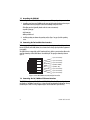
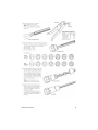
Model EHA3201
EnviroNET G.SHDSL Router
Quick Start Guide
Important—This is a Class A device and is intended for use in a light industrial environment. It is not
intended nor approved for use in an industrial or residential environment.
Part Number: 07MEHA3201-QS, Rev. B
Revised: July 21, 2011
Sales Office: +1 (301) 975-1000
Technical Support: +1 (301) 975-1007
E-mail: [email protected]
WWW: www.patton.com
WARNING
• Do not open the device when the power cord is connected. For systems without a power switch and without an external power
adapter, line voltages are present within the device when the power
cord is connected.
• For devices with an external power adapter, the power adapter shall
be a listed Limited Power Source The mains outlet that is utilized to
power the device shall be within 10 feet (3 meters) of the device,
shall be easily accessible, and protected by a circuit breaker in compliance with local regulatory requirements.
• For AC powered devices, ensure that the power cable used meets all
applicable standards for the country in which it is to be installed.
• For AC powered devices which have 3 conductor power plugs (L1, L2
& GND or Hot, Neutral & Safety/Protective Ground), the wall outlet
(or socket) must have an earth ground.
• For DC powered devices, ensure that the interconnecting cables are
rated for proper voltage, current, anticipated temperature, flammability, and mechanical serviceability.
• WAN, LAN & PSTN ports (connections) may have hazardous voltages
present regardless of whether the device is powered ON or OFF.
PSTN relates to interfaces such as telephone lines, FXS, FXO, DSL,
xDSL, T1, E1, ISDN, Voice, etc. These are known as “hazardous network voltages” and to avoid electric shock use caution when working
near these ports. When disconnecting cables for these ports, detach
the far end connection first.
• Do not work on the device or connect or disconnect cables during periods of lightning activity.
When the EHA3201 is mounted, it shall be secured in such a
way as to withstand a vertical shear force of 90N or 20lbs.
WARNING
In accordance with the requirements of council directive 2002/96/EC on
Waste of Electrical and Electronic Equipment (WEEE), ensure that at endof-life you separate this product from other waste and scrap and deliver
to the WEEE collection system in your country for recycling.
2
EHA3201 Quick Start Guide
Electrostatic Discharge (ESD) can damage equipment and impair electrical
circuitry. It occurs when electronic printed circuit cards are improperly
handled and can result in complete or intermittent failures. Do the following to prevent ESD:
WARNING
• Always follow ESD prevention procedures when removing and replacing cards.
• Wear an ESD-preventive wrist strap, ensuring that it makes good
skin contact. Connect the clip to an unpainted surface of the chassis
frame to safely channel unwanted ESD voltages to ground.
• To properly guard against ESD damage and shocks, the wrist strap
and cord must operate effectively. If no wrist strap is available,
ground yourself by touching the metal part of the chassis.
1.0 Installing the EHA3201
To install the EHA3201, follow these steps:
1. Make a ground connection for the unit (refer to section 1.1, “Grounding the EHA3201” on page 4).
2. Connect the line interface between the units (refer to section 1.2, “Connecting the Twisted-Pair Line Interface” on page 4)
Note See figure 1 for the EHA3201 unit’s bottom panel arrangements.
3. Connect the Ethernet interface (refer to section 1.3, “Connecting the 10/100Base-T Ethernet Interface”
on page 4).
4. Connect the power plug (refer to section 1.4, “Connecting Power” on page 5).
EnviroNET
EHA3201
En
vir
oN
ET
ª
TA
DA
E
LIN
R
WE
PO
Ethernet
port
Line twisted-pair
RJ-45 interface
Grounding Stud
Power
Figure 1. EHA3201 Bottom Panel
EHA3201 Quick Start Guide
3
1.1 Grounding the EHA3201
Before installing the EnviroNET G.SHDSL Router, it is important to establish a good grounding connection first.
1. Assemble a ground wire using #10 AWG wire with green-and-yellow-colored insulation and two ring terminals. Make the wire long enough to reach one of the following earth ground sources:
•The building ground rod (generally located at the site’s main service entrance)
•A sprinkler system pipe
•A cold-water pipe
•Building structural steel
2. Install the grounding wire between the grounding stud (see Figure 1 on page 3) and the grounding
source.
1.2 Connecting the Twisted-Pair Line Interface
To function properly, the G.SHDSL Router must be connected using twisted-pair, unconditioned, dry, metal wire,
between 19 (0.9mm) and 26 AWG (0.4mm). Leased circuits that run through signal equalization equipment are
not acceptable.
The G.SHDSL Router is equipped with an RJ-45 interface jack (Line), which is a two-wire interface. Observe the
signal/pin relationships on the G.SHDSL Router’s Line interface jack. The signal/pin relationship is shown in
figure 2.
1 (no connection)
1
2
3
4
5
6
7
8
2 (no connection)
3 (no connection)
4 (2-Wire RING)
5 (2-Wire TIP)
6 (no connection)
7 (no connection)
8 (no connection)
Figure 2. EnviroNET G.SHDSL Router (RJ-45) twisted pair line interface.
1.3 Connecting the 10/100Base-T Ethernet Interface
The G.SHDSL Router has an unshielded RJ-45 auto-MDIX10/100Base-T interface. This port is designed to connect directly to a 10/100Base-T network. figure 3 shows the signal/pin relationships on this interface. You may
connect this port to a hub or PC using a straight through or crossover cable that is up to 328 ft long.
4
EHA3201 Quick Start Guide
1 TX+ (data output from the G.SHDSL router)
1
2
3
4
5
6
7
8
2 TX- (data output from the G.SHDSL router)
3 RX+ (data input to the G.SHDSL router)
4 (no connection)
5 (no connection)
6 RX- (data input to the G.SHDSL router)
7 (no connection)
8 (no connection)
Figure 3. EnviroNET G.SHDSL Router 10/100Base-T RJ-45 Connector Pinout
1.4 Connecting Power
The EHA3201 is an internally powered unit. The power connection is made via the 3-pin power connector on the
bottom panel of the EnviroNET G.SHDSL Router. A mating connector is provided to create the mating cable (see
figure 4). No configuration is necessary for the power supply.
EHA3201/R/UI
L N
N
E
L = Line
N = Neutral
E = Earth
EHA3201/R/24
L
E
L = +24
N = Ground
L N
N
L
Figure 4. Connecting the power cable
The EnviroNET G.SHDSL Router does not have a power switch, so it powers up as soon as it is plugged in.
WARNING
EHA3201 Quick Start Guide
There are no user-serviceable parts in the EnviroNET G.SHDSL
Router. Fuse replacement should only be performed by qualified
service personnel. Contact Patton Electronics Technical support at
(301) 975-1007 for more information.
5
Note It does not matter whether the positive (+) or negative (-) side of the DC power supply is grounded.
However, the polarity on the power source must be matched up properly to the EHA3201 power input
(i.e. negative power source terminal to negative power input; positive power source terminal to positive
power input).
2.0 Configuring the EHA3201
The EnviroNET G.SHDSL Router comes pre-configured to communicate with other devices on the network. To
futher configure the EHA3201, you may log into the web management system.
2.1 Connect to a PC
1. Connect the EHA3201’s Data port to your PC (see figure 5).
2. The PC used for configuring the EHA3201 should be set for DHCP client.
3. Connect the EHA3201 to a power source to turn on the unit.
4. The EHA3201 Data port uses the DHCP client to automatically assign an IP address and netmask. The
EHA3201 will send the IP address to the PC.
5. Enter the EHA3201’s IP address in the address bar of the web browser.
6. Log in and perform any desired configuration changes through the EHA3201’s web browser interface.
En
v ir
oN
ET
PC
ª
DA
LIN
PO
WER
E
TA
Connect to
Ethernet port
(DATA)
Ethernet port
Figure 5. Connecting the EHA3201 to the local IP network
For information on changing the IP address, refer to Chapter 3 “Quick Start Installation” in the Model 3201 &
3241 User Manual.
6
EHA3201 Quick Start Guide
2.2 Configuring applications
The EHA3201 is typically used in a bridged or routed application. For instruction on how to configure the
EHA3201 for an application, refer to the Model 3201 & 3241 User Manual.
Bridged Applications
• For a bridged application connecting standalone units back-to-back, see pages 29-32 in the Model 3201 &
3241 User Manual.
• For a bridged application connecting the CPE to a DSLAM, see pages 38-46 in the Model 3201 & 3241 User
Manual.
Routed Applications
• For a routed application connecting standalone units back-to-back, see pages 32-38 in the Model 3201 &
3241 User Manual.
• For a routed application connecting the CPE to a DSLAM, see pages 46-77 in the Model 3201 & 3241 User
Manual.
3.0 Additional Information
Refer to the Model 3201 & 3241 User Manual located on the CD-ROM shipped with your EHA3201 and available
online at www.patton.com/manuals for detailed information about:
• Installing, configuring, operating, and troubleshooting,
• Warranty, trademark, & compliance
A.0 Customer and Technical Support
Toll-Free VoIP support: call sip:[email protected] with a VoIP SIP phone
Online support: www.patton.com
E-mail support: [email protected]—answered within 1 business day
Telephone support:
• Standard: +1 (301) 975-1007 (USA), Monday–Friday: 8:00 am to 5:00 pm EST (1300 to
2200 UTC/GMT)
• Alternate: +41 (0)31 985 25 55 (Switzerland), Monday–Friday: 8:00 am to 5:00 pm CET (0900 to 1800
UTC/GMT)
Fax: +1 (253) 663-5693 (USA) or +41 (0)31 985 25 26 (Switzerland)
EHA3201 Quick Start Guide
7
B.0 EHA Case Specifications
B.1 Power Requirements
• UAC: 110, 220VAC, 2.25W
B.2 Temperature Range
• -40–185°F (-40–85°C)
B.3 Humidity
• Up to 90% non-condensing.
B.4 Dimensions
• 8”H x 9.25”W x 3.25”D
B.5 Weight
• 6.4lb (2.9kg)
Note For Model 3201 unit specifications, refer to the Model 3201 & 3241 User Manual located on the CDROM shipped with your EHA3201 and available online at www.patton.com/manuals.
8
EHA3201 Quick Start Guide
C.0 Compliance Information
C.1 Compliance
EMC:
• FCC Part 15, Class A
• EN55022, Class A
• EN55024
Safety:
• UL 60950-1/CSA C22.2 N0. 60950-1
• IEC/EN60950-1
• AS/NZS 60950-1
PSTN Regulatory:
• FCC Part 68
• CS-03
• AS/ACIF S043:2003
C.2 FCC Part 68 (ACTA) Statement
This equipment complies with Part 68 of FCC rules and the requirements adopted by ACTA. On the bottom side of
this equipment is a label that contains—among other information—a product identifier in the format US:
AAAEQ##TXXXX. If requested, this number must be provided to the telephone company.
The method used to connect this equipment to the premises wiring and telephone network must comply with the
applicable FCC Part 68 rules and requirements adopted by the ACTA.
If this equipment causes harm to the telephone network, the telephone company will notify you in advance that
temporary discontinuance of service may be required. But if advance notice isn’t practical, the telephone company will notify the customer as soon as possible. Also, you will be advised of your right to file a complaint with
the FCC if you believe it is necessary.
The telephone company may make changes in its facilities, equipment, operations or procedures that could
affect the operation of the equipment. If this happens the telephone company will provide advance notice in
order for you to make necessary modifications to maintain uninterrupted service.
If trouble is experienced with this equipment, for repair or warranty information, please contact our company. If
the equipment is causing harm to the telephone network, the telephone company may request that you disconnect the equipment until the problem is resolved.
Connection to party line service is subject to state tariffs. Contact the state public utility commission, public service commission or corporation commission for information.
EHA3201 Quick Start Guide
9
3.3 Industry Canada Notice
This equipment meets the applicable Industry Canada Terminal Equipment Technical Specifications. This is confirmed by the registration number. The abbreviation, IC, before the registration number signifies that registration was performed based on a Declaration of Conformity indicating that Industry Canada technical specifications
were met. It does not imply that Industry Canada approved the equipment.
This Declaration of Conformity means that the equipment meets certain telecommunications network protective,
operational and safety requirements. The Department does not guarantee the equipment will operate to the
user's satisfaction. Before installing this equipment, users should ensure that it is permissible to be connected to
the facilities of the local telecommunications company. The equipment must also be installed using an acceptable
method of connection. In some cases, the company’s inside wiring associated with a single line individual service
may be extended by means of a certified connector assembly (telephone extension cord). The customer should
be aware that compliance with the above condition may not prevent degradation of service in some situations.
Repairs to some certified equipment should be made by an authorized maintenance facility designated by the
supplier. Any repairs or alterations made by the user to this equipment, or equipment malfunctions, may give
the telecommunications company cause to request the user to disconnect the equipment. Users should ensure for
their own protection that the ground connections of the power utility, telephone lines and internal metallic water
pipe system, are connected together. This protection may be particularly important in rural areas.
C.4 Radio and TV Interference (FCC Part 15)
This equipment generates and uses radio frequency energy, and if not installed and used properly—that is, in
strict accordance with the manufacturer's instructions—may cause interference to radio and television reception. This equipment has been tested and found to comply with the limits for a Class A computing device in accordance with the specifications in Subpart B of Part 15 of FCC rules, which are designed to provide reasonable
protection from such interference in a commercial installation. However, there is no guarantee that interference
will not occur in a particular installation. If the equipment causes interference to radio or television reception,
which can be determined by disconnecting the cables, try to correct the interference by one or more of the following measures: moving the computing equipment away from the receiver, re-orienting the receiving antenna,
and/or plugging the receiving equipment into a different AC outlet (such that the computing equipment and
receiver are on different branches).
10
EHA3201 Quick Start Guide
C.5 EC Declaration of Conformity
Product Description: Models 3201 & 3241
We certify that the apparatus identified above conforms to the requirements of Council Directive 1999/5/EC on
the approximation of the laws of the member states relating to Radio and Telecommunication Terminal Equipment and the mutual recognition of their conformity.
The safety advises in the documentation accompanying the products shall be obeyed. The
conformity to the above directive is indicated by the CE sign on the device.
The signed Declaration of Conformity can be downloaded from www.patton.com/certifications/.
C.6 Authorized European Representative
D R M Green
European Compliance Services Limited.
Oakdene House, Oak Road
Watchfield,
Swindon, Wilts SN6 8TD, UK
EHA3201 Quick Start Guide
11
Copyright statement
Copyright © 2011, Patton Electronics Company. All rights reserved.
The information in this document is subject to change without notice. Patton Electronics assumes no
liability for errors that may appear in this document.
Trademarks statement
The term EnviroNET is a trademark of Patton Electronics Company. All other trademarks presented in this document are the property of their respective owners.
Warranty, Trademark, & Compliance Information
For warranty, trademark and compliance information, refer to the Model 3201 & 3241 User Manual located on
the CD-ROM that came with your router or available online at www.patton.com.
12
EHA3201 Quick Start Guide
D.0 Buccaneer 400 Series Environmentally
Sealed Connectors
IMPORTANT
EHA3201 Quick Start Guide
The following instructions are provided by Bulgin UK for
assembling the 400 Series Buccaneer IP68 Sealed Electrical
Cable Connectors.
13
14
EHA3201 Quick Start Guide
EHA3201 Quick Start Guide
15
16
EHA3201 Quick Start Guide