1
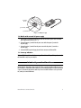
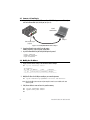
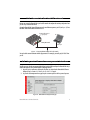
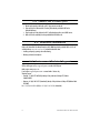
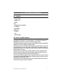
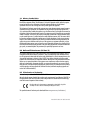
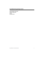
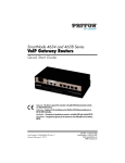
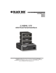
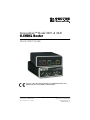
DiamondLink™ Model 3201 & 3241
G.SHDSL Router
Quick Start Guide
Important—This is a Class A device and is intended for use in a light industrial environment. It is not
intended nor approved for use in an industrial or residential environment.
Document Number: 03321U7-001 Rev. B
Part Number: 07M3201-QS
Revised: October 15, 2008
Sales Office: +1 (301) 975-1000
Technical Support: +1 (301) 975-1007
E-mail: [email protected]
WWW: www.patton.com
• This device contains no user serviceable parts. The equipment
shall be returned to Patton Electronics for repairs, or repaired
by qualified service personnel.
WARNING
• The external power adapter shall be a listed Limited Power
Source. The mains outlet that is utilized to power the devise
shall be within 10 feet (3 meters) of the device, shall be easily
accessible, and protected by a circuit breaker.
• If an AC power adapter is used, ensure that the power cable
used meets all applicable standards for the country in which it
is to be installed, and that it is connected to a wall outlet which
has earth ground.
• Hazardous network voltages are present in WAN ports regardless of whether power to the unit is ON or OFF. To avoid electric
shock, use caution when near WAN ports. When detaching the
cables, detach the end away from the device first.
• Do not work on the system or connect or disconnect cables
during periods of lightning activity.
1.0 Power up the router
The interconnecting cables shall be acceptable for external use and shall be rated for
the proper application with respect to voltage, current, anticipated temperature, flammability, and mechanical serviceability.
CAUTION
Your G.SHDSL router comes with one of the following power supply options:
• External AC adaptor with included power cord
• External DC power supply
1.1 Models with external AC adaptor
1. Connect female plug of the AC power cord to the AC adaptor provided.
2. Connect the barrel-type connector of the AC adaptor to the Power connector on the DiamondLink router.
3. Insert the male plug of the AC power cord into an AC power outlet (100–240 VAC).
2
DiamondLink 3201 & 3241 Quick Start Guide
Inpu
t:
36–6
( + (SE 0VDC
48V
, 0.
N/C LV)
DC
13A
P
-)
Out
Mod ower
put:
ule Sup
5V,
ply
1A
(C
tr +
)
I
n
p
ut:
36–
6
( + (SE 0VDC
, 0.
N/C LV)
13A
Po
-)
we
r
le Su
Terminal
block
(-) Terminal
(+) Terminal
Figure 1. 48VDC power supply
1.2 Models with external DC power supply
1. Strip insulation 1/4-inch from the electrical wires that will connect the DC power source to the 48VDC
power supply terminal block (see figure 1).
2. Connect the negative (-) terminal from the power source with to the negative (-) terminal on
the power supply.
3. Connect the positive (+) terminal from the power source with to the positive (+) terminal on
the power supply
4. Connect the 48VDC output barrel-type plug to the Power connector on the DiamondLink.
1.3 Power-up indication
The Power LED blinks as the DiamondLink is powering up. When the Power LED stops blinking and remains lit,
the DiamondLink is ready for you to configure.
2.0 Configure the IP address
The DiamondLink is shipped with a factory-configured IP address assigned to the Ethernet LAN port (green outline). The address is 192.168.200.10/24. In most cases, you must change the address to be on the same subnet
as your PC, as described in the procedures below. If you are not sure which IP address to use for your installation, contact your network administrator.
DiamondLink 3201 & 3241 Quick Start Guide
3
2.1 Connect a PC and log in
1. Using the included combination RS232/Ethernet cable and DB9-RJ45 adapter, connect a PC’s serial port
to the on the DiamondLink’s (red) Console port (see figure 2).
e
Lin
PC with
terminal emulator
et
ern
Eth
ole
I-X
MD
ns
Co
r
we
Po
Serial port
Connect to Console port
(red port)
Figure 2. Connecting DiamondLink to the PC’s serial port
2. Start a HyperTerminal session on the PC using the settings:
9600 bps, 8 data bits, 1 stop bit, no parity, no flow control
3. Log in to the DiamondLink using the factory-default login and password:
Login: superuser
Password: superuser
Login successful
2.2 Modify the IP address
1. Display current IP interface settings for the DiamondLink Ethernet LAN port.
→
ip list interfaces <enter>
IP Interfaces:
ID | Name | IP Address
| DHCP
| Transport
---|------|----------------|----------|-------------1 | ip1 | 192.168.200.10 | disabled | <bridge>
----------------------------------------------------
2. Modify the IP address for the LAN port according to your network requirements.
→
ip set interface ip1 ipaddress 10.10.10.5 255.255.255.0
Note The above IP address (10.10.10.5/24) is only an example. You must choose an IP address on the same
subnet as your PC.
3. Verify the new address is correct and save it in system boot memory.
→
→
→
4
ip list interfaces <enter>
system config save <enter>
DiamondLink 3201 & 3241 Quick Start Guide
3.0 Connect to the local IP network
Now you can connect the DiamondLink to your local IP network and complete the remaining configuration from
your PC using a standard web browser.
Connect the DiamondLink’s (green) Ethernet port to the same Ethernet segment as your PC (see figure 3). Press
the MDI-X switch until the Ethernet Link LED turns on.
Connect to Ethernet port
(green port)
PC
e
Lin
et
ern
Eth
ole
X
IMD
ns
Co
r
we
Po
MDI-X switch
Ethernet port
Figure 3. Connecting the DiamondLink to the local IP network
You can check the network connection with the ping command. For example, you would ping 10.10.10.5 from
your PC.
4.0 Log onto the web management interface
You will now access the web management Graphical User Interface (GUI) to configure the DiamondLink using a
standard web browser (such as Internet Explorer or Netscape browser).
1. At your PC, open a web browser and enter the IP address you assigned to the DiamondLink’s Ethernet
LAN port in step 2 of section 2.2 “Modify the IP address” on page 4.
2. Log in to the web management home page using the username superuser and the password superuser.
Figure 4. DiamondLink web management home page
DiamondLink 3201 & 3241 Quick Start Guide
5
5.0 Connect the G.SHDSL port
1. Obtain single-twisted-pair cable with an RJ-11 plug connector at each end.
2. Plug one end of the cable into the RJ-11socket (yellow colored port labeled LINE) on the
DiamondLink Router.
3. Plug the other end of the cable into the RJ-11 wall socket that provides your G.SHDSL service.
4. When a DSL link is established, the front panel WAN Link LED will turn on.
6.0 Additional Information
Refer to the DiamondLink User Manual located on the CD-ROM shipped with your Model 3201 or 3241 and
available online at www.patton.com/manuals for detailed information about:
• Installing, configuring, operating, and troubleshooting,
• Warranty, trademark, & compliance
A.0 Customer and Technical Support
Toll-Free VoIP support: call sip:[email protected] with a VoIP SIP phone
Online support: www.patton.com
E-mail support: [email protected]—answered within 1 business day
Telephone support:
• Standard: +1 (301) 975-1007 (USA), Monday–Friday: 8:00 am to 5:00 pm EST (1300 to
2200 UTC/GMT)
• Alternate: +41 (0)31 985 25 55 (Switzerland), Monday–Friday: 8:00 am to 5:00 pm CET (0900 to 1800
UTC/GMT)
Fax: +1 (253) 663-5693 (USA) or +41 (0)31 985 25 26 (Switzerland)
6
DiamondLink 3201 & 3241 Quick Start Guide
B.0 Compliance Information
B.1 Compliance
EMC:
• FCC Part 15, Class A
• EN55022, Class A
• EN55024
Safety:
• UL 60950-1/CSA C22.2 N0. 60950-1
• IEC/EN60950-1
• AS/NZS 60950-1
PSTN Regulatory:
• FCC Part 68
• CS-03
• AS/ACIF S043:2003
B.2 FCC Part 68 (ACTA) Statement
This equipment complies with Part 68 of FCC rules and the requirements adopted by ACTA. On the bottom side of
this equipment is a label that contains—among other information—a product identifier in the format US:
AAAEQ##TXXXX. If requested, this number must be provided to the telephone company.
The method used to connect this equipment to the premises wiring and telephone network must comply with the
applicable FCC Part 68 rules and requirements adopted by the ACTA.
If this equipment causes harm to the telephone network, the telephone company will notify you in advance that
temporary discontinuance of service may be required. But if advance notice isn’t practical, the telephone company will notify the customer as soon as possible. Also, you will be advised of your right to file a complaint with
the FCC if you believe it is necessary.
The telephone company may make changes in its facilities, equipment, operations or procedures that could
affect the operation of the equipment. If this happens the telephone company will provide advance notice in
order for you to make necessary modifications to maintain uninterrupted service.
If trouble is experienced with this equipment, for repair or warranty information, please contact our company. If
the equipment is causing harm to the telephone network, the telephone company may request that you disconnect the equipment until the problem is resolved.
Connection to party line service is subject to state tariffs. Contact the state public utility commission, public service commission or corporation commission for information.
DiamondLink 3201 & 3241 Quick Start Guide
7
2.3 Industry Canada Notice
This equipment meets the applicable Industry Canada Terminal Equipment Technical Specifications. This is confirmed by the registration number. The abbreviation, IC, before the registration number signifies that registration was performed based on a Declaration of Conformity indicating that Industry Canada technical
specifications were met. It does not imply that Industry Canada approved the equipment.
This Declaration of Conformity means that the equipment meets certain telecommunications network protective,
operational and safety requirements. The Department does not guarantee the equipment will operate to the
user's satisfaction. Before installing this equipment, users should ensure that it is permissible to be connected to
the facilities of the local telecommunications company. The equipment must also be installed using an acceptable
method of connection. In some cases, the company’s inside wiring associated with a single line individual service
may be extended by means of a certified connector assembly (telephone extension cord). The customer should
be aware that compliance with the above condition may not prevent degradation of service in some situations.
Repairs to some certified equipment should be made by an authorized maintenance facility designated by the
supplier. Any repairs or alterations made by the user to this equipment, or equipment malfunctions, may give
the telecommunications company cause to request the user to disconnect the equipment. Users should ensure for
their own protection that the ground connections of the power utility, telephone lines and internal metallic water
pipe system, are connected together. This protection may be particularly important in rural areas.
B.4 Radio and TV Interference (FCC Part 15)
This equipment generates and uses radio frequency energy, and if not installed and used properly—that is, in
strict accordance with the manufacturer's instructions—may cause interference to radio and television reception. This equipment has been tested and found to comply with the limits for a Class A computing device in accordance with the specifications in Subpart B of Part 15 of FCC rules, which are designed to provide reasonable
protection from such interference in a commercial installation. However, there is no guarantee that interference
will not occur in a particular installation. If the equipment causes interference to radio or television reception,
which can be determined by disconnecting the cables, try to correct the interference by one or more of the following measures: moving the computing equipment away from the receiver, re-orienting the receiving antenna,
and/or plugging the receiving equipment into a different AC outlet (such that the computing equipment and
receiver are on different branches).
B.5 EC Declaration of Conformity
Product Description: DiamondLink™ Models 3201 & 3241
We certify that the apparatus identified above conforms to the requirements of Council Directive 1999/5/EC on
the approximation of the laws of the member states relating to Radio and Telecommunication Terminal Equipment and the mutual recognition of their conformity.
The safety advises in the documentation accompanying the products shall be obeyed. The
conformity to the above directive is indicated by the CE sign on the device.
The signed Declaration of Conformity can be downloaded from www.patton.com/certifications/.
8
DiamondLink 3201 & 3241 Quick Start Guide
B.6 Authorized European Representative
D R M Green
European Compliance Services Limited.
Avalon House, Marcham Road
Abingdon,
Oxon OX14 1UD, UK
DiamondLink 3201 & 3241 Quick Start Guide
9
Copyright statement
Copyright © 2008, Patton Electronics Company. All rights reserved.
The information in this document is subject to change without notice. Patton Electronics assumes no
liability for errors that may appear in this document.
Trademarks statement
The term DiamondLink is a trademark of Patton Electronics Company. All other trademarks presented in this document are the property of their respective owners.
Warranty, Trademark, & Compliance Information
For warranty, trademark and compliance information, refer to the DiamondLink 3201 & 3241 User Manual
located on the CD-ROM that came with your router or available online at www.patton.com.
In accordance with the requirements of council directive 2002/96/EC on Waste of
Electrical and Electronic Equipment (WEEE), ensure that at end-of-life you separate
this product from other waste and scrap and deliver to the WEEE collection system in
your country for recycling.
10
DiamondLink 3201 & 3241 Quick Start Guide
DiamondLink 3201 & 3241 Quick Start Guide
11
12
DiamondLink 3201 & 3241 Quick Start Guide