1
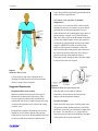
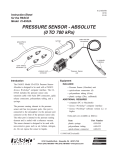
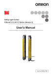
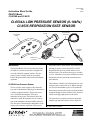
012-07034A
3/99
$1.00
Instruction Sheet for the
PASCO Model
CI-6534A and CI-6535
CI-6534A LOW PRESSURE SENSOR (0-10kPa)
CI-6535 RESPIRATION RATE SENSOR
cable with DIN
connectors
syringe
P D 10
R R
E
k
PA SS Y P
S C UR AI a M
C O E R
O N
A
PA N PO O X
R EC RT NL
T T M Y
N O A
O R T
. 6 : IN
40
G
-0
21
polyurethane
tubing
quick release
connectors (4)
to computer
interface
4A
53
-6
CI
W RE
LOSU R
S O
E
S
PR EN kPa)
S 10 E
G
0 - AU
(G
pressure port
connector
Introduction
The PASCO Model CI-6534A Low Pressure Sensor
(0-10kPa) is a pressure sensor that is designed to be
used with a PASCO computer interface. This low
pressure sensor is ideally suited for use with the
PASCO Respiration Belt or the PASCO Heat Engine
Apparatus.
CI-6534A Low Pressure Sensor
The low pressure sensor consists of the electronics
box with a cable that has a DIN plug for connecting to
a PASCO computer interface. The pressure sensor
uses a 10 kiloPascal transducer. This type of
transducer has two ports. The reference port of the
transducer is inside the electronics box. It is always
open to the atmosphere and not available to the user.
The other port is connected to the atmosphere via the
pressure port connector at the front of the pressure
Pressure Sensor
unit
sensor unit. It has a “quick-release” style connector for
attaching accessories such as the PASCO CI-6535
Respiration Belt accessory (which includes a Low
Pressure Sensor). The pressure sensor gives a reading
of “zero” when there is no pressure difference between
the internal reference port and the external pressure
port connector.
The transducer is durable, but it is designed to be used
with non corrosive gases such as air, helium, nitrogen,
etc. Do not let the transducer get wet. The maximum
short-term pressure that the sensor can tolerate without
permanent damage is about 100 kPa (14 psi). Please be
careful to not apply high pressure to the sensor.
The electronics box contains a precision operational
amplifier (op amp) that can drive a heavy capacitive
© 1999 PASCO scientific
Respiration Rate Sensor
012-07034A
ADDITIONAL REQUIRED
load, such as a six meter extender cable (CI-6515).
There is a resistor in parallel with the transducer to
compensate the sensor for temperature induced
variations. The sensor has a negative temperature
coefficient (resistance decreases as temperature
increases) and the resistor has a positive temperature
coefficient.
• computer (PC or Macintosh)
• Science Workshop® computer interface
• Science Workshop® software version 2.2 or
higher
ADDITIONAL RECOMMENDED
• Respiration Belt (PASCO part no. 003-05936,
included in the CI-6535 Respiration Rate
Sensor)
• Heat Engine/Gas Law Apparatus (PASCO
part no. TD-8572)
Extra parts are available as follows:
CI-6535 Respiration Rate Sensor
The CI-6535 Respiration Rate Sensor consists of
the CI-6534A Low Pressure Sensor and the
PASCO Respiration Belt (003-05936). See Figure
1.
PR DR10
ES
kP
PA
SU Y
SC CO RE AI a MA
O NN R
PA PO ON X
RT EC RT LY
TO
NO MA
R:
. 640 TIN
G
-02
1
Item
plastic syringe
polyurethane tubing
quick-release connector
Respiration Belt
Range and Resolution
4A
53
-6
CI
W RE
LOSU
ES OR
PR NSkPa)
SE10
0- AU
(G
The range of the CI-6534A Low Pressure Sensor is
between 0 and 10 kiloPascals. The resolution of the
sensor is 0.005 kiloPascals (kPa) when used with a
PASCO computer interface. The output voltage from
the sensor is +1.00 Volts when the pressure is 1
kiloPascal (kPa), and the output voltage is linear.
Therefore, the output voltage should be +10.00 Volts
at the top of the range (10 kPa). Atmospheric pressure
is normally around 101.326 kiloPascals (kPa).
Pressure can be measured in many different units (e.g.,
atmospheres, inches of mercury, millimeters of
mercury, kiloPascals, Bar, pounds per square inch).
Some equivalent values for pressure are:
GE
Figure 1
Respiration Rate Sensor
The belt has the following features:
• hook-and-pile strips sewn onto opposite ends of
the belt
• attached squeeze bulb for inflating the rubber
bladder inside the belt
• quick-release connector that can be attached to the
pressure port on the Low Pressure Sensor.
1 atmosphere = 30.00 in of Hg (at 16ºC)
= 760 millimeters of Hg
= 101.326 kiloPascals (kPa)
= 1.013 Bar = 1013 milliBar
= 14.696 pounds per square inch (psi)
Equipment
INCLUDED
•
•
•
•
Part Number
699-084
640-023
640-021
003-05936
Low Pressure Sensor (Gauge) unit
quick-release connectors (4)
polyurethane tubing (0.6m)
plastic syringe (20cc, calibrated)
2
012-07034A
Respiration Rate Sensor
Operation
5
1. Connect the Pressure Sensor unit to analog
channel A, B, or C of the Science Workshop
computer interface box using the cable with the
DIN connectors (Figure 2). Alternatively, the unit
can be plugged directly into the analog channel
jack.
tip
10
quick release
connector
Setting up the Equipment
barb
tubing
Figure 3
Using the syringe
To connect the syringe to the sensor, cut a short length
of tubing (about one inch). Put the “barb” end of one
of the quick-release connectors into one end of the
short piece of tubing. Put the other end of the tubing
over the tip on the end of the syringe.
Note: You can lubricate the end of the barb to make it
easier to put into the short piece of tubing. Put a very
small amount of silicon oil or saliva onto the barb
and then wipe the barb with a cloth so there is only a
thin layer of lubricant on the barb.
Align the quick-release connector with the pressure
port connector of the sensor. Push the connector onto
the port, and then turn the connector clockwise until it
“clicks” into place (less than one-eighth of a turn).
The barb of the quick-release connector is free to
rotate even when the connector is firmly attached to
the port. See Figure 4.
N U
0
(GA-10 SOR RE
UG kPa
E)
I-6
534
PR L
A
SE ESSOW
C
ES Y AI MAX
SU
R
PA CORE PO ON
SC NN RT LY
O PA EC MA
RT TOR: TIN
NO
G
. 64
0-0
21
PR
10
DR kPa
Figure 2
Connecting the amplifier box to the interface box
2. Connect the quick release connector to the
pressure port connector on the Pressure Sensor
unit.
The sensor is temperature compensated, therefore
changes in room temperature will not interfere with
the data.
quick release
connector
Push the connector onto the
pressure port. Turn
the connector
clockwise until it
“clicks” (less than
1/8 turn).
Using the Syringe and Quick-Release Connectors
The Pressure Sensor is designed for experiments such
as those that study the gas laws or for the rate of a
chemical reaction by monitoring the increase or
decrease in pressure. For example, Boyle’s Law is a
classic physics (and chemistry) concept that can be
demonstrated using the sensor and the syringe. See
Figure 3.
pressure port
connector
Figure 4
Using the quick release connectors
3
tubing
Respiration Rate Sensor
012-07034A
Mounting on an Experimental Apparatus
Use the 1/4-20 threaded connector located on the
bottom of the sensor box to secure the Pressure Sensor
to an experimental apparatus (Figure 5). The
alignment hole fits over an alignment pin included on
some PASCO apparatuses.
alignment hole
1/4-20 threaded
connector
Figure 5
Mounting connector and alignment hole
Using the Respiration Belt
To measure respiration rate (breaths per minute), place
the respiration belt around your chest or upper
abdomen, connect one tube from the belt to the low
pressure sensor, inflate the respiration belt with the
squeeze bulb, and monitor the respiration rate with the
computer interface.
Figure 6
Connecting the Respiration Belt, Right Side First
Placing the Respiration Belt
Inflating the Respiration Belt
Arrange the belt around your body so the part of the
belt that has the tubes on it is on the right side of
your body with the tubes hanging down from the
bottom edge of the belt.
Turn the knurled knob that is on the squeeze bulb fully
clockwise to close the release valve. Squeeze the bulb
several times to inflate the rubber bladder. You may
have to squeeze the bulb more than twenty times in
order to inflate the bladder. When the bladder is
inflated, the belt will be more snug against your chest.
Place the part of the belt that has the tubes against
your chest first. When this part is against your
chest, the strips of ‘pile’ should face away from
your chest. Then place the left side of the belt over
the first part so the hook-and-pile strips match each
other. The belt should be snug around the chest, but
not so tight that breathing is restricted. See Figure’s
6 and 7.
Warning: Over inflation can damage the air bladder.
Deflating the Respiration Belt
Turn the knurled knob on the squeeze belt
counterclockwise to open the release valve. Use your
hands to push the air out of the bladder. You can also
deflate the respiration belt by disconnecting the tube
from the pressure port on the sensor. Turn the quickrelease connector counterclockwise to disconnect it
from the pressure port.
Connecting the Belt to the Sensor
Align the quick-release connector on the end of one of
the respiration belt’s tubes with the pressure port
connector at the front of the pressure sensor unit.
4
012-07034A
Respiration Rate Sensor
Larger lung capacity and generally good health would
tend to decrease respiration rate.
Gay-Lussac’s Law (pressure vs. absolute
temperature)
Gay-Lussac’s Law states that if the volume remains
constant, the pressure of a container of gas is directly
proportional to its absolute temperature. Set up a
sealed container of air by attaching the longer piece of
plastic tubing to a stopper in a 125 mL Erlenmeyer
flask. Put a drop of glycerin on the bottom of one hole
of a two-hole rubber stopper. Put the glass part of an
eyedropper tip end up through one hole in the rubber
stopper. CAREFULLY put the end of the plastic
tubing over the tip of the eyedropper. Connect the
other end of the tube to the pressure port connector at
the front of the pressure sensor unit.. Put a drop of
glycerin on the top of the other hole. Insert a
temperature sensor through the hole. Place the stopper
in the top of the flask. See Figure 8.
Figure 7
Respiration Belt In Place
Lift up on the top flap of the respiration belt to
disengage the hook-and-pile strips from each other
when you want to remove the belt.
Figure 8
Experiment Setup For Gay-Lussac’s Law
Suggested Experiments
Respiration Rate versus Activity
Place the flask in water baths of different
temperatures. Record data on how the pressure
changes with the temperature changes.
Monitor respiration rate before and after exercise.
Measure the respiration rate while resting. Then
exercise vigorously. Measure the respiration rate
immediately after exercise, and the measure how long
it takes for the respiration rate to return to the resting
(“normal”) rate.
Pressure in Liquids
Put the end of the longer piece of tubing under water.
The pressure reading should increase by 0.0978 kPa
(0.02896 in of mercury) per centimeter of depth below
the surface. You can also use a “J” shaped tube to
study how pressure relates to the difference in heights
of the liquid in the two parts of the tube.
Respiration rate (number of breaths per unit of time)
depends on several factors: altitude, lung capacity,
health, and level of activity. Higher altitudes and levels
of activity would tend to increase respiration rate.
5
Respiration Rate Sensor
012-07034A
Studying Chemical Reactions by Monitoring
Pressure
DIN Connector Specifications
Many chemical reactions produce gases that can cause
an increase in pressure in a sealed container. The
pressure change can be used to monitor the rate of the
reaction.
2: analog output (-), signal ground
1: analog output (+), -10 to +10 V
3: (no connection)
6: +12 VDC power
Other
7: -12 VDC power
PASCO scientific also produces an Absolute Pressure
Sensor (Model CI-6532A), a Differential Pressure
Sensor (Model CI-6533) and a Barometer (Model CI6531A). The Absolute Pressure Sensor has a range
from 0 to 700 kiloPascals. The Differential Pressure
Sensor is similar to the CI-6532A, except that both
ports of the transducer are open to the atmosphere. It
is designed for experiments where pressure differs
from one part of the apparatus to another, such as in a
Venturi tube or for a demonstration of Bernoulli’s
principle. The Barometer has a range from 800 to
1100 milliBar (24 to 32 inches of mercury). It is
designed to be a reliable, accurate pressure sensor
for weather studies. It is temperature compensated
and has a voltage regulator, so changes in
temperature or changes in the computer’s power
supply will not interfere with the data.
6
1
8
1
5: power ground
P D 0
R R
E
k
PA SS Y P
S C UR AI a M
C
O ON E R A
PA N PO O X
R EC RT NL
T T M Y
N O A
O R T
. 6 : IN
40
G
-0
21
4: + 5 V DC power
7
3
5
4
2
8: (no connection)
Limited Warranty
PASCO scientific warrants the product to be free from
defects in materials and workmanship for a period of
one year from the date of shipment to the customer.
PASCO will repair or replace, at its option, any part of
the product which is deemed to be defective in
material or workmanship. The warranty does not cover
damage to the product caused by abuse or improper
use. Determination of whether a product failure is the
result of a manufacturing defect or improper use by
the customer shall be made solely by PASCO
scientific. Responsibility for the return of equipment
for warranty repair belongs to the customer.
Equipment must be properly packed to prevent
damage and shipped postage or freight prepaid.
(Damage caused by improper packing of the
equipment for return shipment will not be covered by
the warranty.) Shipping costs for returning the
equipment after repair will be paid by PASCO
scientific.
Note: This instruction sheet was written assuming that
the user has a basic familiarity with
Science Workshop and has access to the User’s
Guide for Science Workshop. Users can gain basic
skills by working through the tutorial within
Science Workshop. Another useful resource is the
Quick Reference Card for Science Workshop.
Address:
Phone:
FAX:
email:
web:
6
PASCO scientific
10101 Foothills Blvd.
Roseville, CA 95747-7100
(916) 786-3800
(916) 786-8905
[email protected]
www.pasco.com