1
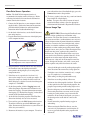
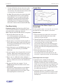
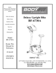
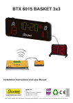
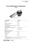
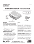
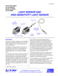
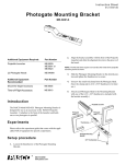
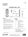
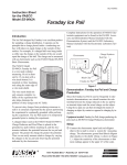
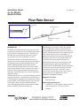
Instruction Sheet for the PASCO Model CI-6730A 012-08624A Flow Rate Sensor propeller Flow Rate Sensor propeller Close-up view of the propeller Introduction The PASCO CI-6730A Flow Rate Sensor measures flow rate in feet/sec (or meters/sec) and is designed for use with a PASCO 500 or 750 computer interface. The CI-6730A Flow Rate Sensor comes labeled with a metric/english measurement scale and is expandable to seven feet. The Flow Rate Sensor transforms the kinetic energy of moving water into electric pulses that can be converted into measurements and viewed in DataStudio software. The Model CI-6730A Flow Rate Sensor differs from the previous CI-6730 Flow Rate Sensor in that it uses a Hall effect sensing element instead of a magnetic reed switch. A Hall effect sensing element minimizes artifact pulses that sometimes occur with a magnetic reed switch, allowing for improved accuracy. The Flow Rate Sensor uses a removable turboprop propeller that rotates when only a small amount of water moves past it. The turboprop is mounted on a low-friction brass shaft, is protected inside a 2-inch diameter housing, and is designed to shed debris. There is no direct mechanical linkage between the turboprop and the sensing element that might interfere with the free movement of the prop. digital plug for computer interface The propeller has two magnets. When the propeller rotates, the Hall effect sensing element built into the housing of the Flow Rate Sensor generates an electrical impulse. The propeller makes 4.31 revolutions for each linear foot of water that passes, so 8.62 pulses are produced for each linear foot of water passing through the housing. Thus, the rate at which the impulses are generated is directly proportional to the flow rate. The Flow Rate Sensor feeds the electrical pulses into DataStudio through a digital port in the 500 or 750 computer interface. In DataStudio, the time between the electric pulses is measured and converted to velocity measurements (feet/second). Other units, such as nautical miles per hour (knots), meters per second, or miles per hour, may be defined by the user in DataStudio’s Experiment Calculator. Equipment included: • Flow Rate Sensor Additional Equipment Required: • A PASCO ScienceWorkshop® computer interface [500 (for outdoors) or 750 (for classroom)] • Computer Flow Rate Sensor 012-08624A Flow Rate Sensor Operation your collected data into a DataStudio display, press the Connect button on the Setup toolbar. ➤Note: The PASCO 500 computer interface is recommended for outdoor studies of flow rate. Before collecting data in the field, ensure that the 500 interface contains four fresh AA batteries. 10. To view a graph of a data run, drag a run icon from the Data window to a Graph display. ➤Note: To express the velocity in terms of meters/ second, miles/hour, or knots, create the appropriate calculation in the DataStudio’s Experiment Calculator. 1. Connect the 500 interface to your computer with the supplied cables. (Follow the connections instructions provided with the 500 interface and/or installation instructions in the DataStudio online help.) Sensor Usage Tips 2. On the back of the interface, use the On/Off button to turn on the interface. SAFETY TIPS: When using the Flow Rate Sensor outdoors, follow standard water and outdoor safety precautions. The Flow Rate Sensor is recommended for use in streams and lakes (avoid turbulent waters or rivers). Always inform students of potential hazardous conditions in the area. Do not use the sensor in high winds, adverse weather or avalanche conditions, near potential land or mudslides, or when standing on unstable ground. Before using the sensor, survey the area. When inserting the Flow Rate Sensor into water, stand on stable ground or in shallow water. Keep the Flow Rate Sensor away from water that has lots of debris or potential obstacles. If the propeller or sensor becomes lodged in a high velocity current or near a drop off, do not attempt to remove the sensor. In high risk situations, only allow a water patrol officer or public safety official to remove the sensor. 3. Plug the Flow Rate Sensor into one of the digital ports of the computer interface. ScienceWorkshop RES 1 ® Interface T L O A s ANALOG CHANNELS B n C 2 G S P 500 O DIGITAL CHANNELS ON GAIN=1,10:ISOLATED GAIN = 1,10: REF TO GND GAIN = 1: REF TO GND Plug into a digital channel port Figure 1: Inserting the Flow Rate Sensor’s digital plug into a digital port on the computer interface 4. Start DataStudio. From the Sensors list, drag and drop the Flow Rate icon to the digital port icon that corresponds to the digital port you are using on the computer interface. • • 5. If the flow rate is expected to be less than 1 ft./s, decrease the sample rate to 2 seconds per sample. (To change the sample rate, double click the sensor icon. In the dialog box, select the General tab and change the sample rate. Click OK.) 6. On the Setup toolbar, click the Logging button and follow the prompts. Disconnect the 500 interface for remote data logging. (For more information on remote data logging, see “Remote Data Logging” in the table of contents of the DataStudio online help.) • When taking a reading, keep the handle steady. • If the flow rate reading suddenly falls to zero midstream, check the propeller for debris. When sand or other particles become lodged in the propeller, the propeller stops turning and the reading drops to zero. • Erratic readings may occur with turbulent water flow. If measuring flow from a stream or creek, keep the housing in a stable position, away from rocks and turbulence. If measuring in low depths, you can rest the housing on the stream bed for a more stable reading. Do not connect the propeller housing to pipes or other tubing. 7. At the field site: Insert the propeller of the Flow Rate Sensor into the body of water to be measured. • 8. To record data, press the LOG button on the interface. To end data collection, press the LOG button again. (Note: Do not turn off your interface or you will lose all of the data you recorded.) • 9. Reconnect the interface to your computer. To retrieve 2 Always hold the pole vertically and keep the propeller in the direction of the current flow, facing upstream. For higher water velocities (around >1 m/s), a sample rate of 2 samples/sec is recommended. When not using the Flow Rate Sensor, store the sensor in a dry environment to avoid corrosion. If necessary, periodically lubricate the propeller with silicone oil. 012-08624A • Flow Rate Sensor Sample Data If using the Flow Rate Sensor from a boat, tether the boat such that the boat does not move during measurements. Boat movement may interfere with an accurate flow rate measurement. ➤ Note: The instruction sheet has been written with the assumption that the user has a basic familiarity with DataStudio. Users can gain basic skills with DataStudio by doing the tutorial in the DataStudio CD-ROM. For more information on datalogging with the 500 interface, see “Remote Data Logging” in the table of contents of the DataStudio online help. Determining Total Water Output in a Stream Bed Flow Rate Activity Equipment required: Flow Rate Sensor (CI-6730A), ScienceWorkshop 500 interface, DataStudio software, a set of four AA batteries, pad of paper and pencil Use the equation, output = average flow rate x area to determine the total water output in a stream bed. Note: Calibration of the Flow Rate Sensor is not required. Field Procedure: 1. Plug the Flow Rate Sensor into a 500 ScienceWorkshop interface and set up your experiment in DataStudio; then disconnect the 500 interface from your computer. 1. With a measuring tape or other device, measure the width of the steam bed. Record the stream width (in meters) on a piece of paper. 2. With the Flow Sensor measurement scale, take depth measurements (in meters) at equally spaced intervals across the stream. (For an accurate depth measurement, submerge the sensor until the propeller housing rests on the bottom of the stream bed. Keep the pole vertical.) Record each depth measurement on a piece of paper. 2. Near the shore of a stream bed, insert the propeller of the Flow Rate Sensor about 2 inches below the surface of a moving stream. Hold the pole vertically and keep the propeller housing steady. 3. On the 500 interface, press the LOG button to take a reading. To end data collection, press the LOG button again. 3. With the Flow Rate Sensor connected to a 500 ScienceWorkshop interface, take a flow rate measurement (in m/s) for each of the intervals. (Be sure to take a separate data run for each measurement.) 4. On a piece of paper, draw a diagram of the stream and shoreline. With a pencil, mark a point on the stream diagram to indicate where you took the measurement. 5. Repeat steps 2-4 at different locations and depths as follows: a) near the shoreline at one foot b) midstream at one foot c) midstream at two feet and d) midstream at three feet. Estimating the total water output: 1. Calculate the cross-sectional area of the stream: Multiply each interval width by each depth you measured to calculate the area for each interval; then add the areas for each of the intervals to obtain the total cross-sectional area of the stream. (Note: The more intervals you use, the closer your approximation of the area will be to the actual area.) 6. Reconnect the 500 to your computer. Use the Connect button on the main toolbar to retrieve data into DataStudio. 7. In DataStudio, compare the flow rate at the different depth increments and/or different locations. Is the flow rate higher midstream or near the shore? What effect might depth have on the flow rate? 2. Connect the interface to your computer. Open DataStudio and retrieve your flow rate data for each of the intervals. Average the flow rate recorded for each of the intervals. 3 Flow Rate Sensor 012-08624A Warranty 3. To determine the total water output for a given flow rate, multiply the average flow rate by the total crosssectional area of the stream bed. For a description of the product warranty, see the PASCO catalog. Address: stream width interval Phone: FAX: Email: Web: Figure 2: Measuring the cross-sectional area of a stream bed. Flow Rate Sensor Specifications Range: 0.3–13 ft./s (0.1–4 m/s) Accuracy: 0.1 ft./s Minimum depth: 1.5 in (3.8 cm) Sensor type: Protected turboprop propeller with electromagnetic pickup Length: 3-7 feet with telescoping tube Materials: PVC housing, fitting and handle, anodized aluminum tube, and brass propeller bearing 4 PASCO scientific 10101 Foothills Blvd. P.O. Box 619011 Roseville, CA 95678-9011 (916) 786-3800 (916) 786-8905 [email protected] www.pasco.com