1
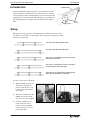
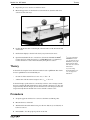
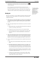
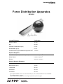
I n s tr uc t io n Ma n ua l
012- 09074A
Force Distribution Apparatus
ME-8092
Included Equipment
Part Number
Aluminum Beam
ME-8092
Ball
ME-8092
Captured Thumbscrews (qty. 3)
613-099
Hex Standoffs (qty. 3)
615-245
CD-ROM containing DataStudio Configuration Files1
576-09338
Required Equipment
Force Sensors (two required, third optional)
PS-2104 or equivalent2
Motion Sensor
PS-2103 or equivalent2
Balance
SE-8775A or equivalent
Required Mounting Equipment3
Table Clamps (qty. 2)
ME-9472
Multi Clamps (qty. 2)
SE-9442
120 cm Rod
ME-8741
90 cm Rod
ME-8738
45 cm Rod
ME-8736
1 Files
require DataStudio version 1.9.5 or later. Visit www.pasco.com to download the latest version of DataStudio.
“Equipment Notes” on page 5.
3 May be replaced with any equipment for mounting the apparatus as pictured on page 3.
2 See
®
Fo r c e Di s t r ib u ti o n A pp a r at us
Intr oduction
Introduction
Aluminum Beam
The Force Distribution Apparatus allows you to study the forces and
torques exerted on a stationary beam as a ball rolls along it. A motion
sensor tracks the position of the ball and two force sensors measure the
supporting forces. As the position of the ball changes, you will discover
how the supporting forces change to keep the beam in static equilibrium.
Force
Sensors
Support Rod
Setup
The beam has five tapped holes, or mounting points, to which force sensors can be
attached: two outer points, two inner points, and a central point. Some typical configurations are shown below.
Two sensors attached at the inner points
Two sensors attached at the outer points
Two sensors, one attached at an outer point and one
attached at an inner point
Two sensors, one attached at an inner or outer point,
the other attached at the central point
Three sensors, one attached at the central point, the
others attached at the inner or outer points
To attach a force sensor to the beam:
2
1.
Thread a thumbscrew into one
of the beam’s tapped holes.
Screw it all the way in so it is
loosely captured as pictured
(near right).
2.
Thread a hex standoff onto the
thumbscrew. Screw it all the
way in so it is loosely captured.
3.
If a hook or bumper is connected to the force sensor,
remove it. Screw the thumbscrew into the force sensor as
pictured (far right).
®
Mo d el No . M E- 8 0 92
4.
Repeat the process to attach a second force sensor.
5.
Mount the apparatus on a horizontal rod as shown below. (Note that both force
sensors face the same way.)
6.
Position the motion sensor at the height of the ball and 15 to 20 cm from the end
of the beam.
7.
Incline beam slightly so the ball rolls slowly away from motion sensor.
8.
Open the DataStudio file Force Distribution.ds from the included CD-ROM.1
Connect the force and motion sensors to a PASPORT interface (or interfaces).
Connect the left force sensor first followed by the right force sensor.2
Theory
As the ball rolls along the beam, the beam remains in static equilibrium. The criteria
for static equilibrium of an extended body are
•
the sum of all the external forces is zero: F net = ΣF = 0
•
and the sum of all the external torques is zero: τ net = Στ = 0
T he o r y
1
If you are using three
PASPORT force sensors, open the file Force
Distribution (3 force).ds.
Connect the left, right,
and center force sensors
in that order.
2
If you are using
ScienceWorkshop sensors, see page 5 for
instructions.
As the ball changes position, the force exerted by each force sensor changes, but the
net force exerted by the ball and both force sensors remains constant at zero. Also, the
torque exerted by the ball changes (because the ball’s lever arm changes), but the net
torque exerted by the ball and both force sensors remains constant at zero.
Procedure
1.
Set up the apparatus with two force sensors at the inner attachment points.
2.
Measure the mass of the ball.
3.
With the ball removed from the beam, press the zero buttons (or tare buttons) on
both force sensors.
4.
In DataStudio, view the graph of position versus time
®
3
Fo r c e Di s t r ib u ti o n A pp a r at us
5.
Procedur e
Place the ball at the end of the beam closest to the motion sensor. Click
.
Allow the ball to roll along the beam away from the motion sensor. Catch the ball
as it rolls off the end.
Data recording will start when the ball is 0.2 m from the motion sensor.
Recording will stop when it reaches 1.1 m (just before the end of the track).3
If necessary, adjust the angle and position of the motion sensor and repeat data
collection in order to obtain a smooth, continuous position versus time graph.
Analysis
3
To adjust the delayed
start and automatic stop
parameters, click the
Setup button in
DataStudio’s main tool
bar; the Experiment
Setup window will open.
Click the Sampling
Options button.
Because you zeroed the force sensors with the beam mounted on them, the weight of
the beam is not part of the recorded force data. For this analysis, treat the beam as
though it were massless.
1.
Observe the force versus position graph for one of the force sensors. Why is the
force positive in one part of the graph and negative in the other part? When the
force changes from positive to negative (or from negative to positive), where is
the ball?
2.
Observe the graph showing the sum of measured forces (total force) versus ball
position.
a.
How does the total force vary as the ball rolls along the beam? (Consider any
variation as a percentage of the total force).
b.
Compare the average value of the total force to the weight of the ball.
c.
List all of the objects that exert force on the beam. For any position of the
ball, what is the net force on the beam? (Remember to treat the beam as
massless.)
3.
Observe the table showing the position of the ball measured by the motion sensor
and the forces measured by both force sensors. Using only this data, determine
the distance from the motion sensor to each force sensor. (Hint: when the ball is
directly over one force sensor, the reading from the other force sensor is zero.)
4.
Choose a point in the data table where the ball was somewhere between the force
sensors.
a.
What is the position of the ball and the readings of both force sensors at that
point?
b.
The formula for the torque, τ, exerted by an object is τ = rF, where r is the
lever arm (or distance from the motion sensor to the object) and F is the
force exerted by the object. Since all distances are measured from the motion
sensor, this formula gives the torque about the position of the motion sensor.
Calculate the torque exerted on the beam by each object that interacts with it.
Don't forget to include the torque applied by the ball. Why do you not need
to consider the weight of the beam?
c.
4
Calculate the total torque that tends to rotate the beam clockwise and the
total torque that tends to rotate the beam counter-clockwise. How do they
compare? What is the net torque on the beam?
®
Mo d el No . M E- 8 0 92
E qu i p me n t N ot e s
Further Study
1.
Repeat the torque calculation, but measure the lever arms from a different point
(for instance, one end of the channel). How does the net torque change?
2.
Repeat the torque calculation for a point in the recorded data where the ball is on
the same side of both force sensors.
3.
Repeat the entire experiment with the force sensors attached to the beam at different points.
4.
Repeat the experiment, but press the zero buttons on the force sensors before
attaching the beam. Measure the mass of beam and include it in the force and
torque calculations.
5.
Repeat the experiment with the beam mounted on three force sensors.
Equipment Notes
PASPORT Interfaces
The recommended PASPORT Force Sensors and Motion Sensor require a PASPORT
interface or interfaces with a total of three ports (or four ports if three force sensors
will be used). Multiple PASPORT interfaces in any combination can be used to make
up the required number of ports.
ScienceWorkshop Sensors
PASPORT
Interface
No.
of
Ports
Xplorer GLX
4
PowerLink
3
Xplorer
1
USB Link
1
A ScienceWorkshop Motion Sensor (CI-6742) and Force Sensors (CI-6537 or
CI-6746) can be used instead of PASPORT sensors. Open the DataStudio configuration file SW Force Distribution.ds for two force sensors or SW Force Distribution (3
force).ds for three force sensors.
•
If you are using a ScienceWorkshop interface, connect the motion sensor to
Channels 1 and 2; connect the left force sensor to Channel A, the right force sensor to Channel B, and the center force sensor (if used) to Channel C.
•
If you are using a Digital Adapter (PS-2159) and Analog Adapters (PS-2158)
with ScienceWorkshop sensors, connect the adapters for the left, right, and center
force sensors to the PASPORT interface (or interfaces) in that order.
®
5
Fo r c e Di s t r ib u ti o n A pp a r at us
S am p l e D at a
Sample Data
The graphs above are Position vs. time as ball rolls (left), the forces measured by each
sensor versus ball position (center), and the sum of the measured forces versus ball
position (right). When the ball is not between the sensors, the force measured by one
of the sensors is negative. The sum of the measured forces equals the weight of the
ball. The weight of the beam was zeroed out and does not contribute to the measured
forces.
The table below on the left shows that the left sensor is 0.88 m from the motion sensor
and the right table shows that the right sensor is 0.38 m from the motion sensor.
In this example, the point chosen for analysis is where the ball
was 0.498 m from the motion sensor. This gives the values of
F left = 1.7 N
τleft = rF = (0.88 m)(1.7 N) = 1.5 N·m
F right = 5.3 N
τright = (0.380 m)(5.3 N) = 2.0 N·m
τ ball = (0.50 m)(7.0 N) = 3.5 N·m
Note that the weight of the ball tends to make the beam rotate counterclockwise (as
measured from the motion sensor) but the two force sensors tends to make it rotate
clockwise.
Total clockwise torque = 1.5 N·m + 2.0 N·m = 3.5 N·m
Total counterclockwise torque = 3.5 N·m
Since these two torques are in opposite directions, they have opposite signs, thus the
total net torque is zero.
6
®
Mo d el No . M E- 8 0 92
S p ec i f ic a t io n s
Specifications
Beam Length
95 cm
Ball Mass
Approx. 0.7 kg
Technical Support
For assistance with any PASCO product, contact PASCO at:
Address:
PASCO scientific
10101 Foothills Blvd.
Roseville, CA 95747-7100
Phone:
916-786-3800 (worldwide)
800-772-8700 (U.S.)
Fax:
(916) 786-3292
Web:
www.pasco.com
Email:
[email protected]
Limited Warranty
For a description of the product warranty, see the PASCO catalog.
Copyright
The PASCO scientific 012-09074A Force Distribution Apparatus Instruction Manual is copyrighted with all rights reserved. Permission
is granted to non-profit educational institutions for reproduction of any part of this manual, providing the reproductions are used only
in their laboratories and classrooms, and are not sold for profit. Reproduction under any other circumstances, without the written consent of PASCO scientific, is prohibited.
Trademarks
PASCO, PASCO scientific, DataStudio, PASPORT, ScienceWorkshop, Xplorer and Xplorer GLX are trademarks or registered trademarks of PASCO scientific, in the United States and/or in other countries. All other brands, products, or service names are or may be
trademarks or service marks of, and are used to identify, products or services of, their respective owners. For more information visit
www.pasco.com/legal.
Author: Jon Hanks
Editor: Alec Ogston
®
7