1
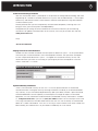
IMPORTANT SAFETY INSTRUCTIONS
The lightning flash with the arrowhead symbol within an equilateral triangle is intended to alert the user
to the presence of “dangerous voltage” inside the product that may constitute a risk of electric shock.
The exclamation point within an equilateral triangle is intended to alert the user to the presence
of important operating and maintenance instructions in the literature accompanying the product.
TO REDUCE THE RISK OF ELECTRIC SHOCK, DO NOT REMOVE COVER. NO USER-SERVICEABLE
PARTS INSIDE. REFER SERVICING TO QUALIFIED SERVICE PERSONNEL
1.
Read Instructions — Read all the safety and operating instructions before operating this product.
2.
Retain Instructions — Retain safety and operating instructions for future reference.
3.
Heed Warnings — Adhere to all warnings on the product and in the operating instructions.
4.
Follow Instructions — Follow all operating and use instructions.
5.
Cleaning — Unplug this product from the wall outlet before cleaning. Use a damp cloth for cleaning.
Clean the outside of the product only.
6.
Attachments — Do not use attachments that are not recommended by the product manufacturer;
they may be hazardous.
7.
Water and Moisture — Do not use this product near water.
8.
Accessories — Do not place this product on an unstable cart or stand. The product may fall, causing
bodily injury and damage to the product. A product and cart combination should be moved with care.
Quick stops, excessive force, and uneven surfaces may cause the product and cart to overturn.
9.
Ventilation — Slots and openings in the cabinet are provided for ventilation to ensure reliable operation of
the product and to protect it from overheating. These openings must not be blocked or covered. This product
should not be placed in a built-in installation such as a bookcase or rack unless proper ventilation is provided.
10. Power Sources — Operate this product only from the type of power source indicated on the label.
If you are not sure of the type of power supply to your home, consult your dealer or local power
company. This product is equipped with a three-prong grounding plug. This plug will only fit into a
grounding power outlet. If you are unable to insert the plug into the outlet, contact your electrician
to replace your obsolete outlet. Do not defeat the safety purpose of the grounding plug.
11. Power Cord Protection — Power supply cords should be routed so that they are not likely to be
walked on or pinched by items placed upon or against them.
12. Lightning — Unplug the unit from the wall outlet for added protection during a lightning storm
and when it is left unattended and unused for long periods of time. This will prevent damage to the
product due to lightning and power line surges.
13. Overloading — Do not overload wall outlets or extension cords. This can result in a fire or electric shock.
14. Inserting Objects into Unit — Never push objects of any kind into this product through any openings;
they may touch dangerous voltage points or short out parts that could result in fire or electric shock.
15. Servicing — Do not attempt to repair or service this product yourself. Opening or removing covers may
expose you to dangerous voltage and other hazards. Refer all servicing to qualified service personnel.
16. Damage Requiring Service — Unplug this product from the wall outlet and refer servicing to qualified
service personnel under the following conditions: a) If the power-supply cord or plug is damaged.
b) If liquid has been spilled into the product. c) If the product has been exposed to rain or water. d)
If the product does not operate normally by following the operating instructions. e) If the product has
been dropped or damaged in any way. f) If the product exhibits a distinct change in performance.
17. Replacement Parts — When replacement parts are required, be sure the service technician has used
replacement parts specified by the manufacturer. Unauthorized substitutions may result in fire, electric
shock, and other hazards.
18. Safety Check — Upon completion of any service or repairs to this product, ask the service technician
to perform safety checks to determine that the product is in proper operating condition.
19. Wall or Ceiling Mounting — Mount the product to a wall or ceiling only as recommended.
20. Heat — The product should be situated away from heat sources such as radiators, heat registers,
stoves, and other products (including amplifiers) that produce heat.
www.parasound.com
INTRODUCTION
3
Thank You for Choosing Parasound
Your new Parasound® Halo P 7 preamplifier is the pinnacle of analog audio technology and value
engineering for a stereo or surround sound music system. We’ve endowed the P 7 with unique
connectivity and control features which enable it to be the centerpiece of a high-end stereo or
surround sound system.
We are proud to offer you this exceptionally versatile audio component, knowing that it will
bring you many years of enjoyment and dependability.
We appreciate you taking the time to read these instructions and thank you for selecting
Parasound. For updates and corrections to this manual, we invite you to check our web site,
www.parasound.com
Enjoy.
The Parasound Staff
Keeping Records for Future Reference
Record the serial number located on the back panel or bottom of your P 7 in the space below.
Also note your Parasound Dealer’s name and telephone number. Your purchase receipt/bill
of sale is required to determine if your P 7 is eligible for Parasound warranty service. We
recommend that you make an extra copy of your original purchase receipt/bill of sale and
store it inside the P 7’s carton.
OWNERSHIP REFERENCE INFORMATION
Parasound P 7 Preamplifier Serial #:
Parasound Dealer:
Dealer Phone Number:
(
)
-
Date of Purchase:
/
/
Important Warranty Information
There is no Parasound warranty for this unit if it was not purchased from an Authorized
Parasound Dealer. Investigate warranty coverage statements made by an unauthorized dealer
very carefully, as you will need to depend entirely upon your dealer, and NOT upon Parasound.
Unauthorized dealers lack the capability to make repairs or arrange for repairs of Parasound
equipment. A list of Authorized Parasound Dealers and detailed warranty information is available
at www.parasound.com or you can call (415) 397-7100 between 8:30 am and 4 pm Pacific time.
A missing or altered serial number could indicate that this unit was re-sold by an unauthorized
dealer or is stolen merchandise. If this unit is missing its serial number or the serial number has
been altered, you should return it to your dealer immediately for a full refund.
4
TABLE OF CONTENTS
Important Safety Instructions .
Introduction
. . . . . . . . . . . . . . . . . . . . . . . . . . . . . . . . . . . . . . .
2
. . . . . . . . . . . . . . . . . . . . . . . . . . . . . . . . . . . . . . . . . . . . . . . . . . .
3
Placement and Ventilation Guidelines .
Audio Input Connections .
. . . . . . . . . . . . . . . . . . . . . . . . . . . . . . . . .
5
. . . . . . . . . . . . . . . . . . . . . . . . . . . . . . . . . . . . . . . . . .
6
Audio Output Connections .
. . . . . . . . . . . . . . . . . . . . . . . . . . . . . . . . . . . . . . . . .
Other Connections on your P 7
. . . . . . . . . . . . . . . . . . . . . . . . . . . . . . . . . . . . . .
Using the Bypass Mode With a Surround Receiver.
11
. . . . . . . . . . . . . . . . . . . . . . . . . . . . . . .
14
. . . . . . . . . . . . . . . . . . . . . . . . . . . . . . . . . . . . . . . . . . .
20
Remote Control Operation
. . . . . . . . . . . . . . . . . . . . . . . . . . . . . . . . . . . . . . . . .
Frequently Asked Questions.
. . . . . . . . . . . . . . . . . . . . . . . . . . . . . . . . . . . . . . .
If You Require Assistance or Warranty Repair .
Specifications .
10
. . . . . . . . . . . . . . . . . . . . . . . .
Making Adjustments in the Setup Menu .
Front Panel Operation .
8
21
23
. . . . . . . . . . . . . . . . . . . . . . . . . . .
25
. . . . . . . . . . . . . . . . . . . . . . . . . . . . . . . . . . . . . . . . . . . . . . . .
26
UNPACKING YOUR P 7 AND PLACEMENT GUIDLINES
Unpacking Your P 7
Carefully remove your P 7 from its shipping carton and locate all the enclosed accessories:
•
Remote control and two AAA batteries
•
AC power cord
•
Stereo 3.5mm cable for front panel MP3 input
•
Four trigger wires, two with 2.5 mm sub-mini plugs, two with a 2.5mm and a 3.5mm mini plug
While you are unpacking your P 7, inspect it thoroughly for possible shipping damage and tell your
Parasound dealer immediately if you find any. If possible, save and store both the inner and outer
cartons and—most especially—the foam packing inserts, to protect the P 7 if you have to move it
or ship it. You may wish to flatten the cardboard cartons to save room in storage after cutting the
taped seams on the bottom flaps. This would be a good time to make a copy of your sales receipt
to store with the P 7’s original packing.
Placement Guidelines
The P 7 will be easier to use and will last longer if you follow these simple guidelines:
•
Place the P 7 on a shelf that will adequately support its weight.
•
Unless you’ll control the P 7 through a remote infrared sensor/repeater system, put it on a shelf
where you can aim the remote control handset directly at the P 7. (If you use a remote repeater
sensor, be sure the remote handset’s signals can’t reach the P 7’s front panel IR remote sensor,
otherwise the remote control might not function properly).
If you’re installing the P 7 yourself, use input and output cables that are long enough to leave at
least two feet of slack; that will enable you to pull the P 7 out of a cabinet to check or to change
connections without inadvertently disconnecting cables. If you’re putting the P 7 in a cabinet, it
needs a space that’s at least 22 inches wide so you’ll be able to turn it around for access to its rear
panel connections.
Ventilation Requirements
To reduce the chances of your P 7 overheating please follow these guidelines:
•
Install your P 7 away from heat sources such as heating ducts, radiators, or heat-producing
electronics.
•
Always position the P 7 horizontally.
•
We do not recommend placing the P7 directly on top of a power amplifier because this could
cause both components to overheat.
•
Do not install the P 7 in an unventilated equipment cabinet or compartment. Pockets of stagnant
hot air can build up even in cabinets with open front and back sides. A ventilation fan such as the
Parasound Zbreeze is highly recommended to prevent “hot spots” in confined spaces.
Rack Mounting Your Parasound P 7
With its four feet removed, the P 7’s front panel height occupies two rack spaces: 3.5” or
88.2 mm. (A single standard rack space occupies 1.75” vertical space.) For mounting in a
standard 19” equipment rack, you must use the Parasound HRA 2 rack mount kit (purchased
separately). The HRA 2 kit includes four bolts and eight plastic washers with raised “shoulders.”
Slide one washer onto each mounting bolt with its raised shoulder pointing toward the panel hole.
Carefully insert the bolt through the hole and slide the other washer on the bolt with its raised
shoulder facing the rear side of the panel. The washers will sandwich the P 7 panel and the four
mounting bolts to prevent metal-to-metal contact between the P 7 chassis, the equipment rack,
and the other components mounted in the rack.
Note: Tighten each bolt just enough to keep the unit secure in the rack to avoid deforming the
shoulder washers. Eliminating metal-to-metal contact reduces the likelihood of creating a ground
loop that might introduce hum into your system.
5
6
CONNECTING YOUR P 7
Always disconnect the AC cords to your P 7 and power amplifier(s) before making or
changing any input, output or trigger wire connections. Inserting or removing an input or
output cable while the P 7 or power amplifiers are turned on can result in a blast of sound that can
damage your loudspeakers. Make sure there is no strain or tension on any cables that could cause
them to pull loose. The P 7 has many different types of audio and control connections and some
of them may not be familiar. Please read this section thoroughly before making any connections.
AUDIO INPUT CONNECTIONS
The P 7 is equipped with a total of 10 audio inputs:
•
1 phono input for connecting a turntable with either a moving magnet or moving coil cartridge
(In 1/Phono)
•
6 pairs of unbalanced line level RCA type input jacks (In 2 ~ In 7/Tape)
•
1 pair of balanced XLR inputs (In 8/Balanced)
•
2 multi-channel inputs for surround sound movies and music (In 9/Multi 1 and In 10/Multi 2)
•
A front panel 3.5mm input jack for connecting a portable device such as an MP3 player is
shared with the rear panel In 6 jack
Phono Input (In 1/Phono) – Stereo
The P 7 is equipped with a high quality phono preamplifier. If you wish to connect a
turntable, set the Input 1 Phono Cartridge switch to MM (moving magnet) or
MC (moving coil) depending on your cartridge. Select MM first if you are not sure
if your phono cartridge is MM or MC; this will avoid excessive volume and distorted
sound if you have an MM cartridge and the selector switch is set to MC. Input 1 is for
use only with a turntable;
turntable a line level source such as a CD player or tape deck should
never be connected to this input.
Don’t forget to connect the ground wire from your turntable to the Phono Gnd (ground) terminal
on the P 7. To connect the phono ground wire unscrew the knurled cap of the Gnd terminal to
expose the hole in its shaft. Insert the bare end (or one leg of a spade lug) of the ground wire
through the hole and twist the knurled cap clockwise to tighten it against the bare wire.
Note: If the volume is far too low or far too high when you listen to your LPs, you have selected
the incorrect setting for your type of phono cartridge.
CONNECTING YOUR P 7: AUDIO INPUT CONNECTIONS
RCA Line Level Input Jacks (In 2 ~ In 7/Tape) – Stereo
Inputs 2–7 are for stereo sources and they
all have the same input sensitivity, input
impedance and are compatible with any
typical analog line level source such as a
CD, tape deck, DVD or tuner. In 7/Tape
has accompanying record output jacks
for connecting an audio recorder.
Note: The rear panel In 6/MP3 jacks and the front panel MP3 input jack are both for Input 6 so
you should not connect a source to the rear panel In 6/MP3 jacks if you plan to use the front
panel MP3 input jack. If you were to play an audio source through both the rear panel input 6 jack
and the front panel MP3 jack you would hear both sources playing at the same time.
Balanced Input Jacks (In 8/Balanced) – Stereo
Input 8 is for a stereo source and uses balanced XLR type jacks.
Use this input to connect a source which has balanced outputs,
such as the Parasound model T 3 FM/AM tuner. A balanced line
provides superior hum and noise cancellation, especially for long
cable runs. Many serious listeners also prefer the sonic characteristics of balanced interconnects because the lower inherent noise
floor contributes to a more defined and spacious soundstage. For
more information on balanced connections see the Frequently
Asked Questions section of this manual.
Multichannel input jacks (In 9/Multi 1 and In 10/Multi 2) – Surround Sound
Inputs 9 and 10 are for use with
sources equipped with analog
outputs for surround sound.
These sources include many
DVD players, some Blu-ray
players, SACD and DVD-A
players. Connect your source
component’s analog audio
output jacks to one set of the
P 7’s multichannel input jacks.
If you have a 5.1 system which only uses five speakers and a subwoofer then you will not
connect anything to the L & R Back Input jacks.
Note: Inputs 9 and 10 can also be used for additional stereo sources by using just their Front
L & R input jacks. If you use Inputs 9 or 10 for stereo the P 7’s analog bass management and
subwoofer output features are not available.
Front Panel MP3 Input (Input 6) – Stereo
For your convenience there is an input for a portable MP3 player on the front panel. Connect
the included cable with the 3.5mm stereo plugs between the MP3 player’s headphone jack
and the P 7’s MP3 input jack. For the best sound with an iPod® set the iPod’s volume to
around 75% of its maximum. If you plan to use the front panel MP3 input jack you should
not connect a source to the rear panel Input 6 jacks since they share the same circuitry.
Note: If your portable MP3 player does not sound as loud as your other sources you can
boost its volume by adjusting the Input Offset setting in the setup menu. See page 16 of
this manual for more information about changing the Input Offset.
7
8
CONNECTING YOUR P 7: AUDIO OUTPUT CONNECTIONS
AUDIO OUTPUT CONNECTIONS
There are 2 sets of Main Output jacks, one set with RCA connectors and one set with balanced
XLR connectors. There is also a fixed level record output for connecting an audio recorder. Read
through this section to determine which connections should be used in your setup.
MAIN OUTPUT JACKS
The Main Output jacks connect to the inputs on your power amplifier(s).
The P 7 is equipped with both balanced and unbalanced output jacks.
The balanced and unbalanced output jacks are active simultaneously.
Balanced connections provide superior hum and noise cancellation,
especially for long cable runs. Many serious listeners also prefer the
sonic characteristics of balanced interconnects because the lower
inherent noise floor contributes to a more defined and spacious
soundstage. For more information on balanced connections see the
Frequently Asked Questions section of this manual.
Main Left and Right Output Jacks – for a stereo system
Connect only the Main Output Front Left & Right jacks to your stereo power amplifier.
Main Sub Output Jack – for a stereo system with a subwoofer
If your stereo system also includes a subwoofer, you will connect the P 7’s Sub Output jack to
your subwoofer. The frequency characteristics of the subwoofer output is determined by choices
you make in the P 7’s setup menu. For more information about the subwoofer output setup see
page 17.
Main Output Jacks – In a 5.1 or 7.1 Multichannel System
If you also enjoy surround sound music and movies, you will connect your P 7’s Main Output
Front Left & Right, Surround L & R, Center & Sub Out jacks to your power amplifier(s). If you have
a 7.1 system, you will also connect the Main Output Back L & R jacks.
Note: The P 7’s center, surround and back channel outputs reproduce signals only from sources
that are connected to the center, surround and back channel input jacks of the multichannel inputs
9 and 10. Because it is pure analog the P 7 cannot create surround sound from 2 channel sources.
BASS MANAGEMENT FOR THE LEFT, RIGHT AND SUB OUTPUT JACKS
The P 7 has built-in analog bass management for audio systems which include a subwoofer. The
bass management for the left, right and subwoofer output jacks has two modes of operation. One
mode is for the P 7’s stereo inputs (inputs 1-8) and the other mode is for its multichannel inputs
(inputs 9 & 10). There are two modes of operation to maintain the tonal balance when you switch
between stereo and multichannel sources.
Mode 1: For Stereo Sources (Inputs 1–8)
When inputs 1 through 8 are selected, the P 7 creates a subwoofer channel output by mixing the
Left and Right channels then routing the L+R mix through a low-pass crossover. You can select
the subwoofer crossover frequency in the P 7 Setup menu. If you have small front left and right
speakers the P 7 also has a high-pass crossover to filter out bass frequencies from the Left and
Right Out jacks. You can select the Left and Right crossover frequency in the P 7 Setup menu.
For more information about adjusting the bass management settings see page 17.
Mode 2: For Multichannel Sources (inputs 9 & 10)
Inputs 9 & 10 are for the analog multichannel outputs from Blu-ray, HD-DVD, SACD and DVD
players. These sources provide their own bass management and setup menus. Any subwoofer
and speaker size/crossover settings should be selected in the source component’s setup menu.
CONNECTING YOUR P 7: AUDIO OUTPUT CONNECTIONS
The frequency response of the Left, Right & Sub output jacks is not affected by the P 7.
A subwoofer channel is not created by the P 7.
Subwoofer Trim Adjustment:
The subwoofer channel level can be adjusted from the P 7’s remote control or at the front panel.
On the remote control, press the Enter button and then the Bass Up or Bass Down buttons. On
the front panel, press the Select button twice then rotate the Volume/Select knob. There are two
possible independent subwoofer level trim settings, one setting for the stereo inputs (Inputs 1–8)
and another setting for the multichannel inputs (Inputs 9 and 10). This is useful because you may
prefer to have different subwoofer levels for your stereo sources and your multichannel sources.
TAPE RECORD OUT JACKS
The Record Out jacks connect to the record Input jacks on your audio recorder. The Record Out
jacks provide fixed level signals that are unaffected by the P 7’s volume control, balance control,
tone controls or mute. The Record Out jacks of the P 7 are always “live” and there is no simultaneous playback monitoring function. You could also use the Record Out jacks to send sound to a
second room which has its own volume control and amplifier.
Note: With stereo sources the Record Out jacks carry the L and R signals. For 5.1 or 7.1 channel
sources the left Record Out carries a downmix of the L, C, LS, LB and Sub channels. The right
Record Out carries a downmix of the R, C, RS, RB and Sub channels.
9
10
CONNECTING YOUR P 7: OTHER CONNECTIONS
OTHER CONNECTIONS
(HEADPHONE) JACK
The headphone jack accepts a 1/8” (3.5 mm) mini plug. All of the Main Audio Outputs are muted
when a headphone plug is inserted into this jack so you can listen privately. The Tape Record Out
jacks remain active. With stereo sources the Headphone jack carries the L and R signals. For 5.1
or 7.1 channel sources the left headphone channel carries a downmix of the L, C, LS, LB and Sub
channels. The right headphone channel carries a downmix of the R, C, RS, RB and Sub channels.
Note: Please check your listening level before unplugging your headphones to avoid an unexpected
jump in loudness that could damage your speakers.
12V TRIGGER EVENT
There are three 12 volt trigger outputs on the P 7. The Output jack labeled “Main On” is active
whenever the P 7 is turned on. The Output jack labeled “In 9/10” is active whenever Inputs 9 or
10 (Multichannel 1 and Multichannel 2) are selected. The In 9/10 trigger can be useful for automatically turning on a second amplifier which drives your surround speakers only when you have
selected a 7.1 channel source. The Output jack labeled “Remote” is activated or deactivated by
pressing the Trigger On or Off buttons on the remote handset. The Remote Output jack could be
useful for activating additional accessories such as a projection screen or room lighting.
Any of these outputs can be used to turn on power amplifiers and other equipment that are equipped with automatic turn-on inputs. Connect the P 7’s 12V
Output jack to the triggered component’s trigger input jack using the provided
trigger wire with the 2.5 mm sub-mini plugs.
Note: Most Parasound Power Amplifiers are equipped with a 2.5 mm 12V
trigger input jack. The trigger voltage source is DC and the trigger plug tip is
+ (positive) and its sleeve – (negative). The P 7 trigger output has a maximum current capability
of 150mA. Refer to the owner’s manual of the components to be triggered to make sure their
combined trigger current requirement is below 150mA.
EXTERNAL REMOTE INPUT
Your P 7 is compatible with most popular infrared (IR) repeater systems for
remote control operation from another room or when the P 7 is installed in
a cabinet where its remote handset signals cannot reach its front panel
remote control sensor. The External Remote Input connector is a standard
1/8” (3.5 mm) “mini” jack. The center conductor (plug tip) is for + and the
outer conductor (plug sleeve) is for –. Your Authorized Parasound dealer or
Custom Installer can recommend a compatible IR repeater system.
RS-232 SERIAL PORT
This 9-pin female DB9 connector is a full-duplex serial port. This permits the
P 7 to communicate in two directions with home automation and control
systems such as Crestron®, AMX®, Control4®, Niles® and Elan®. When the
P 7 is connected to such a device, it can be controlled and its status
monitored from keypads or touch-screen panels throughout your house.
The capabilities of such connections, and the programming and interfacing
needed will depend on the automation system you select; consult your
Parasound dealer or custom installer for more information regarding interfacing an external control system to your P 7. The complete RS-232 protocol can be found at: www.parasound.com.
CONNECTING YOUR P 7: OTHER CONNECTIONS
AC POWER CORD
The IEC standard AC cord supplied with your P 7 is an audiophile-grade component.
Please connect it directly to an AC wall outlet that is always “live.” If possible,
plug your P 7 into the same AC outlet that your accompanying audio components
(particularly your source components and power amplifiers) are plugged into. If
different AC outlets are used the ground potential may be higher or lower between
the outlets, resulting in audible hum.
AC POWER SWITCH
This switch is provided to turn the P 7 completely off when it will not be
used for an extended time. Normally, this switch is left in the “on” position
(upper section is pressed in).
USING THE BYPASS MODE WITH A SURROUND RECEIVER
The Theater Bypass feature of the P 7 allows you to integrate the all-analog P 7 into a system
which also uses a digital surround sound receiver. By combining the P 7 with a high quality
power amplifier and a surround receiver, you can achieve superior reproduction of your analog
sources while continuing to use your surround receiver to decode digital sources. Because
an external power amplifier will be of a higher quality than the amplifier stage built into your
surround receiver, you will also be getting upgraded sound for all of your digital sources as well.
When the P 7 Bypass mode is selected in the Setup menu (see page 15), the P 7 volume level is
fixed at unity gain (unity gain means that the output level equals the input level) and the volume
level knob and remote control buttons for volume are inactive. In this case, the system volume
level is completely controlled by the separate digital surround receiver. The Theater Bypass mode
can only be used with the multichannel inputs (Inputs 9 and 10).
WARNING: Never connect a source component such as a DVD player directly to one of the
P 7’s Multichannel Inputs with the Theater Bypass mode activated. Since the P 7 volume
level is fixed the resulting sound level will be very high and could damage your speakers.
The Theater Bypass mode is intended only for use with components such as surround
sound receivers and processors which have their own volume controls.
controls
For information about activating the Theater Bypass mode, see page 15.
11
12
USING THE BYPASS MODE WITH A SURROUND RECEIVER
USING THE P 7 BYPASS MODE WITH A 2 CHANNEL AMP
By using a 2 channel power amplifier and your surround receiver you can dramatically upgrade
the sound quality of your front L & R channels. Drive your Front L & R channels with the separate
2 channel power amplifier while continuing to use your surround receiver to drive the Center and
Surround speakers. In this case you’ll connect the surround receiver’s Front L, R and Sub preamp
output jacks to the L, R & Sub jacks of the P 7’s Multichannel Inputs 9 or 10. The Main Outputs
from the P 7 will connect to your power amplifier. Your Front L & R speakers will connect directly
to the new 2 channel power amplifier instead of the L & R speaker terminals on your surround
receiver. Your Center and Surround speakers will remain connected directly to the speaker terminals on your surround receiver. Connect your subwoofer to the Sub Out jack of the P 7.
Note: When the P 7’s Bypass mode is selected, its volume level is fixed and the balance, trims and
tone controls are all disabled; these adjustments should be made on the digital surround receiver.
USING THE BYPASS MODE WITH A SURROUND RECEIVER
USING THE BYPASS MODE WITH A 5 OR 7 CHANNEL AMP
With a separate 5 channel power amplifier, or a 5 channel power amplifier plus a 2 channel
power amplifier, you could power all of your speakers and not use the receiver’s built in power
amplifier at all. Each channel’s speakers other than the sub would connect directly to the separate power amplifier. Connect the surround receiver’s preamp outputs to one of the P 7’s Multichannel Inputs (Inputs 9 or 10). The Main Outputs from the P 7 will connect to your power
amplifier(s). Do not connect any speakers to the speaker terminals on your surround receiver.
Connect all speakers to your separate power amplifier(s) instead. Connect your powered subwoofer to the Sub Out jack of the P 7. The diagram below shows a 5 channel power amplifier
plus a 2 channel power amplifier hookup, but you could use just a 5 channel power amplifier by
not connecting anything to the P 7’s Back RCA jacks.
Note: When the P 7’s Bypass mode is selected, its volume level is fixed and the balance, trims and
tone controls are all disabled; these adjustments should be made on the digital surround receiver.
13
14
MAKING ADJUSTMENTS IN THE SETUP MENU
The P 7 Setup menu gives you access to the following functions:
Menu Function
Application-Purpose
•
Rename Inputs
Replace “In 1 – In 10” with customized names.
•
Theater Bypass
Integrate the P 7 into a system with a digital surround receiver.
•
Input Level Offsets
Match the listening level for sources whose output levels differ.
•
Phones Level Offset
Assure a safe volume level for headphone listening.
•
Bass Management
Create a sub out channel and set crossovers for L & R channels.
•
Limit Volume
Add 10 dB to the P 7’s maximum output level.
•
Zhd Input Assign
If you own a Parasound Zhd HDMI selector.
•
Factory Reset
Erase all your Setup menu selections and restore factory defaults.
Please read the full descriptions in the following pages to determine which functions/features are
of interest to you.
Note: If you plan to use the P 7 as a conventional stereo preamplifier with full range (“large”)
front speakers, you may not need to make any adjustments in the Setup menu.
USING THE SETUP MENU
Enter the Setup menu by pressing the Setup button on your remote control.
Note: Neither the Setup menu or any of these adjustments can be accessed from the front panel
of the P 7. The remote control is required to make any adjustments in the Setup menu.
MAKING ADJUSTMENTS IN THE SETUP MENU
15
The Setup menu is organized in this order:
→
→
→
Rename Inputs
Theater Bypass
Input Level Offsets
Phones Level Offset
Bass Management
Limit Volume
Zhd Input Assign
Factory Reset
→
→
→
→
Press the Setup button to step through each of these functions. Pressing the Enter button will
access the selected setup option. Pressing the Exit Setup button will step back a menu level or
exit the Setup menu.
Rename Inputs
You can change the name of each input here. For example, you might prefer Input 2 to show
“CD Player” instead of the factory default name “In 2.” Any input can have a custom name up
to 14 characters long.
Press the Enter button on the remote control to begin renaming your inputs.
•
Press the VOL Up or VOL Down buttons to select a
new character. Upper and lower case letters, numbers
and many symbols are available.
•
Press the BAL Right button to modify the next character.
•
Press the BAL Left button to modify the previous character.
•
After you’ve renamed this input press the Enter button
to start renaming the next input.
•
After you finish renaming inputs, press the Exit Setup button
to return to the main Setup menu.
Theater Bypass
This setup option allows In 9/Multi 1 or In 10/Multi 2 to function as bypass inputs. This
means they will pass the signals from the corresponding 7.1 channel inputs directly to the 7.1
channel output, bypassing all P 7 volume, tone and trim controls. Bypass Yes (on) is only used
when the P 7 multichannel input jacks are connected to a surround sound receiver with its own
volume control. For more information about hooking up a component using the bypass mode,
see page 11.
WARNING: Do not select Bypass “Yes” for an input which is connected to a source
component such as a DVD player. Since the P 7 Theater Bypass mode provides no volume
control, the sound level would be very high and could damage your speakers.
speakers The Theater
Bypass mode is suitable only for source components which have their own volume controls!
Press the Enter button to set the Theater Bypass option for In 9/Multi 1.
•
Press the VOL Up or VOL Down buttons to select
Bypass Yes or No for In 9/Multi 1.
•
Press the Enter button to set In 10/Multi 2.
•
Press the VOL Up or VOL Down buttons to select
Bypass Yes or No for In 10/Multi 2.
•
After you finish, press the Exit Setup button to return
to the main Setup menu.
16
MAKING ADJUSTMENTS IN THE SETUP MENU
Theater Bypass No – The selected input In 9/Multi 1 or In 10/Multi 2 is subject to
P 7 volume control, balance and tone controls. This is the default setting.
Theater Bypass Yes – The selected input In 9/Multi 1 or In 10/Multi 2 is routed directly to the
P 7’s 7.1 output jacks, bypassing the volume, balance and tone controls.
Note: When a Bypass mode is turned on (set to Yes), the controls for volume, balance, trims
and tone are deactivated. All of these adjustments can be made on the surround sound receiver.
For more information on the Bypass Mode see page 11.
Input Level Offsets
This setup menu allows you to increase or decrease each input’s volume level individually to
compensate for different output levels among sources. If you notice a sound level change when
switching from one source to another, you can raise or lower the corresponding P 7 input level
offset over a range of +20 dB to –20 dB. The easiest way to determine your input level offset
settings is to turn on and play all your source devices before entering the Setup menu. Once in
the offset setup you can cycle through and compare all the sources by pressing the Enter button
on the remote. After each input level offset is set, all of your sources should play at about the
same level.
Press the Enter button to proceed into the
Input Level Offsets setup.
•
Press the VOL Up or VOL Down buttons to adjust the input
level offset for this input so it sounds about as loud as the
previously selected input.
•
Press the Enter button to select the next input and
repeat this process.
•
After you finish, press the Exit Setup button to return
to the main Setup menu.
Phones Level Offset
It is important to take precautions to protect your hearing when you listen with headphones. Many on-ear headphones and most “ear bud” headphones have very high sensitivity
and will play much too loud relative to your speakers’ apparent volume level.
If you find your headphones playing too loud, you can decrease their volume “offset” compared
to your speakers by as much as -20 dB. If you find your headphones play too quietly compared to
your speakers, you can increase the volume offset compared to your speakers by up to +20 dB.
Press the Enter button to proceed into the
Phones Level Offset setup.
•
Press the VOL Up or VOL Down buttons to adjust the
headphones offset level.
•
After you finish, press the Exit Setup button to return
to the main Setup menu.
MAKING ADJUSTMENTS IN THE SETUP MENU
Bass Management
These settings only benefit systems which include a subwoofer. If your system does not
include a subwoofer you can skip this section.
Your P 7 is equipped with an analog bass management system for stereo playback (Inputs 1-8
only). This provides both a high-pass filter for the front left and right speakers and also creates
a subwoofer channel with a low-pass filter. The bass frequencies which it filters out of the left
and right channels will be reproduced by your subwoofer, for the frequency range selected in the
Bass Management Setup menu. This is especially significant if your system uses “small” (6.5”
or smaller woofer cones) front left and right speakers and a subwoofer, rather than “large” (full
range) left and right front speakers. Since small speakers cannot reproduce low frequencies, it is
preferable to filter out these low frequencies and redirect them to the subwoofer where they can
be reproduced.
Note: The P 7’s bass management settings affect only the stereo inputs. Bass management
for the multichannel inputs 9 and 10 should be set up in the setup menu of the source devices
(DVD, Blu-ray, SACD and DVD-A players).
Press the Enter button to proceed into the Bass Management setup.
•
Press the VOL Up or VOL Down buttons to
change the current setting
•
Press the Enter button to change between the
Left/Right settings and the Subwoofer settings.
•
After you finish, press the Exit Setup button to return to the main Setup menu.
During stereo playback, the Front Left and Right channel outputs can operate in 1 of 3 ways:
1. L&R: Full Range – With this setting the left and right front
speakers receive all frequencies. This setting should only
be used if you have full range (“large”) front speakers and/
or you are not using a subwoofer.
2. L&R: Above 80Hz – This setting will filter bass frequencies below 80Hz from the left and
right front speakers. 80Hz is suitable if your left and right
speakers are small. This setting should only be used if you
are using a subwoofer. When using this setting you will
usually obtain the best results with the subwoofer output
set to “L+R Below 80Hz”
3. L&R: Above 50Hz – This setting will filter bass frequencies below 50Hz from the left and
right front speakers. 50Hz is suitable if your left and right speakers are medium size rather
than a small size. This setting should only be used if you
are using a subwoofer. When using this setting you will
usually obtain the best results with the subwoofer output
set to “L+R Below 50Hz” but we encourage you to try
“L+R Below 80Hz” as well.
17
18
MAKING ADJUSTMENTS IN THE SETUP MENU
During stereo playback, the subwoofer output can function in 1 of 4 ways:
1. Sub: L+R Full Range – This setting creates a mono
subwoofer output by combining the left and right channels
without a low-pass filter. With this setting, the subwoofer
output will be full range and you should use the crossover
frequency adjustment on your subwoofer according to the
manufacturer’s recommendations.
2. Sub: L+R Below 80Hz – This setting creates a mono
subwoofer output by combining the left and right
channels with a low-pass filter at 80Hz. If your subwoofer
has a built-in non-defeatable crossover, set it to its highest
frequency to avoid double filtering
3. Sub: L+R Below 50Hz – This setting creates a mono
subwoofer output by combining the left and right
channels with a low-pass filter at 50Hz. If your subwoofer
has a built-in non-defeatable crossover, set it to its highest
frequency to avoid double filtering.
4. Sub: OFF – This setting disables the subwoofer output
when a stereo input is selected. Use this option if you don’t
have a subwoofer or if you don’t want your subwoofer to
play when inputs 1-8 are selected. The subwoofer output
will still be available when the multichannel inputs 9 & 10 are selected.
Note: These settings for bass management only affect the stereo inputs (Inputs 1-8 only).
The multichannel inputs (Inputs 9 & 10) have no bass management on the P 7.
7 The bass
management for the multichannel inputs is on your source components. For more information on
setting up the bass management of your multichannel sources, refer to their owner’s manuals.
Limit Volume
This Setup menu allows you to increase the maximum volume
level of your P 7 by 10 dB. The options are “100” or “110”. If
your room is large (over 3000 cubic feet and your speakers are
not very sensitive (less than 88 dB, 1 watt @ 1 meter) then you
may find that a maximum volume of 100 is not loud enough. In
this case you can raise the maximum to 110.
Press the Enter button to proceed into the Limit Volume setup.
•
Press the VOL Up or VOL Down buttons to change between
“100” and “110”.
•
After you finish, press the Exit Setup button to return to the main Setup menu.
MAKING ADJUSTMENTS IN THE SETUP MENU
Zhd Input Assign
Since the P 7 is a pure analog preamplifier it does not offer any video switching. The P 7 does have
the ability to link to the Parasound Zhd 5 input HDMI selector (sold separately). This feature gives
you automatic switching of HDMI video sources as you select the audio sources on your P 7. In
the Zhd Input Assign setup, you can assign any of the Zhd’s 5 inputs to be selected simultaneously
with any of the P 7s 10 sources. Please note that this feature allows you to switch HDMI sources
but does not enable your P 7 to decode digital audio carried in the HDMI signal.
Press the Enter button to proceed into the Zhd Input Assignment.
In the Assignment page you will select the P 7 input and the Parasound Zhd HDMI input
association. For example you might want the HDMI input #3 to be selected when you select the
P 7’s In 9/Multi 1 input. In this case you would want the Zhd Input Assign to look like this:
In 9/Multi 1: Zhd3
•
Press the VOL Up or VOL Down buttons to change HDMI input assignment in this order:
None
Zhd1
Zhd2
Zhd3
Zhd4
Zhd5
(back to None)
•
Press the Enter button to change the P 7 input you wish to
associate. Each press of the Enter button will step to the
next P 7 input.
•
After you finish, press the Exit Setup button to return to the
main Setup menu.
→
→
→
→
→
→
Repeat the above procedure for each P 7 input you wish to
associate with an HDMI input on the Zhd.
Note: For more information on the Parasound Zhd HDMI selector,
please contact your dealer or visit www.parasound.com.
Factory Reset
Caution! This will permanently delete all your settings and custom input names and replaces
them with the factory default settings.
Press the Enter button to proceed into the Factory Reset conformation.
•
When “Factory Reset?” appears on the P 7 display, press the
Exit Setup button to exit the factory reset option and return to
the main Setup menu. Press the Volume Up button to delete all
of your settings and restore the factory defaults.
Note: If you press the Volume Up button to delete your settings
you cannot recall them and you will have to repeat the entire
setup process.
19
20
FRONT PANEL OPERATION
The P 7 uses an elegant and simple front panel interface. With only two buttons and one Volume/
Select knob you can control most P 7 features.
On-Off Button
A soft blue glow surrounds the On-Off button when the P 7 is turned off. The P badge also
glows faintly red. Push the On-Off button once to turn on the P 7. The blue glow and red P badge
will become brighter. When the P 7 is turned on, the front panel display will also illuminate. Push
the On-Off button again to turn it off.
Using the Multi-Function Volume/Select knob
By using the Select button in conjunction with the Volume/Select knob you can control many of
the features of the P 7 from the front panel. In normal operation the Volume/Select Knob adjusts
the volume level of the P 7. Each press of the Select button changes the function of the knob
from volume adjust to become the selector for the next function. This is the order of the
functions you can adjust:
→
→
→
→
Volume Control
Select Sources
Adjust Subwoofer Level Trim
Adjust Bass
Adjust Treble
Adjust Left/Right Balance
Adjust Front/Rear Balance
Resume Volume Control
→
→
→
If the Volume/Select knob isn’t turned to make an adjustment within 5 seconds after pressing
the Select button it will revert to controlling the volume level.
Source Select – Rotate the Selector knob right or left to cycle through the source inputs.
Subwoofer Trim – Rotate the Selector knob right or left to increase or decrease
the subwoofer level.
Bass – Rotate the Selector knob right or left to increase or decrease bass response.
Treble – Rotate the Selector knob right or left to increase or decrease treble response.
Left/Right Balance – Rotate the Selector knob left or right to shift the balance to the
left or right speaker.
Front/Rear Balance – Rotate the Selector knob left or right to shift the multichannel soundstage balance toward the front or the rear speakers. Front speakers include; Front Left, Front
Right and the Center Channel. Rear speakers include; Left Surround, Right Surround, Left Back
and Right Back.
Note: Front/Rear Balance can only be adjusted when either In 9/Multi 1 or In 10/Multi 2 is selected.
REMOTE CONTROL OPERATION
21
The P 7 remote control has a maximum range of approximately 20 – 25 feet (6 – 7.5 meters).
Use only AAA alkaline batteries in the handset and insert them according to the + and – polarity
markings in its battery compartment.
Off and On Buttons – These buttons have the same function
as the On-Off button on the front panel. These separate buttons
enable programming “hard” off and on commands into a system
controller or to create a macro sequence for a learning-type
remote control.
Trigger Off and On Buttons – The 12V Trigger Event jack on
the rear panel labeled “Remote” is activated by pressing these
buttons. The Remote trigger jack could be useful for activating
additional accessories such as a projection screen or lights.
Treble and Bass Buttons – These offer precision adjustment of
tonal balance. To preserve sonic clarity, use these controls sparingly.
You will find that very slight adjustments can add a degree of
warmth, richness, clarity or airiness. However, larger adjustments
may obscure musical details, and even risk overloading your
speakers. The bass and treble controls are only active when the
tone controls are turned on by pressing the Tone Bypass button.
Subwoofer Trim – Subwoofer level trim is adjusted by first
pressing the Enter button and then the Bass Up or Bass Down
buttons on the remote. There are two independent subwoofer trim
memory settings, one level setting is for the stereo inputs (Inputs
1-8) and another level setting is for the multichannel inputs (Inputs
9 and 10). The subwoofer trim is only active when the trim
controls are turned on by pressing the Cancel Trims button.
In 6
Cancel Trims Button – Pressing this button once disengages
the subwoofer trim and balance settings. Pressing this button a
second time re-engages the subwoofer trim and balance settings.
Balance trim settings include both Left/Right balance and Front/
Back balance.
Tone Bypass Button – Pressing this button once engages
the bass and treble tone control circuitry. Pressing this button a
second time disengages the tone control circuitry. Turning the
tone controls off will give greater audiophile purity by reducing the
noise and distortion that is inherent in the tone control circuits.
Dim Display Button – Each press of the Dim button decreases the brightness of the front
panel display tube, the buttons and P badge illumination. After pressing the Dim button 4 times
the front panel display tube will go completely dark. In this mode the display will remain
completely dark until any button on the remote or front panel is pressed. The display will then
turn back on at a dim setting.
22
REMOTE CONTROL OPERATION
Show Status Button – Press this button once to display your current bass, treble and
subwoofer trim settings. Press it a second time to display your current Left/Right and Front/Rear
balance trims. Press it a third time and the display reverts to source and volume indication.
VOL Up ( ) and VOL Down ( ) Buttons – These buttons control the volume level of the P 7.
BAL L and BAL R Buttons – These buttons adjust the Left/Right speaker balance. You may
need to adjust the Left/Right balance to compensate for speaker placement, power amplifier
channel gain imbalance or an imbalance in the recording. The Left/Right balance control is only
active when the trim controls are turned on by pressing the Cancel Trims button.
Bal Front and Bal Rear Buttons – These buttons adjust the Front/Rear speaker balance. Front
speakers include; Front Left, Front Right and the Center Channel. Rear speakers include; Left
Surround, Right Surround, Left Back Surround and Right Back Surround. The Front/Rear balance
control is only active when the trim controls are turned on by pressing the Cancel Trims button.
Note: Front/Rear Balance can only be adjusted when either In 9/Multi 1 or In 10/Multi 2 is selected.
Mute Button – Pressing the Mute button once will attenuate (reduce) the volume by 20 db.
Pressing the Mute button a second time within 2 seconds will mute the volume completely.
A third press of the Mute button will return the volume to its normal level. Mute is also
automatically turned off when you adjust the volume using the remote control or front panel
knob. The mute affects the audio signals at all of the Output jacks except the Record Out.
Setup Button – This enters the Setup menu of the P 7. See page 14 for info on the Setup menu.
Exit Setup Button – This button Exits the Setup menu or steps up one level in the Setup menu.
Enter Button – This button is used for making adjustments in the Setup menu. The Enter
button is also used to adjust the subwoofer trim level. To adjust the subwoofer trim level,
press the enter button then the Bass Up or Bass Down buttons.
Source Input Buttons – Press the input button of the source that you wish to hear. Please note
that In 6 is used for the front panel MP3 connection. In 9 and In 10 are the Multichannel inputs.
Parasound Tuner Buttons – These buttons control the Parasound Halo T 3 Tuner. They select
the FM or AM band and scroll up and down through station presets.
FREQUENTLY ASKED QUESTIONS
Why is there no sound from the speakers?
- Is the AC power live? You should see a faint blue glow around the On-Off button and the
P badge should glow faint red when the P 7 is turned off.
- Check to see that the rear panel AC power switch is in its “on” position.
- Check that input and output cables are secure at both ends.
- Make sure your P 7 is switched to the correct input.
What could cause the remote to not work?
- Weak or dead batteries. (For information about battery recycling see www.Earth911.org)
- Insure that the front panel IR receiver is not obscured or exposed to direct sunlight or to an LCD
or a plasma TV screen.
- IR signals might be received via the rear panel input jack and the front panel IR sensor. Insure
that the IR signals are only reaching one of the two.
- You are exceeding the maximum range of 25 feet or you are trying to operate the remote too
far off-axis from the P 7’s front panel.
I can hear a background hum from the speakers
- Move audio cables and AC cords away from each other (while power is off).
- Try to re-route audio cables and AC cords to be perpendicular to each other (while power is off).
- Make sure insulating shoulder washers are used if P 7 is rack-mounted.
- Reversing the direction of the other components’ AC plugs, one-by-one (while power is off).
- Insure that the power amps and the P 7 are plugged into the same AC outlet.
- The turntable ground wire must be attached to the GND terminal. In some rare cases, the hum
might be reduced by disconnecting the turntable ground wire.
The Sound is distorted and weak
- Make sure the gain of the power amp is not set too low.
- Are you trying to use the P 7 with a turntable? Make sure you have set the MM-MC phono
selector switch to the correct cartridge type.
- Make sure the stereo power amp’s stereo/mono switch is set to stereo.
There is no sound from the subwoofer.
- Make sure your subwoofer is turned on and the built in volume control is turned up full.
- Check the connections from the P 7 Subwoofer output to your Subwoofer input.
- Check the subwoofer level trim by pressing the Enter button on the remote control
- Check the settings in the Setup menu of the P 7 under 2ch Bass Management to make sure
the subwoofer is not turned off, for more information see page 17.
- There is no bass management for the Multichannel inputs (Inputs 9 & 10). You must select the
settings for the subwoofer on your source component (Blu-ray, DVD, SACD player, etc.).
There is no sound from the surround and back speakers.
- Make sure you are listening to a 5.1 or 7.1 channel source that is connected to Input 9 or 10.
Stereo sources can only play through the Left speaker, Right speaker and Subwoofer.
- Check the setting for Front/Rear balance by pressing the Status button on the remote control.
If the Balance is set very high to the front you may not hear anything from the surround and
back speakers.
23
24
FREQUENTLY ASKED QUESTIONS
I cannot adjust the Bass and Treble tone controls. The display shows “Tone Controls Off.”
- The Tone controls are turned off. To re-activate the tone controls, press the Tone Bypass button
on the remote control.
I cannot adjust the Left/Right balance, the Front/Rear balance or the Subwoofer trim. The display
shows “Trim Controls Off.”
- The trim controls are turned off. To re-activate the trim controls, press the Cancel Trims button
on the remote control.
When I use one of the multichannel inputs the sound is very loud and cannot be turned down. The
Display shows “Theater Bypass” instead of the volume level.
- The multichannel input you have selected has been set for the Bypass mode. Go back to the
Setup menu and change the Theater Bypass setting to “No.” When one of the Multichannel
inputs is set to Bypass, it should never be connected directly to a source component (CD, DVD,
SACD, HD disc player, etc.). The Theater Bypass Mode should only be used in conjunction with
a surround sound receiver. The volume control on the surround sound receiver should be used
to adjust the volume level when a Bypass input is selected. For more information on using the
Bypass feature see page 11 and page 15.
Should I Use Balanced or Unbalanced connections?
Recording and broadcast studios use balanced connections almost exclusively because of balanced lines’ inherent ability to reject noise and hum, even when components are far apart and
connected by long cables. Certain high-quality preamplifiers, amplifiers, and surround controllers
built for residential use also include balanced connections with XLR jacks for the same reasons.
The P 7’s balanced outputs enable you to take full advantage of the inherent noise-rejection
capability and superior sound quality of Parasound Halo power amplifiers, especially when the
power amplifiers are located near the speakers, far from the P 7. The balanced inputs on the P 7
also insure the best possible analog connection to source components which are equipped with
balanced outputs.
We generally recommend balanced connections if your power amplifiers or source equipment
are located more than 10 feet from your P 7. Many serious listeners prefer the sonic characteristics of balanced connections because their lower inherent noise floor contributes to a more
defined and spacious soundstage.
“Burning-in” Your P 7
Like many other great high end preamplifiers, your P 7 should operate for at least 72 hours
with music playing after it is first turned on before it will sound its best. Any volume level is ok.
This gives various internal components and wiring a chance to “form” their optimum electron
pathways so they can pass complex musical information with greater definition, smoothness and
transparency. Although your P 7 will sound spectacular when you first turn it on, you will come
to appreciate it even more as your listening hours accumulate. You’ll discover additional musical
details you may not have known were present.
Maintaining Your P 7
Your P 7 requires no periodic maintenance and has no user-serviceable parts inside. To avoid risk
of electric shock do not remove the top cover. To keep it clean use only a soft cloth moistened
with a few drops of clear water or Windex. Never use any solvents or abrasives. The remote
control handset batteries should be removed whenever it will be unused for an extended period.
Remove the battery cover annually to inspect and remove leaking batteries.
ARE YOU HAVING DIFFICULTY?
Repair or Service
Call your Parasound dealer first. If the dealer can’t help you with your problem we encourage you
to call Parasound’s Technical Service Department, toll-free at 1-866-770-8324, Monday – Friday,
8am – 4pm Pacific Time. We can suggest other diagnostic tests you can easily perform.
If we determine that your P 7 should be returned to Parasound or an Authorized Parasound
Warranty Center for inspection and possible servicing, we will provide the location of a warranty
center near you or shipping instructions for the unit’s return to Parasound.
Before You Return Any Unit to Parasound for Service
Before you send your unit to Parasound, you will need to obtain a specific Return Authorization
(RA) number and shipping instructions from Parasound’s Technical Department. The RA number
must be clearly marked on the outer carton. Use the original factory packing materials and arrange
adequate insurance to cover its value. You must include a copy of your purchase receipt, since this
document establishes the validity of this unit’s warranty. Warranty repairs are only performed by
Parasound or Parasound Authorized warranty centers when your purchase receipt is from a
Parasound Authorized Dealer or Parasound Authorized Reseller.
Shipments Will Be Refused by Parasound Under the Following Conditions:
1. Unit was sent without the Parasound-assigned RA number marked on the carton.
2. Unit was sent in an unsuitable shipping carton and is likely to have been damaged in transit.
3. Unit has inadequate packing materials and is likely to have been damaged in transit.
4. Unit was shipped collect for shipping charges. We do not accept collect shipments.
5. Unit was shipped via the US Postal Service.
6. Unit was sent to an address other than the address instructed by our Technical Department.
Note: The Parasound Technical Department shipping address is not the same as Parasound’s office
address. The Parasound office does not accept packages.
Warranty Repair
Read your accompanying Parasound Limited Warranty carefully to understand the applicable rights
and limitations. This section provides instructions for obtaining repairs, both for units covered under
the Parasound Limited Warranty and for units or situations which are outside the Warranty.
Unit is not eligible for repair under the terms of the Parasound warranty if:
1. Unit was not purchased from a Parasound Authorized Dealer.
2. You do not have the original bill of sale or sales receipt from a Parasound Authorized Dealer.
3. You are not the original owner. The Parasound warranty is not transferable.
4. Unit’s serial number was removed, modified, or defaced.
5. Unit shows evidence of abuse and/or misuse.
6. Unit was modified in any way.
7. A prior repair was attempted by an unauthorized repair station.
25
26
P 7 SPECIFICATIONS
Frequency Response
5 Hz – 100 kHz, +0/-3 dB
XLR Pin Identification
1 = Ground (Shield)
2 = Positive
THD Distortion
< 0.006% at 20 kHz
3 = Negative
AC Power Requirement
S/N Ratio
> 110 dB, input shorted, IHF A-weighted
100 – 250 V 50 – 60 Hz
(voltage is automatically selected)
> 95 dB, input shorted, unweighted
10 watts standby
65 watts when turned on
Crosstalk
85 dB at 20 kHz
Line Input Impedance
Unbalanced: 14.2k Ω
Balanced: 4.7k Ω per leg
Phono Input Impedance
MM setting: 47k Ω
MC setting: 100 Ω
Output Impedance
Unbalanced: < 60 Ω
Balanced: < 60 Ω per leg
Dimensions
Width: 17-1/4” (437mm)
Depth: 13-3/4” (350mm)
Height, with feet: 4-1/8” (105mm)
Height, without feet: 3-1/2” (89mm)
Weight
Net: 13.5 lbs. (6.1 Kg)
Shipping: 20.5 lbs. (9.3 Kg)
Rack Mount Accessory
HRA 2 (May be purchased separately)
Input Sensitivity
200 mV for 1 V output
Total Gain: 14 db (Volume limiter set to 110)
Maximum Output: 8 V (Vol. Limiter set to 110)
Note: Specifications and features subject to change or improvement without notice.
© 2008 Parasound Products, Inc. iPod, Crestron, AMX, Control4, Niles and Elan are registered trademarks.
Rev. 0.9
CONNECTION AND SETUP NOTES
Notes:
27