1
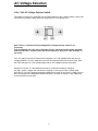
JC 3 Phono Preamplifier OWNER’S GUIDE Important Safety Instructions The lightning flash with the arrowhead symbol within an equilateral triangle is intended to alert the user to the presence of “dangerous voltage” inside the product that may constitute a risk of electric shock. The exclamation point within an equilateral triangle is intended to alert the user to the presence of important operating and maintenance instructions in the literature accompanying the product. TO REDUCE THE RISK OF ELECTRIC SHOCK, DO NOT REMOVE COVER. NO USER-SERVICEABLE PARTS INSIDE. REFER SERVICING TO QUALIFIED SERVICE PERSONNEL 1. Read Instructions — Read all the safety and operating instructions before operating this product. 2. Retain Instructions — Retain safety and operating instructions for future reference. 3. Heed Warnings — Adhere to all warnings on the product and in the operating instructions. 4. Follow Instructions — Follow all operating and use instructions. 5. Cleaning — Unplug this product from the wall outlet before cleaning. Use a damp cloth for cleaning. Clean the outside of the product only. 6. Attachments — Do not use attachments that are not recommended by the product manufacturer; they may be hazardous. 7. Water and Moisture — Do not use this product near water. 8. Accessories — Do not place this product on an unstable cart or stand. The product may fall, causing bodily injury and damage to the product. A product and cart combination should be moved with care. Quick stops, excessive force, and uneven surfaces may cause the product and cart to overturn. 9. Ventilation — Slots and openings in the cabinet are provided for ventilation to ensure reliable operation of the product and to protect it from overheating. These openings must not be blocked or covered. This product should not be placed in a built-in installation such as a bookcase or rack unless proper ventilation is provided. 10. Power Sources — Operate this product only from the type of power source indicated on the label. If you are not sure of the type of power supply to your home, consult your dealer or local power company. This product is equipped with a three-prong grounding plug. This plug will only fit into a grounding power outlet. If you are unable to insert the plug into the outlet, contact your electrician to replace your obsolete outlet. Do not defeat the safety purpose of the grounding plug. 11. Power Cord Protection — Power supply cords should be routed so that they are not likely to be walked on or pinched by items placed upon or against them. 12. Lightning — Unplug the unit from the wall outlet for added protection during a lightning storm and when it is left unattended and unused for long periods of time. This will prevent damage to the product due to lightning and power line surges. 13. Overloading — Do not overload wall outlets or extension cords. This can result in a fire or electric shock. 14. Inserting Objects into Unit — Never push objects of any kind into this product through any openings; they may touch dangerous voltage points or short out parts that could result in fire or electric shock. 15. Servicing — Do not attempt to repair or service this product yourself. Opening or removing covers may expose you to dangerous voltage and other hazards. Refer all servicing to qualified service personnel. 16. Damage Requiring Service — Unplug this product from the wall outlet and refer servicing to qualified service personnel under the following conditions: a) If the power-supply cord or plug is damaged. b) If liquid has been spilled into the product. c) If the product has been exposed to rain or water. d) If the product does not operate normally by following the operating instructions. e) If the product has been dropped or damaged in any way. f) If the product exhibits a distinct change in performance. 17. Replacement Parts — When replacement parts are required, be sure the service technician has used replacement parts specified by the manufacturer. Unauthorized substitutions may result in fire, electric shock, and other hazards. 19. Safety Check — Upon completion of any service or repairs to this product, ask the service technician to perform safety checks to determine that the product is in proper operating condition. 20. Wall or Ceiling Mounting — Mount the product to a wall or ceiling only as recommended. 21. Heat — The product should be situated away from heat sources such as radiators, heat registers, stoves, and other products (including amplifiers) that produce heat. 2 Table of Contents Introduction . . . . . . . . . . . . . . . . . . . . . . . . . . . . . . . . . . . . . . . . . . . . . . . . . Placement and Ventilation Guidelines . AC Voltage Selection . . . . . . . . . . . . . . . . . . . . . . . . . . . . . 5 . . . . . . . . . . . . . . . . . . . . . . . . . . . . . . . . . . . . . . . . . . 6 Audio Input and Output Connections . . . . . . . . . . . . . . . . . . . . . . . . . . . . . . 7 . . . . . . . . . . . . . . . . . . . . . . . . . . . . . . . . . 8 . . . . . . . . . . . . . . . . . . . . . . . . . . . . . . . . . . . . . . . . . . . 9 Other Connections on your JC 3 Rear Panel Controls Front Panel Operation . . . . . . . . . . . . . . . . . . . . . . . . . . . . . . . . . . . . . . . . . Frequently Asked Questions . . . . . . . . . . . . . . . . . . . . . . . . . . . . . . . . . . . . If You Require Assistance or Warranty Repair Specifications . 4 10 11 . . . . . . . . . . . . . . . . . . . . . . 12 . . . . . . . . . . . . . . . . . . . . . . . . . . . . . . . . . . . . . . . . . . . . . . 13 3 INTRODUCTION Thank You for Choosing Parasound Your new Parasound Halo JC 3 Phono Preamplifier is the pinnacle of analog audio technology and value engineering. It is legendary designer John Curl’s latest design, carrying on a proud tradition of phono preamp designs dating back to the 1970s. We are proud to offer you this exceptionally versatile audio component, knowing that it will bring you many years of enjoyment and dependability. We appreciate you taking the time to read these instructions and thank you for selecting Parasound. For updates and corrections to this manual, we invite you to check our web site, www.parasound.com Enjoy. The Parasound Staff Keeping Records for Future Reference Record the serial number located on the back panel or bottom of your JC 3 in the space below. Also note your Parasound Dealer’s name and telephone number. Your purchase receipt/bill of sale is required to determine if your JC 3 is eligible for Parasound warranty service. We recommend that you make an extra copy of your original purchase receipt/bill of sale and store it inside the JC 3’s carton. Parasound JC 3 Phono Preamplifier Serial #: __________________________________________________ Parasound Dealer: ________________________________________________________________ Parasound Dealer Phone Number: __________________________________________________________________ Date of Purchase: ________________________________________________________________ Important Warranty information There is no Parasound warranty for this unit if it was not purchased from an Authorized Parasound Dealer. Investigate warranty coverage statements made by an unauthorized dealer very carefully, as you will need to depend entirely upon your dealer, and NOT upon Parasound. Unauthorized dealers lack the capability to make repairs or arrange for repairs of Parasound equipment. A list of Authorized Parasound Dealers and detailed warranty information is available at www.parasound.com or you can call (415) - 397- 7100 between 8:30 am and 4 pm Pacific time. A missing or altered serial number could indicate that this unit was re-sold by an unauthorized dealer or is stolen merchandise. If this unit is missing its serial number or the serial number has been altered, you should return it to your dealer immediately for a full refund. 4 Unpacking Your JC 3 & Placement Guidelines Unpacking Your JC 3 Carefully remove your JC 3 from its shipping carton and locate all the enclosed accessories: • AC power cord • Two trigger wires, one with 3.5 mm mini plugs, one with a 2.5mm and a 3.5mm mini plug While you are unpacking your JC 3, inspect it thoroughly for possible shipping damage and tell your Parasound dealer immediately if you find any. If possible, save and store both the inner and outer cartons and–most especially–the foam packing inserts, to protect the JC 3 if you have to move it or ship it. You may wish to flatten the cardboard cartons to save room in storage after cutting the taped seams on the bottom flaps. This would be a good time to make a copy of your sales receipt to store with the JC 3’s original packing. Placement Guidelines The JC 3 will be easier to use and will last longer if you follow these simple guidelines: Place the JC 3 on a shelf that will adequately support its weight. Use input and output cables that are long enough to leave some slack; that will enable you to pull the JC 3 out of a cabinet to check or to change connections without inadvertently disconnecting cables. If you’re putting the JC 3 in a cabinet, it needs a space that’s at least 22 inches wide so you’ll be able to turn it around for access to its rear panel connections. Place your JC 3 where you can route input and output signal cables as far as possible from any AC cords. Where signal cables must cross AC cords they should do so only at a 90° right angle. Ventilation Requirements Always position the JC 3 horizontally. We recommend that you do not place the JC 3 above a power amplifier. • Do not install the JC 3 in an unventilated equipment cabinet or compartment. Pockets of stagnant hot air can build up even in a cabinet with an open front and back. A ventilation fan such as the Parasound Zbreeze is highly recommended to prevent “hot spots” in confined spaces. • • Rack Mounting Your Parasound JC 3 With its four feet removed, the JC 3’s front panel height occupies two rack spaces: 3.5" or 88.2 mm. (A single standard rack space occupies 1.75" vertical space.) For mounting in a standard 19” equipment rack, you must use the Parasound HRA 2 rack mount kit (purchased separately). The HRA 2 kit includes four bolts and eight plastic washers with raised “shoulders.” Slide one washer onto each mounting bolt with its raised shoulder pointing toward the panel hole. Carefully insert the bolt through the hole and slide the other washer on the bolt with its raised shoulder facing the rear side of the panel. The washers will sandwich the JC 3 panel and the four mounting bolts to prevent metal-to-metal contact between the JC 3 chassis, the equipment rack, and the other components mounted in the rack. Note: Tighten each bolt just enough to keep the unit secure in the rack to avoid deforming the shoulder washers. Eliminating metal-to-metal contact reduces the likelihood of creating a ground loop that might introduce hum into your system. 5 AC Voltage Selection 115v / 230v AC Voltage Selector Switch This switch is found on the underside of the chassis. Make sure the 115/230V switch is set for the correct AC line (mains) voltage before you plug in the JC 3’s AC power cord. Note: The JC 3 could be seriously damaged if AC Voltage Selector switch is set incorrectly. Prior to plugging your JC 3 into an AC power source, check the position of the 115v/230v switch on the JC 3’s chassis bottom and do not depend on the 115v or 230v markings on the carton. The 115V setting is correct for North America where the JC 3 can operate safely with AC line voltages between 110-120v. Most other countries will require the switch to be set to 230V. With the 230V setting the JC 3 can operate safely with AC line voltages between 220V-240V. Always turn off your JC 3 and disconnect its the AC cord before making or changing any input, output or trigger wire connections. Inserting or removing an input or output cable while the JC 3 and your preamp and power amplifiers are turned on can result in a blast of sound that can damage your loudspeakers. Make sure there is no strain or tension on any cables that could cause them to pull loose. 6 Connecting your JC 3 Always disconnect the AC cords to your JC 3 and power amplifier(s) before making or changing any input, output or trigger wire connections. Inserting or removing an input or output cable while the JC 3 or power amplifiers are turned on can result in a blast of sound that can damage your loudspeakers. Make sure there is no strain or tension on any cables that could cause them to pull loose. Audio Input Connections Connect your turntable’s signal cables to the Input jacks on the JC 3. It is a good idea to treat the turntable cable’s RCA plugs with Deoxit (http://www.deoxit.com/) to remove any oxidation on them. The turntable’s ground wire attaches to the JC 3 Ground terminal that is located between the two channel inputs and outputs. Important Note: Turntables and phono preamps are very sensitive to electromagnetic fields that can cause audible hum. To minimize hum follow these guidelines: • • • • • Place your turntable as far as possible from power amplifiers or power line conditioners. Run your turntable signal cables as far as possible from power amplifiers or power line conditioners. Do not run the turntable signal cables parallel with any AC cords. Wherever the turntable signal cord must cross AC wires they should cross at a 90o right angle. It might be necessary for you to experiment with the exact positioning of the turntable signal cables to minimize hum. 7 Audio Output Connections The JC 3 Output Jacks connect to the input jacks on your line level preamplifier. Each JC 3 module has two Output jacks, one Balanced XLR jack and one Unbalanced RCA jack. The balanced and unbalanced jacks are active simultaneously. If your preamplifier is equipped with balanced inputs we recommend using the JC 3 Balanced XLR output jacks for best possible signal-to-noise ratio and best rejection of external noise sources. Note: The JC 3 uses a fully differential balanced output circuit and does not employ phase inverters. The JC 3 does not invert polarity. Each channel module has a 3 position input load switch. Select the setting that matches your turntable cartridge type. If you are unsure which setting is best for your equipment you might want to contact the cartridge manufacturer. You may also try all three settings and use the setting which sounds the best. The MM setting is for moving magnet cartridges. It provides a 47k ohm load and appropriate gain for all MM cartridges. The MC 100 Ω setting is for most moving coil cartridges. It provides the higher gain required for low output or high output MC cartridges with a 100 ohm load that is ideal for nearly all MC cartridges. The MC 47k Ω setting provides the appropriate gain for MC cartridges with an alternative 47k ohm load. You can try both the 100 Ω or 47k Ω settings to see which sounds best in your system. The MC 47k Ω setting is also the recommended load for MI (moving iron) cartridges, such as Grados. Other Connections 12V In Jack The JC 3 12V input uses a mono 3.5mm sub-mini jack. To automatically trigger the JC 3 on and off, insert the trigger wire plug into this jack and plug the other end into your preamplifier’s 12V trigger output jack. When the JC 3 Turn On Options switch is set to 12V the JC 3 will turn On and Off with your preamplifier. If the preamplifier’s trigger output is a + and - terminal, you can cut the 3.5mm plug off one end of the included trigger wire and strip off about ¼” (6mm) of insulation. Attach the bare wires to the + and - terminals. The conductor with the white stripe on its insulation corresponds to the plug’s tip (+) and the conductor with the unmarked lead corresponds to the plug’s “sleeve” (-). Note: The Model JC 3 trigger circuit draws a negligible 15 mA from the preamplifier. 12V Loop Out Jack The Trigger Out jack lets you loop or “daisy-chain” the incoming trigger voltage to another component. AC Power Cord The IEC standard AC cord supplied with your JC 3 is an audiophile-grade component. Please connect it directly to an AC wall outlet or power conditioner that is always “live.” If possible, plug your JC 3 into the same AC outlet that your preamplifier is plugged into. If different AC outlets are used for the JC 3 and the preamplifier the ground potential may be higher or lower between the outlets, resulting in audible hum. 8 Rear Panel Controls Turn On Options Switch For your convenience, there are two ways the JC 3 can be turned on and off. Manual: Use the front panel On-Off button Auto: When the Turn On Options switch is set to the auto position, the JC 3 is turned on and off with an external +9 V to + 12 V voltage from your preamplifier. When the external voltage ceases the JC 3 will turn off immediately. When the Auto Turn On switch is set to Auto the front panel Power button is disabled. Input Load/Gain Switches Each Left and Right channel module has a 3 position load/gain switch. Select the setting that matches your turntable cartridge type. If you are unsure which setting is best for your equipment you might want to contact the cartridge manufacturer. You may also try all three settings and use the setting which sounds the best. . The MM setting is for moving magnet cartridges. It provides a 47k ohm load and the appropriate gain for all MM cartridges. The MC 100 Ω setting is for most moving coil cartridges. It provides the higher gain required for even very low output MC cartridges with a 100 ohm load that is ideal for nearly all MC cartridges. The MC 47k Ω setting provides the appropriate gain for MC cartridges with an alternative 47k ohm load. You can try both the 100 Ω and 47k Ω settings to see which sounds best in your system. The MC 47k Ω setting is also the recommended load for MI (moving iron) cartridges, such as Grados. Note: The JC 3 load options are restricted by intent. Designer John Curl believes that the most satisfactory playback of LP records depends on the elimination of compromises; complex input loading options are counter to this philosophy. AC Polarity Switch The JC 3 Polarity switch inverts the “hot” and “neutral” conductors of the incoming AC power. It does not affect the 3rd pin ground connection. In most cases the AC Polarity switch should remain in its Normal position. Occasionally, the only way to reduce or eliminate hum when listening with a phono preamp is to invert, or reverse the phase, of the phono preamp’s hot and neutral conductors. Note: Please turn off the JC 3 and unplug its AC cord before changing the setting of the AC Polarity switch. AC Power Switch This switch is provided to turn the JC 3 completely off when it will not be used for an extended time. Normally, this switch is left in the “on” position (upper section is pressed in). 9 Front Panel Controls On-Off Button Push once to turn on the JC 3. There will be a slight delay as the circuits stabilize and the DC servos settle down. When the JC 3 is turned on the blue glow around the On-Off button will be brighter and the red P badge will glow brighter. Push again to turn off the JC 3. Mono Button Press the Mono button one time to parallel the stereo channels to mono. Press a second time to return to stereo. Older mono records and stereo records with high levels of rumble will sound cleaner when you select mono on the JC 3. The Mono button will glow blue when stereo is selected and amber when mono is selected. Design Overview John Curl’s phono preamps are legendary. His approach to amplifying extremely low level signals gives the listener the best chance to experience the full emotional content of the source. In the JC 3 the physical implementation of the circuits closely follows the actual circuit topology and the layout is as compact as possible to minimize pickup of external noise. The preservation of low level signals is achieved by separating the critical audio signals from the non-audio circuits and non-audio wiring. Each channel has its own circuit board and each channel is fully enclosed in its own extruded aluminum “vault.” This vault shields the sensitive circuits from the JC 3’s power supply and from external sources of noise. The power transformer is an R-core type, which shares the advantages of a toroid transformer for minimizing radiated hum. However, it is far superior to a toroid transformer in preventing noise carried on the AC power line from passing through to its secondary windings and into the power supply. A second level of shielding separates the phono vaults from the power supply, power transformer and even the transformer wires running to the AC inlet on the rear panel. This shielding consists of two partitions of 3/8” low carbon “mild” steel to prevent any electromagnetic radiation from reaching the phono modules. The rear panel of the JC 3 is made of aluminum to prevent any electromagnetic interaction with the sensitive phono circuitry. Finally, the JC 3 has an on-board AC line conditioner to filter out high frequency noise and distortion that may be present on your AC power line. This eliminates a potential source of noise before it ever reaches the JC 3 power transformer. The resulting extremely low noise levels enable musical nuances to emerge from an utterly silent background. 10 Frequently Asked Questions Why won’t the JC 3 turn on when I press the On-Off button? - Check the setting of the Turn On Options switch. It must be set to Manual for the front panel On-Off button to function. Why won’t the JC 3 turn on with an external DC trigger? - Check the setting of the Turn On Options switch. It must be set to Auto for the 12V trigger to function. Why is there no sound from the speakers? - Check that AC is live and the “P” badge and both the On-Off button and Mono button are illuminated. - Check that input and output cables are secure at both ends. I can hear a background hum from the speakers - Ensure that you have attached your turntable’s ground wire to the ground terminal on the back panel of the JC 3 - Try changing the postion of the Polarity Invert switch on the back of the back panel of the JC 3 - Move audio cables and AC cords away from each other (while power is off). - Try to route audio cables and AC cords perpendicular to each other (while power is off). - Make sure insulating shoulder washers are used if unit is rack mounted. - Ensure that the power amps and the JC 3 are plugged into the same AC outlet The sound is distorted and too loud Are you using an MM cartridge and the JC 3 input load switches are set to MC? Change the settings to MM. The sound is weak Are you using an MC cartridge and the JC 3 input load switches are set to MM? Change the settings to MC 100 Ω or MC 47k Ω. When should I use the AC Polarity Invert switch? If you hear hum and you cannot eliminate it by moving your cables around. Should I use Balanced or Unbalanced connections? We generally recommend balanced connections if your preamplifier has balanced inputs. Recording and broadcast studios use balanced connections almost exclusively because of balanced lines’ inherent ability to reject noise and hum, even when components are far apart and connected by long cables. Many high-quality preamplifiers include balanced input connections with XLR jacks for the same reasons. The JC 3’s balanced outputs enable you to take full advantage of the inherent noise-rejection capability and superior sound quality of its precision circuits. Many serious listeners prefer the sonic characteristics of balanced connections because their lower inherent noise floor contributes to a more defined and spacious soundstage. 11 Are You Having Difficulty? Repair or Service Call your Parasound dealer first. If the dealer can’t help you with your problem we encourage you to call Parasound’s Technical Service Department, toll-free at 1-866-770-8324, Monday Friday, 8am - 4pm Pacific Time. We can suggest other diagnostic tests you can easily perform. If we determine that your JC 3 should be returned to Parasound or an Authorized Parasound Warranty Center for inspection and possible servicing, we will provide the location of a warranty center near you or shipping instructions for the unit’s return to Parasound. Before You Return Any Unit to Parasound for Service Before you send your unit to Parasound, you will need to obtain a specific Return Authorization (RA) number and shipping instructions from Parasound’s Technical Department. The RA number must be clearly marked on the outer carton. Use the original factory packing materials and arrange adequate insurance to cover its value. You must include a copy of your purchase receipt, since this document establishes the validity of this unit’s warranty. Warranty repairs are only performed by Parasound or Parasound Authorized warranty centers when your purchase receipt is from a Parasound Authorized Dealer or Parasound Authorized Reseller. Shipments Will Be Refused by Parasound Under the Following Conditions: 1. Unit was sent without the Parasound-assigned RA number marked on the carton. 2. Unit was sent in an unsuitable shipping carton and is likely to have been damaged in transit. 3. Unit has inadequate packing materials and is likely to have been damaged in transit. 4. Unit was shipped collect for shipping charges. We do not accept collect shipments. 5. Unit was shipped via the US Postal Service. 6. Unit was sent to an address other than the address instructed by our Technical Department. Note: The Parasound Technical Department shipping address is not the same as Parasound’s office address. The Parasound office does not accept packages. Warranty Repair Please read your accompanying Parasound Limited Warranty carefully to understand the applicable rights and limitations. This section provides instructions for obtaining repairs, both for units covered under the Parasound Limited Warranty and for units or situations which are outside the Warranty. Unit is not eligible for repair under the terms of the Parasound warranty if: 1. Unit was not purchased from a Parasound Authorized Dealer. 2. You do not have the original bill of sale or sales receipt from a Parasound Authorized Dealer. 3. You are not the original owner. The Parasound warranty is not transferable. 4. Unit’s serial number was removed, modified, or defaced. 5. Unit shows evidence of abuse and/or misuse. 6. Unit was modified in any way. 7. A prior repair was attempted by an unauthorized repair station. 12 Specifications Frequency Response XLR Pin Identification 20 Hz - 20 kHz, +/- 0.2 dB 1 = Ground (Shield) 2 = Positive 3 = Negative (Return) THD Distortion: < 0.005% at 20 kHz AC Power Requirement S/N Ratio (MM) 115 or 230 VAC 50 - 60 Hz 12 watts > 86 dB, input shorted, IHF A-weighted > 80 dB, input shorted, unweighted Dimensions S/N Ratio (MC) Width: 17-1/4” (437mm) Depth: 13-3/4” (350mm) Height, with feet: 4-1/8” (105mm) Height, without feet: 3-1/2” (89mm) > 75 dB, input shorted, IHF A-weighted > 70 dB, input shorted, unweighted Crosstalk: 72 dB at 1 kHz Weight Phono Input Impedance Net: 18 lbs. (8.2 Kg) Shipping: 25 lbs. (11.4 Kg) MM setting: 47k Ω MC setting: 47k Ω or 100 Ω Rack Mount Accessory Output Impedance HRA 2 (may be purchased separately) Unbalanced: < 100 Ω Balanced: < 100 Ω per leg Input Sensitivity at 1 kHz MM: 4mV in for 1.0V output MC: 0.4mV for 1.0V output Total Gain MM: 47dB MC: 68dB Specifications and features subject to change or improvement without notice. Copyright Parasound Product Inc., 2010 Rev. 1.0 www.parasound.com 13 Parasound Products, Inc. 2250 McKinnon Ave, San Francisco, CA 94124 415-397-7100 / Fax 415-397-0144 www.parasound.com 14