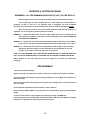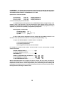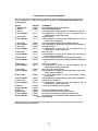
1
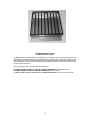
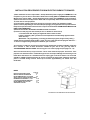
Operating Instructions
For All WW Electric Burnout Furnaces
With Computerized Programmable Controllers
W13, W14, W18
And WTNFII-10, -19
Furnaces Manufactured by
Paragon Industries, Inc.
2011 S. Town East Blvd.
Mesquite, Texas 75149
800-876-4328
972-288-7557
Fax 972-222-0646
[email protected]
www.paragonweb.com
1
OPERATING INSTRUCTIONS
FOR ALL WW ELECTRIC BURNOUT FURNACES WITH COMPUTERIZED
PROGRAMMABLE CONTROLLERS (W13, W14, W18) AND WW
COMPUTERIZED PROGRAMMERS (WTNFII-10, -19)
Computerized programming of burnout furnaces provides for simple push-button
operation for controlling your furnace during the burnout process. All programmers contain 3
built-in burnout programs which may be used immediately by pressing a couple of keys, or
you may create your own individualized custom program(s). Your programmable controller
allows up to four (4) custom programs. Program 1 allows for up to twenty (20) segments or as
we refer to "RAMPS". Programs 2, 3, and 4 allows for up to ten (10) segments. A segment or
"RAMP" consists of three (3) areas : 1) RATE OF HEATING/COOLING, 2) TEMPERATURE
SETTING (either °F or °C), and 3) HOLD TIME FOR THE TEMPERATURE. You may also enter a
DELAY to set the time you want the furnace to start the burnout program. All furnaces and
controllers are warranted for one year against defects in workmanship or material.
WW ELECTRIC BURNOUT FURNACES
All of our WW Electric Burnout Furnaces feature industrial quality construction and
sizes to fit every shop. They offer the simplest, most efficient and reliable means of burnout for
the lost wax caster. All of these furnaces are enclosed in trouble-free stainless steel cabinets.
Heating elements are secured in grooves inside the chamber; they are easily replaced when
necessary.
SPECIFICATIONS:
NO. W13
ELECTRICAL ........................................... 240V AC - 13A - 3000
WATTS
OUTSIDE DIMENSION ............................ 18"W X 21½"H X
21½"D
HEATING CHAMBER .............................. 13" X 13" X 9"
SHIPPING WEIGHT ................................. 135 LB.
NO. W14
ELECTRICAL ........................................... 240V AC - 16.7A - 4000
WATTS
OUTSIDE DIMENSION ............................ 19"W X 26½"H X 22"D
HEATING CHAMBER .............................. 14" X 14" X 14"
SHIPPING WEIGHT ................................. 165 LB.
NO. W18
ELECTRICAL ........................................... 240V AC - 24A - 5760 WATTS
OUTSIDE DIMENSION ............................ 24"W X 31"H X 27"D
HEATING CHAMBER .............................. 18" X 18" X 18"
SHIPPING WEIGHT ................................. 299 LB.
WW COMPUTERIZED PROGRAMMERS
SPECIFICATIONS:
NO. WTNFII-10 - COMPUTERIZED PROGRAMMER - 240V - 20A
NO. WTNFII-19 - COMPUTERIZED PROGRAMMER - 120V - 20A
2
FURNACE GRATES & TRAYS
For Wax Elimination Cycle
The WW Furnace Grate and Tray simplifies burnout procedure. It is no longer necessary to remove flasks and tray, then
replace flasks to avoid carbon build-up on heating elements, which is a primary cause of element failure. Now you merely
slide the stainless steel tray(s) from beneath the grate at the end of the wax elimination cycle and proceed with burnout. you
have removed 90% or more of the cause of offensive odor and air pollution. The grate is cast iron, like a cook-stove burner,
for strong support and long life.
Grates and trays are sized to fit standard electric burnout furnaces.
N0. WWT13 GRATE & TRAY FIT NOS. W13 & W14 FURNACES (12½" X 12½" X 1¼"H)
NO. WWT18 GRATE & TRAY FITS NO. W18 FURNACE (17" X 17" X 1½")
NO. WWT13 CAN BE USED IN ANY FURNACE WITH A CHAMBER MEASUREMENT OF 12½" X 12½" UP TO 14" X 14".
3
INSTALLATION PROCEDURES FOR WW ELECTRIC BURNOUT FURNACES
1) W13 and W14 Furnaces require 240V - 20 Amp dedicated power supply and a NEMA NO: 6-20
receptacle or you can wire in direct with a breaker box nearby (USE A LICENSED ELECTRICIAN).
W18 furnaces require 240V – 30 Amp dedicated power supply and a NEMA NO: 10-30 receptacle.
2) Set the furnace on a sturdy bench or table with a fire-proof top. Sides and back must be at least
12" from wall or side equipment.
3) The minimum voltage required to operate your furnace is 200V. The maximum is 250V.
4) Vent or Vents (depending on furnace model) and plug(s) are supplied for the top of the furnace.
Keep vents open at all times until all fumes or vapors are eliminated. STEAM WAX ELIMINATION IS
HIGHLY RECOMMENDED.
5) Read and remember the SAFETY RULES enclosed at all times.
6) Insert line cord plug into wall socket (or turn on breaker if direct wired).
a. The Controller will display all segments and the alarm sounds.
b. After a moment [ ldLE ] and the current temperature will alternately appear and the
alarm will stop.
(Remember - All programming, including permanent programs, begins from [ ldLE ] ).
7) Now refer to Permanent Program No. 1 (page 10). This is the wax burnout program which is 1 1½ hours in length and a good system check for your controller.
Your furnace is ready for use and you have two more permanent programs available. Programs
No. 2 and No. 3. One of these should be suitable for your use. If not, you may refer to
"PROGRAMMING INSTRUCTIONS" and set up your own custom program (see pages 14 - 16).
Vents are built into the top of your furnace. These vents must be kept open at all times. Their
purpose is to allow the fumes - created during burnout - to escape. Although not necessary, a vent
hood above the furnace is a desirable asset for helping get rid of these fumes. The vent hood
should be a DRAFT-TYPE vent hood, do not use a suction fan style hood, otherwise excessive
power is wasted during burnout. Place top of furnace approximately 12" below vent. See
illustration.
INDEX
Page No.
INSTALLATION INSTRUCTIONS
3-4
MISCELLANEOUS INFORMATION
5
PROGRAMMER DISPLAY & OPTIONS
6-8
SAFETY RULES, SPECIAL INSTRUCTIONS 9
PERMANENT PROGRAM NO. 1, 2,& 3
10-13
CUSTOM PROGRAM INFORMATION
14-15
PROGRAMMING STEP-BY-STEP
16
ADDITIONAL OPTIONS
17-18
A Vent Hood is recommended for burnout furnaces.
4
INSTALLATION FOR WW COMPUTERIZED PROGRAMMERS
WTNFII-10 & WTNFII-19
1) Be sure that your programmer is the same voltage as your burnout furnace:
WTNFII-10 - 240V
WTNFII-19 - 120V
Note - Do not plug in furnace or programmer at this time.
2) Mount programmer next to furnace. Holes are provided in the rear of the cabinet for hanging
your programmer on the wall with screws. A wall outlet of the proper voltage and amperage with a
dedicated line should be within 5 ft. (Do not use an extension cord). NOTE: THE WTNFII-19
COMPUTERIZED PROGRAMMER COMES WITH A NEMA 5-20R PLUG ON THE POWER CORD. IF
YOUR FURNACE IS RATED AT MORE THAN 20 AMPS, YOU CANNOT USE THIS PROGRAMMER. IF
YOUR FURNACE DRAWS LESS THAN 20 AMPS, YOU MAY INSTALL A STANDARD PLUG AT THE
AMPERAGE OF YOUR FURNACE. A LICENSED ELECTRICIAN SHOULD BE USED FOR ALL
ELECTRICAL WORK.
3) Insert the thermocouple into the hole at the back of the furnace. If no hole has been provided,
one must be drilled. CAUTION: DO NOT DRILL INTO HEATING ELEMENT. BE SURE THAT NO
METAL IS IN CONTACT WITH THERMOCOUPLE METAL PARTS.
4) Insert furnace line cord into socket on side of programmer. (NOTE: 120V and 240V PLUGS
COME IN MANY STYLES - IF YOUR PLUG DOES NOT MATCH THE SOCKET, IT MUST BE
REPLACED WITH ONE THAT DOES FIT) Your Computerized Programmer is rated for a maximum
of 20 Amps.
5) Insert programmer line cord into wall outlet. Again, if plug does not match outlet, outlet must be
replaced or unit can be wired direct. If wired direct, it must be done by a licensed and qualified
electrician. NOTE: WHEN POWER IS FIRST APPLIED, THE PROGRAMMER ALARM WILL GO OFF
FOR APPROXIMATELY TWO SECONDS..
6) The display will alternately read [ ldLE ] and the current temperature in the furnace.
7) If the display does not read [ ldLE ], press “STOP” then press “ENTER”.
8) Turn the furnace control to HIGH and your installation is complete. Now you can start using the
programmer.
9) To activate a program, refer to the operating instructions of our burnout furnaces.
NOTE: EVEN THOUGH THE PROGRAMMER IS OFF AT THIS TIME, THE UNIT WILL DISPLAY
THE AMBIENT TEMPERATURE INSIDE THE FURNACE.
5
PLACING FLASKS IN YOUR WW ELECTRIC BURNOUT FURNACE
IMPORTANT NOTE: YOU MUST USE EITHER STEAM WAX ELIMINATION OR THE WAX
ELIMINATION PROGRAM OF THE FURNACE. REMOVE THE WAX TRAY AFTER THE WAX
ELIMINATION CYCLE HAS COMPLETED. FAILURE TO REMOVE THE WAX TRAY WILL CAUSE
CARBON BUILD-UP ON THE EXPOSED ELEMENTS RESULTING IN PREMATURE ELEMENT
FAILURE. THE ELEMENTS ARE NOT WARRANTED.
When starting to load your furnace for wax elimination, be sure to use a tray to catch
the melted wax. We highly recommend our WWT13 or WWT18 Furnace Grate & Tray for this
purpose. Place flasks sprue hole down. Do not allow flasks to touch the sides, back or door of
the furnace, nor to touch each other's sides. Above all, do not allow a flask to touch the
thermocouple sensor located in upper center of back wall.
When stacking flasks, be sure that the sprue hole is exposed at all times, so that no
wax residue can be trapped. See illustration below. Flasks may touch edges (not sides) of each
other as shown as long as the sprue holes are exposed.
After the wax elimination cycle is complete, the flasks must be removed so that the wax
tray can be removed, then the flasks can be returned to the furnace, sprue hole up and again,
fully exposed and the firing procedure begun. NOTE: IF THE WWT13 OR WWT18 GRATE &
TRAY IS USED, IT IS NOT NECESSARY TO TURN SPRUE HOLE UP AFTER WAX ELIMINATION.
NOTE: THESE EXAMPLES SHOW CAPACITIES FOR OUR W18 FURNACE. THE SAME PRINCIPLES
APPLY FOR ANY BURNOUT FURNACE.
Stacking suggestions in 18x18x18 furnace for maximum capacity using different size flasks.
NOTE THAT SPRUE HOLE MUST BE EXPOSED BOTH DURING WAX ELIMINATION (SPRUE HOLE IS DOWN) OR WHEN
FIRING (SPRUE HOLE IS UP).
6
PROGRAMMER DISPLAY
The WW Computerized Programmer Display prompts the operator with various readings. The display
may appear peculiar due to the construction of each character in the standard LED display. Reading
that appear on the display and their descriptions are as follows.
DISPLAY
AbRT
DESCRIPTION
Abort The firing was stopped.
ALAR
Alarm ALAR appears either when you are entering an alarm temperature or when
the alarm is sounding during a firing. To stop an alarm, press any key except STOP. If the alarm
goes off when you first begin firing, it is because it was set for a lower temperature; than the present
temperature.
bAdP
Bad Program This message appears when a Ramp-Hold firing has been
programmed with 0 rate in the first segment.
CFG
Configuration This is an option that shows the factory configuration code for your
Sentry. This is for technicians who call the factory for support.
CHG-
Change °F/°C Choose between operation in degrees F of degrees C.
7
CPLT
DELA
minutes.
Complete
Delay
This means the firing completed as programmed.
DELA is a timer that starts the kiln later. Delay time appears in hours and
˚F 1
Temperature This prompt which appears in Ramp-Hold programming, is asking for
a target temperature. The number is to remind you which segment will use this target temperature.
ELEC
Electronics
The Sentry circuit board is rated for operation at temperatures up to
158˚F/70˚C. When the circuit gets hotter, the Sentry shuts off. The ELEC option tells you how hot the
circuit board is.
ETH
Electronics Too Hot
The Sentry circuit board is too hot, so the kiln was shut off.
FAIL
Failed The thermocouple failed. This can be due to a broken thermocouple, loose
thermocouple connection on the back of the Sentry, disconnected thermocouple wire, or a defective
controller.
FTH
Failed to Heat
The kiln cannot heat as fast as you programmed or is not heating at
all.
FTL
Firing Too Long The temperature rise is less that 27ْF/15ْC per hour and the firing
time is four hours longer than the current segment was programmed.
FULL
Full Speed
The rate, or temperature change per hour, is maximum.
Hd 1
Temperature Hold
When this message appears during Ramp-Hold
programming, it is asking you if you want to hold, or maintain, the target temperature of that segment.
If so, enter the length of hold time in hours and minutes (i.e. 1 hour 20 minutes = 01.20). The number
after Hd is the segment number. Each segment in a Ramp-Hold firing is numbered starting with 1.
HOLd
Temperature Hold
When this message appears during programming, it is asking
if you want to hold, or maintain, the target temperature. If so, enter the length of hold time in hours
and minutes (i.e. 1 hour 20 minutes = 01.20). When HOLd appears in the program review, it is
showing how much hold time has been entered.
HtdE
High Temperature Deviation
setting in the TEDE option.
ID
Computer ID
The temperature is above the temperature deviation
The ID option is for connection the Sentry to a personal computer.
IdLE
Ready to Begin The Sentry must display the idle message before you can begin firing
or programming.
LOCK
Program Lock With this option activated, a stored program cannot be altered or
removed from memory.
LTdE
Low Temperature Deviation
This message appears when the kiln is below the
temperature deviation setting in the TEDE option.
8
PF 2
Power Failure The power failed. When power came back on, the temperature was
below 212°F/100°C. Press [Abort}, then [Enter} to clear the display and return to “IdLE”.
PF 3
Power Failure
PF
Power Failure
power came back on.
PLOG
The power failed near the end of a firing.
There was a power failure during firing. The kiln continued firing after
Diagnostic Test Failure
RA 1
Rate
RA 1, RA 2, RA 3, etc., appears in Ramp-Hold programming, Program
Review, and Present Status. When RA 1, 2, 3, etc. appear during programming, the controller is
asking you for firing rate for each segment. Rate means how fast the firing progresses in degrees of
temperature per hour. Every segment must have a firing rate. The number after RA is the segment
number. Each segment in a Ramp-Hold firing is numbered starting with 1. Program Review shows
firing rate after RA 1, 2, 3, etc. In Present Status, RA 1, 2, 3, etc. means the segment that the firing is
in at that moment.
RST
Reset The RST option erases thermocouple offsets, selects °F operation, erases
stored programs in Ramp-Hold, and selects Type-S thermocouple. Note that if you use Reset, and
your kiln is equipped with a Type K thermocouple, you must use the TC option to select Type K.
(Reset selects Type S as a safety precaution. If you had a Type S thermocouple and Reset selected
Type K, your kiln would overfire. On the other hand, if you have a Type K thermocouple, Type S
selected would underfire your kiln. The Type K thermocouple is standard on most kilns.)
SFTY
Safety This is the maximum temperature the Sentry is programmed for your kiln. It
can be altered only at the factory.
SKIP
Skip Segment If you press the Skip Segment key during a firing, SKIP will appear. If
you press the key again, the firing will skip to the next segment.
SOFT
Sentry.
Software Version
This option gives the version of software loaded into your
STRT
Firing Started. This appears when firing begins. Do not be concerned if it takes a
moment for the relays to turn on. The Sentry is processing data.
TC
Thermocouple Type
Choose between Types K, S or R thermocouple. It is
important to select the correct type or the controller will not read temperature accurately.
TCOS
Thermocouple Offset Calibrate the controller’s temperature. This compensates for
temperature drift, or aging, of a thermocouple.
TC2--
Thermocouple
Thermocouple missing or wire disconnected.
TEDE
Temperature Deviation
The Sentry includes error messages to warn you that
the kiln is not maintaining the programmed temperature. The sensitivity of the error messages is
based on a temperature entered in the TEDE option.
USER
User Program In Ramp-Hold programming, the USER prompt is asking you where
you want to place the program in memory. The Sentry has four spaces in memory: 1, 2, 3, 4. Keep a
record, on paper, of the programs in memory.
9
SAFETY RULES
The warranty on your WW Electric Burnout Furnace and the WW Computerized Programmer
does not cover damage from overfiring, regardless of the circumstances. It is the operator's
responsibility to make sure that the furnace turns off at the end of the firing. Follow the safety
rules below in addition to the safety rules for your furnace.
UNPLUG THE FURNACE WHEN NOT IN USE.
DO NOT LEAVE THE FURNACE UNATTENDED NEAR END OF FIRING.
WEAR FIRING SAFETY GLASSES WHEN LOOKING INTO PEEPHOLE OF A HOT
FURNACE.
DO NOT TOUCH HOT SIDES OF FURNACE.
INSTALL YOUR FURNACE AT LEAST 12 INCHES FROM ANY WALL, EQUIPMENT OR
COMBUSTIBLE SURFACE.
DO NOT OPEN FURNACE DOOR UNTIL FURNACE HAS COOLED AND ALL SWITCHES
ARE OFF.
FIRE ONLY IN A WELL-VENTILATED, COVERED AND PROTECTED AREA AWAY FROM
FLAMMABLE MATERIALS. KEEP CORDSET AWAY FROM HOT SIDES OF FURNACE.
" DANGEROUS VOLTAGE " ! - DO NOT TOUCH HEATING ELEMENTS WITH ANYTHING.
DISCONNECT FURNACE BEFORE SERVICING.
NOT FOR HOUSEHOLD USE.
KEEP UNSUPERVISED CHILDREN AWAY.
TIME AND TEMPERATURE DISPLAY
During time display, a center display period appears. During temperature display, the period
disappears. The center display period separates hours from minutes (EXAMPLE - 1 hour and 30
minutes displays 01.30). NOTE THIS PECULIARITY: You can enter up to 99 hours and 99 minutes,
displayed as 99.99. In this example, .99 would seem to be tenths and hundredths of hours, yet .99
is 99 minutes.
HOW TO SELECT °F OR °C
If the controller is in °C mode, a lighted dot appears in the lower right side of the display. No dot
will appear if the unit is in the °F mode. To change from °F to °C, turn controller on, press ENTER (
* ) until the display shows [ IdLE ]. Then press (°°F/°°C) "0" button repeatedly until [ CHG ]
appears on the display. Press ENTER ( * ) and [°°F ] appears in the display. Press the #1 button to
change to [°°C]. Press Enter to save the change. To change from °C to °F, repeat the above
procedure.
10
PERMANENT PROGRAM NO. 1 [ - EL - ]
( USED FOR WAX ELIMINATION ONLY )
The wax elimination program will heat at the rate of 1250 °F (750 °C) per hour for 15
minutes or until the temperature reaches 300 °F (150 °C). NOTE: AS MUCH AS 15 °F (10 °C) OVERRUN MAY OCCUR. Then the program will hold 300 °F (150 °C) for one hour and turn itself off. You
may stop the program at any time by pressing the “STOP” (#) key.
A tray for trapping the wax must be used to protect the floor or hearth plate of the furnace.
The tray must be removed before the wax begins to burn or smoke. Once the wax is eliminated,
the furnace can be turned off; otherwise it will run for approximately 1¼ hours and then shut off
automatically.
During wax elimination, the sprue hole must be down. When the regular burnout cycle is
resumed, the flasks should be placed in the furnace with the sprue hole up.
ENTER PROGRAM NO. 1 [ - EL - ] AS FOLLOWS:
ACTION
1) Apply power
2) Press “1”
3) Press “ENTER”
4) Press “ENTER”
DISPLAY
[ ldLE ] alternating with current furnace temperature
[PROG] alternating with [EL]
[ ldLE ] alternating with current furnace temperature. Program saved.
[STRT] The furnace starts firing cycle.
WAX ELIMINATION
Most injection waxes will become liquid at 200 °F (93 °C) or less. However, some pattern
waxes and plastics melt as high as 350 °F (176 °C) and plastics burn-out at up to 500 °F (260 °C)
and produce odor and fumes. Obviously the plastic patterns must be handled differently than
injection wax. High heat and good ventilation. Regular injection waxes can be removed by using
PROGRAM NO. 1 WAX ELIMINATION PROGRAM or by using a Steam Wax Eliminator. Wax and
plastic burning produces carbon. Carbon build-up on the elements could cause a short that would
cause the elements to fail. To prevent this from happening leave the ventilation holes open and
occasionally run the Furnace up to it's maximum temperature of 1700 °F (925 °C). The carbon will
burn off the elements. We recommend our WWT13 & WWT18 Grate & Trays as an excellent way to
extend the life of the elements.
11
PERMANENT PROGRAM NO. 2 [ 5Hr]
This program operates the furnace for 1 hour at 300 °F (150 °C) and then advances slowly
to 1350 °F (730 °C) over a period of approximately 2 hours, then holds that temperature for 1 hour.
The programmer then lowers the temperature to 900 °F (480 °C) in a period of 1 hour and holds
that temperature for 3 hours. NOTE: AT THE END OF THE 5 HOUR PROGRAM, WE HAVE BUILT IN
3 EXTRA HOURS OF HOLD TIME IN CASE THE OPERATOR IS NOT READY TO CAST
IMMEDIATELY.
Once casting is completed, press “STOP” ( # ). Otherwise, the furnace will continue to
operate at 900 °F until 8 hours has passed and then shut off automatically. The display will show [
CPLt ].
FLASK TEMPERATURE FOR CASTING
We have used 900 °F (480 °C) as casting temperature for the flask. This temperature is
suitable for most castings, however many casters prefer other temperatures. This setting is
governed by experience. You may use any casting temperature you wish by entering your own
custom program.
ENTER PROGRAM NO. 2 [ 5 Hr ] AS FOLLOWS:
ACTION
1) Apply Power
2) Press “1”
3) Press “2”
4) Press “ENTER”
5) Press “ENTER”
DISPLAY
[ ldLE ] alternating with current furnace temperature
[PROG] alternating with [EL}
[5 HR]
[ ldLE ] alternating with current furnace temperature. Program saved.
[STRT] The furnace starts firing cycle.
12
PERMANENT PROGRAM NO. 3 [ 12 Hr ]
Before you use this program, you must first eliminate the wax with either steam or utilize
PROGRAM NO. 1. After the wax has been removed you may load the furnace SPRUE HOLE UP or
use our WWT13 or WWT18 Grate & Tray and the sprue holes can remain down. REMOVE WAX
TRAY AT END OF FIRST HOUR.
To start this program, see instructions below. The program begins with a slowly rising
temperature from ambient to 1350 °F (730 °C) which requires approximately 8½ hours. The
program then holds that temperature for 2 hours, and then reduces to a casting temperature of 900
°F (480 °C) and holds for 5 hours. Total time is 15 to 16 hours depending upon your load in the
furnace.
ENTER PROGRAM NO. 3 [ 12 Hr ] AS FOLLOWS:
ACTION
1) Apply Power
2) Press “1”
3) Press “3”
4) Press “ENTER”
5) Press “ENTER”
DISPLAY
[ ldLE ] alternating with current furnace temperature
[PROG] alternating with [EL}
[12 HR]
[ ldLE ] alternating with current furnace temperature. Program saved.
[STRT] The furnace starts firing cycle.
13
We feel that our 12 hour program ( No. 3 ), which is permanently programmed into your
controller, is the best and most useful program for the average casting operation. You can load
your furnace at 3 - 4 or 5:00 P.M. in the evening and arrive at 7 - 8 or 9:00 A.M. and cast. Many
casters prefer to load and cast in a 8 hour workday. We also have a 5 hour program (No. 2) that has
worked well for many years with flasks no larger than 4" to 5". Also, you have the option of
creating your own custom programs into the programmer (up to 6 different programs). This is
discussed on pages 11, 12 and 13.
Again, during the first hour of all programs the operator should be in attendance to remove
the melted wax from the wax tray which you should have on the floor of your furnace. This will do
two things. First, it will eliminate the odors and fumes created from the wax elimination, and
second, extend the life of the heating elements. The ventilation hole(s) at the top of the furnace
must remain open during this hour. After emptying wax from tray, replace the flasks with the sprue
hole up, or use our WWR13 or WWT18 Grate & Tray, then leave sprue hole down.
After burnout is complete, casting can be done. Once casting is complete, turn off furnace
by pressing STOP button. If you have not completed casting by the end of the final holding time,
the programmer will turn off.
PROGRAMMING A DELAY FIRING [ dELA ]
Regardless of the program that you run (either built-in or custom), you can insert a delay
period before the firing profile begins. This will allow you schedule the start of the program such
that you can cast upon your arrival. The only requirement is to have eliminated the wax either by
the furnace with PROGRAM NO. 1 or by Steam Wax Elimination.
Upon entering the desired program you are going to run (either permanent or custom) and
you reach the final step of displaying [ IdLE ], press DELAY START (3). The display will alternately
show
[ dELA ] and [ 00.00 ]. At this time you enter the amount of delay time you wish before the furnace
begins the burnout cycle (EXAMPLE: You program at 4:00 P.M. and you want a 5 hour burnout
(PROGRAM NO. 2) and you wish to cast at 8:00 A.M. - The delay entered is 11 hours [ 11.00 ] - This
starts the furnace at 3:00 A.M. and you are ready to cast at 8:00 A.M.). You can enter a delay start
time up to 99 hours.
After entering your delay start time press ENTER twice. After doing so, you can see the
timer in operation and counting down until the delay time entered has expired and the furnace
begins the selected burnout program.
14
ENTERING A CUSTOM PROGRAM
REMEMBER - ALL PROGRAMMING BEGINS WITH [ ldLE ] ON THE DISPLAY
Putting a program into your controller is the easiest way to understand its function.
Lets us begin with an 8 hour program. We use a slow steady rise in temperature to a
maximum of 1350 °F (730 °C) in all programs (this is suggested by most investment
manufacturers); then reduce the furnace temperature down to a casting temperature slowly.
Since we only have 8 hours, we will use smaller diameter flasks. We will program in 3
segments. You can program up to 20 segments if necessary.
SEGMENT 1 We will heat the furnace at a rate of 1250 °F (680 °C) per hour to a temperature of
300 °F (150 °C) and hold for 1 hour (this is our wax elimination cycle) - NOTE: OPERATOR
ATTENDANCE IS REQUIRED.
SEGMENT 2 We will then raise the furnace temperature to 1350 °F (730 °C) at a rate of 280 °F
(136 °C) per hour (requires approximately 4 hours) and then hold at 1350 °F for 2 hours.
SEGMENT 3 We will then lower the furnace temperature to 900 °F (480 °C) for our casting
temperature. We will program a 14 hour hold time for this temperature in case the
operator is not ready to cast at the end of the 8 hour period.
NOTE: YOU CAN PROGRAM ANY FLASK CASTING TEMPERATURE YOU WISH. WE FIND THAT
900 °F IS A GOOD TEMPERATURE FOR CASTING 14K YELLOW GOLD IN MOST INSTANCES.
DELAY START: You can also delay the start of the program if you wish (see instructions
following).
PROGRAMMING
1) Press keys slowly and firmly.
2) Before starting to program your controller, make sure all electrical connections are made.
3) At this time you must decide if you are going to program in °F or °C. Make sure controller is in
the correct mode.
4) You can program any schedule you wish as long as it is in 20 segments or less and not over 99
hours in length.
5) The maximum temperature of the controller is 1700 °F (925 °C).
6) You can add a DELAY TIME on any program from 1 minute(00.01) to 99 hours and 99 minutes
(99.99).
7) You can set the alarm on any program at any time by pressing 7 (ALARM) and
[ ALAr ] will appear on the display. Enter the new temperature and then press ENTER. [ ldLE ] will
display or your program will continue the burnout in progress.
15
8) REMEMBER - The furnace must be attended for the first hour so that the wax tray can be
removed (the use a of Steam Wax Eliminator will eliminate this). NOTE: FOR SAFETY REASONS AN OPERATOR SHOULD BE IN ATTENDANCE AT ALL TIME.
9) All times are entered as follows:
For 30 minutes
Press 30
For 1 hr. 15 min.
Press 115
For 2 hr. 45 min.
Press 245
* It is not necessary to put in the decimal.
Display shows 00.30
Display shows 01.15
Display shows 02.45
Your WW Computerized Programmer uses a RAMP/HOLD method of programming. It can
handle as many as 20 segments of time and temperature. Each segment raises or lowers the
temperature and holds it for the length of time you specify. Most burnout programs use only 3
segments, but you have the capability of programming 20 segments.
Each segment is controlled by:
A) HEATING RATE
B) TEMPERATURE
C) TIME
[ rA ]
[ °F ] or [ °C ]
[ HD ]
In other words, furnace temperature can be brought up from ambient to 300 °F in 15
minutes or over a period of several hours. This is governed by the RATE [ rA ].
To figure the HEATING RATE, 3 variables must be considered:
1) The ending temperature desired.
2) The starting temperature.
3) The length of time that this rate should take.
For example: If we want to heat a 300 °F furnace to 1350 °F over a 6 hour period, we would
calculate as follows:
ENDING TEMPERATURE (°°F).. ............ ............ 1350
STARTING TEMPERATURE (°°F) .......... ............ -300
DIFFERENCE (°°F) ........ ............ ............ ............ 1050
DIVIDE THE TEMPERATURE DIFFERENCE..... 1050 1050
BY THE NUMBER OF HOURS . ............ ............ ... 6
5
TO GET DEGREES PER HOUR ............ ............ ..... .175210
1050
3
350
We have illustrated above how to figure the rate for 5 hours and for 3 hours. Of course, to
decrease the temperature, we would simply subtract the ending temperature from the starting
temperature (in other words - reverse the procedure). Also, a decreasing rate is limited by how
long it takes for a heated mass to cool when the heating elements are turned off (in other words,
the larger the flask, the longer it takes to cool).
16
PROGRAMMING YOUR WW PROGRAMMER
You can enter your preferred burnout cycle at any time to suit your operation. You can even add four more
“Permanent Programs”. To make your own program remember “ALL PROGRAMMING BEGINS WITH [ ldLE }
ON THE DISPLAY”.
ACTION
1) Apply Power
2) Press 4
3) Press 1
4) Press ENTER
DISPLAY
[ ldLE ]
[ USEr ]
[ 1 ]
[ rA 1 ]
COMMENTS
All programming begins with [ ldLE ]
Path to the USEr program
This assigns your custom program a number (use 1 thru 4)
The programmer is asking for the 1st segment rate of
temperature increase or decrease
1250 °F per hour
The programmer is asking for the temperature you want to
reach in the 1st segment
This is the temperature for wax elimination (300 °F)
The programmer is asking how long you want to hold 300 °F
One hour at 300 °F
The programmer is asking for the 2nd segment rate of
temperature increase or decrease
280 °F per hour
The programmer is asking for the temperature you want to
reach in the 2nd segment
This is the temperature for the second burnout (1350 °F)
The programmer is asking for how long you want to hold 1350
°F
Two hours at 1350 °F
The programmer is asking for the 3rd segment rate of
temperature increase or decrease
450 °F per hour (cooling down)
The programmer is asking for what temperature you want to
reach in the 3rd segment
This is the temperature for the final burnout (casting
temperature)
The programmer is asking how long you want to hold 900 °F
Fourteen hours at 900 °F
The programmer is asking for the 4th segment rate of
temperature increase or decrease
0 °F per hour indicates end of program
5) Press 1250
6) Press ENTER
[ 1250 ]
[ °F 1 ]
7) Press 300
8) Press ENTER
9) Press 100
10) Press ENTER
[ 0300 ]
[ Hd 1 ]
[ 01.00 ]
[ rA 2 ]
11) Press 280
12) Press ENTER
[ 0280 ]
[ °F 2 ]
13) Press 1350
14) Press ENTER
[ 1350 ]
[ Hd 2 ]
15) Press 200
16) Press ENTER
[ 02.00 ]
[ rA 3 ]
17) Press 450
18) Press ENTER
[ 0450 ]
[ °F 3 ]
19) Press 900
[ 0900 ]
20) Press ENTER
21) Press 1400
22) Press ENTER
[ Hd 3 ]
[ 14.00 ]
[ rA 4 ]
23) Press 0
24) Press ENTER
25) Press 7
26) Press 9999
27) Press ENTER
28) Press ENTER
[ 0000 ]
[ ldLE ]
[ ALAr ]
This is the alarm temperature request
[ 9999 ]
This sets the alarm out of range (turns it off)
[ ldLE ]
If you wish you may enter a delay start at this time
[ STRT ]
If no delay time, then the temperature inside the furnace.
You are now cooking!
NOTE: Should you have any difficulty entering a custom program, call us and give us the rates and times. We
will supply step by step instructions.
17
HOLD (SOAK) TIME
“HOLD” or “SOAK” time means heat-soaking the flasks at the end of each segment. You can hold the
temperature in each segment up to 99 hours and 99 minutes.
PRESENT STATUS
“PRESENT STATUS” shows where the furnace is during firing. This is specially useful for firing that have
heating-up and cooling-down segments. To use “PRESENT STATUS”, press 5 on the key board during a
firing. The current segment will display momentarily.
SKIP SEGMENT
“SKIP SEGMENT” works only during firing. To skip a segment, press 9 on the key board. [ SstP ] will display
(if you change your mind and do not want to skip the segment, do nothing and the firing will continue as it
was). If you still want to skip the segment after pressing 9, press ENTER and [ rA ] will appear along with the
segment number you just skipped to.
DELAY FIRE
The “DELAY FIRE” programs the furnace to start its firing run (burnout) at a later time. It zeroes out after
each completed firing. To use the “DELAY FIRE” again, you need to reset it each time you start. Enter the
“DELAY FIRE” after you have chosen your program and you reach [ IdLE ] on the display. Press 3 on your
key board. Enter the delay in hours and minutes (such as 3 hours and 45 minutes is 345 - your display will
show [ 03.45 ] ) and the press ENTER. The display will then alternately display [ dELA ] and the time
remaining for the delay.
WARNING: NEVER LEAVE YOUR FURNACE UNATTENDED NEAR THE END OF A FIRING. WE CANNOT
GUARANTEE YOUR FURNACE AGAINST OVERFIRING EVEN THOUGH THE CONTROLLER IS AUTOMATIC.
THE OPERATOR ASSUMES FULL RESPONSIBILITY FOR TURNING THE FURNACE OFF AT THE PROPER
TIME.
REPEAT FIRINGS & PROGRAM REVIEW
To repeat last firing, just press ENTER from [ ldLE ]. The furnace will begin firing, but first, use your
PROGRAM REVIEW to make sure you are using the correct program. To start PROGRAM REVIEW press 6 on
the key board. Values for the last program used will be displayed one after another. You can also use
PROGRAM REVIEW during firing simply by pressing 6 on the key board.
SETTING THE ALARM BEFORE FIRING BEGINS
The alarm beeps when a preset temperature is reached.
1) At any time, press 7 on the key board. [ AlAr ] will appear alternating with the last alarm temperature
entered.
2) Enter the new alarm temperature. Then press ENTER. [ ldLE ] will appear or the current running profile will
continue.
3) To turn alarm off enter 9999.
When the alarm sounds during firing, shut it off by pressing any key. If it sounds as soon as the furnace
begins firing it is due to the fact that the alarm was set to 0000.
18
SETTING THE ALARM DURING FIRING
After you shut off the alarm during firing, you can set it to go off again later at either a higher temperature or
a cool-down temperature.
1) While the furnace is firing, press 7 on the key board.
2) Enter the new temperature.
3) Press ENTER and the furnace will continue firing.
POWER FAILURES
After a brief power failure during firing, [ PF ] will display, alternating with the temperature. Even though it
displays [ PF ], the furnace will continue to fire normally. The display shows [ PF ] simply to notify you of a
brief power failure. Press any key except STOP and normal temperature display will return.
[ ErrP ] appears after an extended power failure. In addition, after an extended power failure the controller
will sound a steady alarm.
When [ ErrP ] appears on the display, press ENTER. The hours fired and furnace temperature reached at the
time of the power failure will be displayed. Then [ ldLE ] will display.
See the “TROUBLE-SHOOTING section of your instructions for causes.
STEAM WAX ELIMINATION
We highly recommend that STEAM WAX ELIMINATION be used prior to a burnout in your furnace. This will
remove 90% of all waxes that melt at 200 °F or less and eliminates several things. First, it eliminates carbon
build-up on the elements of your furnace, giving it a longer life. Second, it eliminates noxious fumes and
odors, especially from closed-in areas. There are 3 sizes of Steam Wax Eliminators available. Ask your dealer
for more information.
19