1
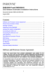
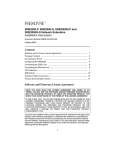
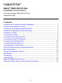
iMarc® 9550 DS3 Probe Installation Instructions Document Number 9550-A2-GN10-00 September 2005 Contents Software and Firmware License Agreement ................................................. 2 Product Documentation Online ..................................................................... 3 Unpacking and Inspecting the Equipment .................................................... 4 Installing the Brackets for Rack Mounting ..................................................... 4 Installing in a Rack ........................................................................................ 5 Connecting to Power ..................................................................................... 6 Connecting the Subscriber Port .................................................................... 8 Connecting to the DS3 Network ................................................................... 9 Connecting the Ethernet Port ....................................................................... 10 Connecting the Modem Port ......................................................................... 11 Connecting the Console Port ........................................................................ 12 Using the Asynchronous Terminal Interface ................................................. 13 Menu Hierarchy ............................................................................................. 14 Saving Configuration Options ....................................................................... 16 EMI Notices .................................................................................................. 17 CE Marking ................................................................................................... 17 Japan Notice ................................................................................................. 17 Important Safety Instructions ........................................................................ 18 Warranty, Sales, Service, and Training Information ...................................... 19 1 Software and Firmware License Agreement ONCE YOU HAVE READ THIS LICENSE AGREEMENT AND AGREE TO ITS TERMS, YOU MAY USE THE SOFTWARE AND/OR FIRMWARE INCORPORATED INTO THE PARADYNE PRODUCT. BY USING THE PARADYNE PRODUCT YOU SHOW YOUR ACCEPTANCE OF THE TERMS OF THIS LICENSE AGREEMENT. IN THE EVENT THAT YOU DO NOT AGREE WITH ANY OF THE TERMS OF THIS LICENSE AGREEMENT, PROMPTLY RETURN THE UNUSED PRODUCT IN ITS ORIGINAL PACKAGING AND YOUR SALES RECEIPT OR INVOICE TO THE LOCATION WHERE YOU OBTAINED THE PARADYNE PRODUCT OR THE LOCATION FROM WHICH IT WAS SHIPPED TO YOU, AS APPLICABLE, AND YOU WILL RECEIVE A REFUND OR CREDIT FOR THE PARADYNE PRODUCT PURCHASED BY YOU. The terms and conditions of this License Agreement (the “Agreement”) will apply to the software and/or firmware (individually or collectively the “Software”) incorporated into the Paradyne product (the “Product”) purchased by you and any derivatives obtained from the Software, including any copy of either. If you have executed a separate written agreement covering the Software supplied to you under this purchase, such separate written agreement shall govern. Paradyne Corporation (“Paradyne”) grants to you, and you (“Licensee”) agree to accept a personal, non-transferable, non-exclusive, right (without the right to sublicense) to use the Software, solely as it is intended and solely as incorporated in the Product purchased from Paradyne or its authorized distributor or reseller under the following terms and conditions: 1. Ownership: The Software is the sole property of Paradyne and/or its licensors. The Licensee acquires no title, right or interest in the Software other than the license granted under this Agreement. 2. Licensee shall not use the Software in any country other than the country in which the Product was rightfully purchased except upon prior written notice to Paradyne and an agreement in writing to additional terms. 3. The Licensee shall not reverse engineer, decompile or disassemble the Software in whole or in part. 4. The Licensee shall not copy the Software except for a single archival copy. 5. Except for the Product warranty contained in the manual, the Software is provided “AS IS” and in its present state and condition and Paradyne makes no other warranty whatsoever with respect to the Product purchased by you. THIS AGREEMENT EXPRESSLY EXCLUDES ALL OTHER WARRANTIES, WHETHER EXPRESS OR IMPLIED, OR ORAL OR WRITTEN, INCLUDING WITHOUT LIMITATION: a. Any warranty that the Software is error-free, will operate uninterrupted in your operating environment, or is compatible with any equipment or software configurations; and 2 b. ANY AND ALL IMPLIED WARRANTIES, INCLUDING WITHOUT LIMITATION IMPLIED WARRANTIES OF MERCHANTABILITY, FITNESS FOR A PARTICULAR PURPOSE AND NON-INFRINGEMENT. Some states or other jurisdictions do not allow the exclusion of implied warranties on limitations on how long an implied warranty lasts, so the above limitations may not apply to you. This warranty gives you specific legal rights, and you may also have other rights which vary from one state or jurisdiction to another. 6. IN NO EVENT WILL PARADYNE BE LIABLE TO LICENSEE FOR ANY CONSEQUENTIAL, INCIDENTAL, PUNITIVE OR SPECIAL DAMAGES, INCLUDING ANY LOST PROFITS OR LOST SAVINGS, LOSS OF BUSINESS INFORMATION OR BUSINESS INTERRUPTION OR OTHER PECUNIARY LOSS ARISING OUT OF THE USE OR INABILITY TO USE THE SOFTWARE, WHETHER BASED ON CONTRACT, TORT, WARRANTY OR OTHER LEGAL OR EQUITABLE GROUNDS, EVEN IF PARADYNE HAS BEEN ADVISED OF THE POSSIBILITY OF SUCH DAMAGES, OR FOR ANY CLAIM BY ANY THIRD PARTY. 7. The rights granted under this Agreement may not be assigned, sublicensed or otherwise transferred by the Licensee to any third party without the prior written consent of Paradyne. 8. This Agreement and the license granted under this Agreement shall be terminated in the event of breach by the Licensee of any provisions of this Agreement. 9. Upon such termination, the Licensee shall refrain from any further use of the Software and destroy the original and all copies of the Software in the possession of Licensee together with all documentation and related materials. 10. This Agreement shall be governed by the laws of the State of Florida, without regard to its provisions concerning conflicts of laws. Product Documentation Online Complete documentation for Paradyne products is available at www.paradyne.com. Select Support → Technical Manuals. Select: iMarc SLV Technical Description (9000-A2-GB30-10) – Describes the features, interfaces, and cables for iMarc SLV CSU/DSUs and routers. iMarc SLV Configuration Reference (9000-A2-GB31-30) – Lists and describes the configuration options available for iMarc SLV CSU/DSUs and routers. iMarc SLV SNMP Reference (9000-A2-GB32-20) – Describes support for MIBs, SNMP traps, and RMON in iMarc SLV CSU/DSUs and routers. iMarc SLV Operations Guide (9000-A2-GB33-30) – Explains how to operate and troubleshoot iMarc SLV CSU/DSUs and routers. To order a paper copy of a Paradyne document, or to speak with a sales representative, please call 1-727-530-2000. 3 Unpacking and Inspecting the Equipment ! HANDLING PRECAUTIONS FOR STATIC-SENSITIVE DEVICES This product is designed to protect sensitive components from damage due to electrostatic discharge (ESD) during normal operation. When performing installation procedures, however, take proper static control precautions to prevent damage to equipment. If you are not sure of the proper static control precautions, contact your nearest sales or service representative. The following components should be included in your package: 1 – iMarc® 9550 DS3 Probe 2 – Brackets for use in a 19-inch rack 2 – Brackets for use in a 23-inch rack 4 – Right-angle BNC adapters 2 – BNC Cables, 18 inches long 2 – BNC Cables, 30 inches long 2 – BNC Cables, 25 feet long If there is visible damage, do not attempt to connect the device. Contact your sales representative. Installing the Brackets for Rack Mounting The Probe can be installed in a rack using mounting brackets. Two brackets suitable for a 19-inch (48.3 cm) rack and two brackets suitable for a 23-inch (58.4 cm) Bay Networks or Nortel rack are shipped with the unit. Procedure To install the mounting brackets for rack mounting: 1. Locate the black screw nearest the front panel on each side of the unit. 2. Remove these two black screws (one from each side) before attempting to install the mounting brackets. 3. Identify six flat-head screws (for 19-inch racks) or six machine screws (for 23-inch racks) provided with the mounting brackets in the hardware kit. 4. Attach the brackets appropriate to your rack size. Tighten all screws firmly. 4 19-inch (483 mm) Rack Mount 23-inch (584 mm) EIA and Bay Networks Rack Mount 05-17709 23-inch (584 mm) Nortel Rack Mount Installing in a Rack Two types of mounting screws are provided. Use: #10-32 mounting screws for rails with threaded screw holes #12-24 mounting screws and self-retaining nuts for rails with unthreaded screw holes Procedure To install the Probe in a rack: 1. Determine where in the rack you will mount the Probe. If your rack does not have threaded screw holes, slip self-retaining nuts onto the rails where the Probe will be fastened. 2. Place the unit so that the brackets rest against the front of the rails. Insert screws in the bottom screw positions and hand-tighten them. 5 3. Insert and tighten the screws in the top screw positions, then tighten the bottom screws. Connecting to Power The Probe requires a 120 VAC, 60 Hz power source. Procedure To connect the 9550 DS3 Probe to power: ATMS TX ORK ATMC RD RX RIBER NETW TD OOF SUBSC LCV YEL AIS LOS 1. Connect a ground wire to the grounding screw on the front of the Probe. 9550 D S3 Ground 05-17707 2. Connect the other end of the wire to an earth ground. 6 3. Plug the socket end of the power cord into the power receptacle on the back of the Probe. 4. Plug the power cable into a 120 VAC, 60 Hz outlet. 05-17708 7 Connecting the Subscriber Port The Subscriber port connects to your DTE, such as a router. Procedure To connect the Subscriber port: 1. If clearance at the front of the Probe is limited, attach right-angle BNC adapters to the ends of two BNC cables. 2. Take the end of the receive cable and push it onto the SUBSCRIBER RX (Receive) connector. Turn the cable connector clockwise to lock it. 3. Take the end of the transmit cable and push it onto the SUBSCRIBER TX (Transmit) connector. Turn the cable connector clockwise to lock it. 4. Fix the cables to the rail with a cable tie or other strain relief device. 5. Connect the receive and transmit cables to the output and input connectors, respectively, of the DTE. DS3 Router IBER ORK OLE TX IBER ORK ATMC NETW ATMS RD YEL SUBSCR RX CONS TD M LOS MODE OOF ET LCV ETHERN OK Tx AIS NETW POWER Rx ALARM Tx TEST SUBSCR Rx 05-17702 6. If the DTE has a variable line build out (LBO) setting, ensure that it is matched to the cable length. 7. If the cable length is longer than 100 feet (30 meters), set the LBO on the T3 User Port Interface Options configuration screen to Long. The default is Short. See the iMarc SLV Configuration Reference. 8 Connecting to the DS3 Network The Network port connects to the packet network . Procedure To connect the Network port: 1. If clearance at the front of the Probe is limited, attach right-angle BNC adapters to the ends of two BNC cables. 2. Take the end of the receive cable and push it onto the NETWORK RX (Receive) connector. Turn the cable connector clockwise to lock it. 3. Take the end of the transmit cable and push it onto the NETWORK TX (Transmit) connector. Turn the cable connector clockwise to lock it. 4. Fix the cables to the rail with a cable tie or other strain relief device. 5. Connect the receive and transmit cables to the output and input connectors, respectively, of the DS3 source. DS3 Network Interface IBER ORK OLE TX IBER ORK ATMC NETW ATMS RD YEL SUBSCR RX CONS TD M LOS MODE OOF ET LCV ETHERN OK Tx AIS NETW POWER Rx ALARM Tx TEST SUBSCR Rx 05-17703 6. If the DS3 source device has a variable line build out (LBO) setting, ensure that it is matched to the cable length. 9 7. If the cable length is longer than 100 feet (30 meters), set the LBO on the T3 Network Interface Options configuration screen to Long. The default is Short. See the iMarc SLV Configuration Reference. Connecting the Ethernet Port The Ethernet port provides a 10/100BaseT connection that can be used for Telnet, FTP, and SNMP access to the Probe. Procedure To connect the Probe to an Ethernet hub, switch, or NIC: 1. Select the correct cable: — To connect the LAN port to a hub, use a standard Ethernet MDI cable — To connect the LAN port to a NIC, use an Ethernet MDIX (crossover) cable 2. Insert the 8-pin modular connector of the cable into the Ethernet jack on the Probe. It locks in place when it is fully seated. 3. Fix the cable to the rail with a cable tie or other strain relief device. 4. Connect the other end of the cable to your LAN or NIC. LAN IBER ORK OLE TX ATMC IBER ORK 05-17704 10 ATMS RD NETW RX SUBSCR TD CONS LOS M OOF MODE LCV ET OK ETHERN YEL Tx AIS NETW POWER Rx ALARM Tx TEST SUBSCR Rx Connecting the Modem Port The Probe supports asynchronous terminal interface sessions over its integral modem. Procedure To connect the Modem port: 1. Plug one end of an RJ11 telephone cable into the Modem port. 2. Plug the other end of the cable into an RJ11 telephone jack. IBER ORK OLE TX IBER ORK ATMC NETW 05-17705 RJ11 Telephone Jack 11 ATMS RD YEL SUBSCR RX CONS TD M LOS MODE OOF ET LCV ETHERN OK Tx AIS NETW POWER Rx ALARM Tx TEST SUBSCR Rx Connecting the Console Port The Console port can be used to connect a VT100-compatible terminal or a PC with terminal emulation software, providing direct access to the asynchronous terminal interface. Procedure To connect the Console port to a terminal or PC: 1. Press the 9-pin connector of a terminal cable onto the Console port socket. If the terminal will be permanently attached, fasten the connector and fix the cable to the rail with a cable tie or other strain relief device. 2. Connect the other end of the cable to your terminal or PC. IBER ORK OLE TX IBER ORK ATMC NETW ATMS RD YEL SUBSCR RX CONS TD M LOS MODE OOF ET LCV ETHERN OK Tx AIS NETW POWER Rx ALARM Tx TEST SUBSCR Rx 05-17706 3. Verify that the terminal or emulation software is set to: — 19200 bps — 8 data bits — No parity bit — 1 stop bit Any flow control type can be used. See Communication Port Options in the iMarc SLV Configuration Reference to change these settings. 12 Using the Asynchronous Terminal Interface The Probe should operate using the default (factory-set) configuration options, with exception to the changes specified in these installation instructions. Refer to the following table for help in navigating through the menus. Press the . . . To . . . Esc key Go back one screen or menu level. See Menu Hierarchy on page 14. Tab key, or Up (↑), Down (↓), Left (←), and Right (→) Arrow keys Move the cursor from one menu item to the next. Enter or Return key Complete the menu or option selection. Spacebar Display the next available setting when changing a configuration option. All the available settings for an option appears at the bottom of the screen. Follow these steps to go to the Configuration Edit/Display menu so you can start setting up the unit. Procedure To load a configuration for editing: 1. From the Main Menu, press the down arrow key twice so the cursor is on Configuration. 2. Press Enter to display the Configuration menu. The Load Configuration From menu appears. 3. Press Enter to select Current Configuration (the cursor is already on this selection). The Configuration Edit/Display menu appears. This sequence of steps would be shown as the menu selection sequence: Main Menu → Configuration 13 Menu Hierarchy The Menu Hierarchy shows the organization of the Probe’s asynchronous terminal interface screens. Status System and Test Status Self-Test Results Last System Reset Health and Status Test Status IP Path Connection Status Device Name IP Address Status Discovery Source PVC Connection Status Source and Destination ATM Link, VPI, VCI, Management Type, Status IP Routing Table Destination Mask Gateway Hop Type Interface TTL Performance Statistics Service Level Verification ATM VCC T3 User Line T3 Network Line Ethernet Clear All Statistics Trap Event Log Number of Trap Events Time of Day Event Display LEDs and Control Leads Test Identity System NAM Network Physical Tests Local Loopbacks Remote Loopbacks T3 User Port Physical Tests Local Loopbacks Remote Loopbacks IP Ping Lamp Test Abort All Tests 14 Configuration Control System Class of Service Definitions Monitored Protocol Definitions Service Level Verification General Network Physical ATM VPI, VCI Records T3 User Ports Physical ATM VPI, VCI Records PVC Connections Source and Destination Link, VPI, VCI, Management Type IP Subnet List Add and Display Local Subnets IP Path List Add and Display Static Paths Management and Communication Node IP Management PVCs General SNMP Management Telnet and FTP Session SNMP NMS Security SNMP Traps Ethernet Management Communication Port Modem Port System Information Device Name System Name, Location, Contact ATM Location ID Date Time Administer Logins Login ID Password Access Level Select Software Release Current Release Alternate Release Switch & Reset Telnet Disconnect Modem Reset Device 15 Saving Configuration Options Procedure To save a configuration option change: 1. Press Ctrl-a to switch to the function keys area at the bottom of the screen. 2. Type s or S (Save) and press Enter. The Save Configuration To menu appears. 3. Press Enter again to save your changes to the Current Configuration. 4. Press Esc until the Configuration Edit/Display menu reappears to continue configuring the unit. Press Ctrl-a, type m (MainMenu), and press Enter to return to the Main Menu. 16 EMI Notices United States – EMI Notice This equipment has been tested and found to comply with the limits for a Class A digital device, pursuant to Part 15 of the FCC rules. These limits are designed to provide reasonable protection against harmful interference when the equipment is operated in a commercial environment. This equipment generates, uses, and can radiate radio frequency energy and, if not installed and used in accordance with the instruction manual, may cause harmful interference to radio communications. Operation of this equipment in a residential area is likely to cause harmful interference in which case the user will be required to correct the interference at his own expense. The authority to operate this equipment is conditioned by the requirements that no modifications will be made to the equipment unless the changes or modifications are expressly approved by Paradyne Corporation. If the equipment includes a ferrite choke or chokes, they must be installed as described in the installation instructions. Canada – EMI Notice This Class A digital apparatus complies with Canadian ICES-003. Cet appareil numérique de la classe A est conforme à la norme NMB-003 du Canada. CE Marking When the product is marked with the CE mark on the equipment label, a supporting Declaration of Conformity may be downloaded from the Paradyne World Wide Web site at www.paradyne.com. Select Library → Technical Manuals → CE Declarations of Conformity. Japan Notice Class A ITE This is a Class A product based on the standard of the Voluntary Control Council for interference by Information Technology Equipment (VCCI). If this equipment is used in a domestic environment, radio disturbance may arise. When such trouble occurs, the user may be required to take corrective actions. 17 ! Important Safety Instructions 1. Read and follow all warning notices and instructions marked on the product or included in the manual. 2. Slots and openings in the cabinet are provided for ventilation. To ensure reliable operation of the product and to protect it from overheating, these slots and openings must not be blocked or covered. 3. Do not allow anything to rest on the power cord and do not locate the product where persons will walk on the power cord. 4. Do not attempt to service this product yourself, as opening or removing covers may expose you to hazardous voltage or to other risks. Refer all servicing to qualified service personnel. 5. General purpose cables are used with this product for connection to the network. Special cables, which may be required by the regulatory inspection authority for the installation site, are the responsibility of the customer. Use a UL Listed, CSA certified, minimum No. 26 AWG line cord for connection to the Digital Subscriber Line (DSL) network. 6. When installed, the product must comply with the applicable Safety Standards and regulatory requirements of the country in which it is installed. If necessary, consult with the appropriate regulatory agencies and inspection authorities to ensure compliance. 7. A rare phenomenon can create a voltage potential between the earth grounds of two or more buildings. If products installed in separate buildings are interconnected, the voltage potential may cause a hazardous condition. Consult a qualified electrical consultant to determine whether or not this phenomenon exists and, if necessary, implement corrective action prior to interconnecting the products. 8. Input power to this product must be provided by one of the following: (1) a UL Listed/CSA certified power source with a Class 2 or Limited Power Source (LPS) output for use in North America, or (2) a certified power source, with a Safety Extra Low Voltage (SELV) output having a maximum of 240 VA available, for use in the country of installation. 9. In addition, since the equipment is to be used with telecommunications circuits, take the following precautions: — Never install telephone wiring during a lightning storm. — Never install telephone jacks in wet locations unless the jack is specifically designed for wet locations. — Never touch uninsulated telephone wires or terminals unless the telephone line has been disconnected at the network interface. — Use caution when installing or modifying telephone lines. — Avoid using a telephone (other than a cordless type) during an electrical storm. There may be a remote risk of electric shock from lightning. — Do not use the telephone to report a gas leak in the vicinity of the leak. 18 Warranty, Sales, Service, and Training Information Contact your local sales representative, service representative, or distributor directly for any help needed. For additional information concerning warranty, sales, service, repair, installation, documentation, training, distributor locations, or Paradyne worldwide office locations, use one of the following methods: Internet: Visit the Paradyne World Wide Web site at www.paradyne.com. (Be sure to register your warranty at www.paradyne.com/warranty.) Telephone: Call our automated system to receive current information by fax or to speak with a company representative. — Within the U.S.A., call 1-800-795-8004 — Outside the U.S.A., call 1-727-530-2340 Copyright 2005 Paradyne Corporation. Printed in U.S.A. 19 *9550-A2-GN10-00* *9550-A2-GN10-00* 20