Transcript
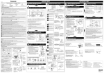
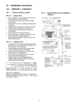
INDOOR UNIT F616355 Required tools for Installation Works 13 Multimeter 14 Torque wrench 13.3 Ibf.ft (18 N•m (1.8 kgf.m)) 31.0 Ibf.ft (42 N•m (4.3 kgf.m)) 40.6 Ibf.ft (55 N•m (5.6 kgf.m)) 47.9 Ibf.ft (65 N•m (6.6 kgf.m)) 73.8 Ibf.ft (100 N•m (10.2 kgf.m)) 15 Vacuum pump 16 Digital Micron Gauge SAFETY PRECAUTIONS • • • Read the following “SAFETY PRECAUTIONS” carefully before installation. Electrical work must be installed by a licensed electrician. Be sure to use the correct rating of the power plug and main circuit for the model to be installed. The caution items stated here must be followed because these important contents are related to safety. The meaning of each indication used is as below. Incorrect installation due to ignoring of the instruction will cause harm or damage, and the seriousness is classified by the following indications. WARNING 1 (Refer to “Select the best location” section) 2 INDOOR UNIT INSTALLATION Do not turn over the unit without it’s shock absorber during pulling out the piping. It may cause intake grille damage. HOW TO FIX INSTALLATION PLATE pull o ut th e pip i pull o ut t h Use shock absorber during pulling out the piping to protect the intake grille from damage. ep ipi ng 1 2 • ng Piping The mounting wall shall be strong and solid enough to prevent it from the vibration. This indication shows the possibility of causing death or serious injury. Piping 3 SELECT THE BEST LOCATION (Refer to “Select the best location” section) A Model PUSH More than 2 2 screw A D XE9PKUA, XE12PKUA B C Symbol with dark background denotes item that must be carried out. 5 1/16" 1. FOR THE RIGHT REAR PIPING (128 mm) DISTANCE TO PIPE HOLE CENTER 128 mm WARNING 17/32" Do not install outdoor unit near handrail of veranda. When installing air-conditioner unit on veranda of a high rise building, child may climb up to outdoor unit and cross over the handrail causing an accident. Do not use unspecified cord, modified cord, joint cord or extension cord for power supply cord. Do not share the single outlet with other electrical appliances. Poor contact, poor insulation or over current will cause electrical shock or fire. 9 (241.5 mm) Measuring Tape DISTANCE TO PIPE HOLE CENTER 128 mm 5 (128 mm) 1 19 9/32" (490 mm) XE9PKUA, XE12PKUA When installing or relocating air conditioner, do not let any substance other than the specified refrigerant, eg. air etc mix into refrigeration cycle (piping). Mixing of air etc will cause abnormal high pressure in refrigeration cycle and result in explosion, injury etc. Do not add or replace refrigerant other than specified type. It may cause product damage, burst and injury etc. For R410A model, use piping, flare nut and tools which is specified for R410A refrigerant. Using of existing (R22) piping, flare nut and tools may cause abnormally high pressure in the refrigerant cycle (piping), and possibly result in explosion and injury. Thickness or copper pipes used with R410A must be more than 1/32" (0.8 mm). Never use copper pipes thinner than 1/32" (0.8 mm). It is desirable that the amount of residual oil is less than 0.0008 oz/ft (40 mg/10 m). Engage authorized dealer or specialist for installation. If installation done by the user is incorrect, it will cause water leakage, electrical shock or fire. 2 3 7/32" (82 mm) 3 17 9/32" (439 mm) Use the attached accessories parts and specified parts for installation. Otherwise, it will cause the set to fall, water leakage, fire or electrical shock. Install at a strong and firm location which is able to withstand the set’s weight. If the strength is not enough or installation is not properly done, the set will drop and cause injury. For installation work, follow all electrical, building, plumbing, local codes, regulations and these installation instructions. If electrical circuit capacity is not enough or a defect is found in electrical work, it will cause electrical shock or fire. Do not use spliced wires for indoor / outdoor connection cable. Use the specified indoor / outdoor connection cable, refer to instruction 5 INDOOR/OUTDOOR UNIT ELECTRICAL WIRING and connect tightly for indoor/outdoor connection. Clamp the cable so that no external force will have impact on the terminal. If connection or fixing is not perfect, it will cause heat-up or fire at the connection. Wire routing must be properly arranged so that control board cover is fixed properly. If control board cover is not fixed perfectly, it will cause fire or electrical shock. This equipment must installed with an Earth Leakage Circuit Breaker (ELCB) or Ground Fault Current Interrupter (GFCI) or Appliance Leakage Current Interrupter (ALCI) that has been certified by an NRTL Certified Testing Agency and that is suitable for the voltages and amperages involved. Otherwise, if may cause electrical shock and fire in case of equipment breakdown. During installation, install the refrigerant piping properly before running the compressor. Operation of compressor without fixing refrigeration piping and valves at opened condition will cause suck-in of air, abnormal high pressure in refrigeration cycle and result in explosion, injury etc. During pump down operation, stop the compressor before removing the refrigeration piping. Removal of refrigeration piping while compressor is operating and valves are opened will cause suck-in of air, abnormal high pressure in refrigeration cycle and result in explosion, injury etc. Tighten the flare nut with torque wrench according to specified method. If the flare nut is over-tightened, after a long period, the flare may break and cause refrigerant gas leakage. The center of installation plate should be at more than 1 at right and left of the wall. The distance from installation plate edge to ceiling should more than 2. From installation plate left edge to unit’s left side is 3. From installation plate right edge to unit’s right is 4. b : For left side piping, piping connection for liquid should be about 5 from this line. : For left side piping, piping connection for gas should be about 6 from this line. Ventilate if there is refrigerant gas leakage during operation. It may cause toxic gas when the refrigerant comes into contact with fire. This equipment must be properly earthed. Earth line must not be connected to gas pipe, water pipe, earth of lightning rod and telephone. Otherwise, it may cause electrical shock in case of equipment breakdown or insulation breakdown. 3 TO DRILL A HOLE IN THE WALL AND INSTALL A SLEEVE OF PIPING 1. Insert the piping sleeve to the hole. 2. Fix the bushing to the sleeve. 3. Cut the sleeve until it extrudes about 19/32" (15 mm) from the wall. Wall 19/32" CAUTION 2 Approx. 7/32" - 9/32" (5-7 mm) 1 7 Battery 2 8 CZ-3F5, 7BP CZ-4F5, 7, 10BP CZ-52F5, 7, 10BP Installation parts you should purchase ( ) Installation plate 1 Model XE9PKUA 8700 XE12PKUA 11500 Piping size Gas Liquid 49.2 ft (15 m) 9.8 ft (3 m) 65.6 ft (20 m) 0.2 oz/ft (20 g/m) Conduit Cover Putty ( ) (Gum Type Sealer) 8 ft (2.4 m) or more (Left and right are identical) Bend the pipe as closely on the wall as possible, but be careful that it doesn’t break. Floor / Grade level Vinyl tape (wide) ( ) • Apply after carrying out a drainage test. • To carry out the drainage test, remove the air filters and pour water into the heat exchanger. Insulation of piping connections • Carry out insulation after checking for gas leaks and secure with vinyl tape. Vinyl tape Attaching the remote control holder to the wall Saddle ( ) Remote control holder fixing screws 6 1 2 24.6 ft (7.5 m) Example: For XE9PKUA If the unit is installed at 32.8 ft (10 m) distance, the quantity of additional refrigerant should be 1.64 oz (50 g) .... (32.8 - 24.6) ft x 0.2 oz/ft = 1.64 oz. ((10-7.5) m x 20 g/m = 50 g) • This illustration is for explanation purposes only. The indoor unit will actually face a different way. 1. Press the lower left and right side of the unit against the installation plate until hooks engage with their slot (sound click). Installation plate Unit’s hook To t a ke o u t t h e u n i t , push the marking at the bottom unit, and pull it slightly towards you to disengage the hooks from the unit. 3 (10 15/1 or 0 m 6" mo m) re Connection cable 23 A b (7 /4" ou 0- - 3 t 80 5 m /32" m ) Connection cable Gas side piping ( ) 1 (3 1 13 0 or 0 m /16" mo m re ) Additional drain hose ( ) ACCEPT Point down 1. To cut 2. To remove burrs Clamp handle Red arrow mark Conductor over inserted 3. To flare 1. Connect a charging hose with a push pin to the Low side of a charging set and the service port of the 3-way valve. 2. Connect the micron gauge between vacuum pump and service port of outdoor units. 3. Turn on the power switch of the vacuum pump and make sure that connect digital micron gauge and to pull down to a value of 500 microns. 4. To make sure micron gauge a value 500 microns and close the low side valve of the charging set and turn off the vacuum pump. 5. Disconnect the vacuum pump house from the service port of the 3-way valve. 6. Tighten the service port caps of the 3-way valve at a torque of 13.3 Ibf.ft (18 N•m) with a torque wrench. 7. Remove the valve caps of both of the 2-way valve and 3-way valve. Position both of the valves to “Open” using a hexagonal wrench (5/32" (4 mm)). 8. Mount valve caps onto the 2-way valve and the 3-way valve. • Be sure to check for gas leakage. Power Supply Single Phase 208/230V 60Hz min AWG14 Terminal Board • Earth wire longer than other AC wires for safety reasons - If micron gauge value does not descend 500 microns, take the following measures: If the leak stops when the piping connections are tightened further, continue working from step 3. If the leak does not stop when the connections are retightened, repair location of leak. Do not release refrigerant during piping work for installation and reinstallation. Be careful with the liquid refrigerant, it may cause frostbite. Holder Power supply cord Indoor & outdoor connection cable PIPING INSULATION 1. Please carry out insulation at pipe connection portion as mentioned in Indoor/Outdoor Unit Installation Diagram. Please wrap the insulated piping end to prevent water from going inside the piping. 2. If drain hose or connecting piping is in the room (where dew may form), please increase the insulation by using POLY-E FOAM with thickness 1/4" (6 mm) or above. Please follow the steps below to take out front grille if necessary such as when servicing. 1. Remove both left and right side decorative cover of the front grille as shown in the illustration at right, and then remove the 2 mounting screws. 2. Pull the lower section of the front grille towards you to remove the front grille. DISPOSAL OF OUTDOOR UNIT DRAIN WATER Front panel Front grille • Screw • If a drain elbow is used, the unit should be placed on a stand which is taller than 1 3/16" (30 mm) If the unit is used in an area where temperature falls below 32°F (0°C) for 2 or 3 days in succession, it is recommended not to use a drain elbow, for the drain water freezes and the fan will not rotate. How to pull the piping and drain hose out, in case of embedded piping. Apply putty or caulking material to seal the wall opening. PROHIBITED n tha re Mo 9 /32" m) 45 50 m (11 Connection cable PVC tube for drain hose (VP-20) • How to insert the connection cable and drain hose in the case of left piping. than More 0 mm) Drain hose 7 from main unit 1 /2" (4 18 PVC tube (VP-65) for piping and connection cable ° 45 PVC tube for drain hose (VP-30) Cable Drain hose Piping Cable Piping Indoor unit 2 27/32" (72 mm) (For right piping, follow the same procedure) Drain hose adapter 8 usage Improper flaring Inclined Surface Cracked Uneven damaged thickness When properly flared, the internal surface of the flare will evenly shine and be of even thickness. Since the flare part comes into contact with the connections, carefully check the flare finish. • Join indoor drain hose to 3/4" (20 mm) nominal PVC pipe size by using drain hose adapter 8 when necessary. CHECK THE DRAINAGE • Sleeve for piping hole Piping PROHIBITED Hose Drain elbow 7 Install the hose at an angle so that the water smoothly flows out. When reinstalling the front grille, first set the vertical airflow direction louver to the horizontal position and then carry out above steps 2 - 3 in the reverse order. AUTO SWITCH OPERATION Conductor not fully inserted 0 – 1/32" (0-0.5 mm) Copper pipe More than 45 9/32" (1150 mm) Holder 1. Please cut using pipe cutter and then remove the burrs. 2. Remove the burrs by using reamer. If burrs are not removed, gas leakage may be caused. Turn the piping end down to avoid the metal powder entering the pipe. 3. Please make flare after inserting the flare nut onto the copper pipes. Bar Drain hose Adjust the piping slightly downwards. CUTTING AND FLARING THE PIPING Handle Piping Connection cable Drain hose PVC tube for drain hose Liquid side piping ( ) " ) 3 /8 m 39 00 more 0 (1 or m Drain cap (5 mm) or more Yoke Core Close Earth wire longer than other AC wires for safety reasons Earth lead wire shall be Yellow/Green (Y/G) in colour and should be longer than other lead wires as shown in the figure for electrical safety in case of slipping. HOW TO TAKE OUT FRONT GRILLE (This can be used for left rear piping and bottom piping also.) Drain hose 7/32" Bar Three-way valve Drain hose Connection cable (gap between wires) Reamer • Outdoor unit Gas side Decorative Cover Indoor and outdoor connection cable Two-way valve Liquid side piping Guide surface • Please refer to “Insulation of piping connection” column as mentioned in indoor/outdoor unit installation. Gas side piping Rear view for left piping installation Conductor fully inserted Pipe WARNING 6 Insert the connection cable Step-8 Secure the Indoor Unit Earth wire longer than others AC wires for safety reason Liquid side Close Disconnect Switch Field supply Grounding wire 9. Secure the wire onto the control board with the holder (clamper). 10.After completing wiring connections, reattach the particular plate and control board cover (metal and resin) to the original position with the screws. 11.For wire stripping and connection requirement, refer to instruction 5 of indoor unit. Terminal Board Indoor/outdoor connecting terminal board Indoor unit 3 L1 L2 3 Wire stripping EVACUATION OF THE EQUIPMENT WHEN INSTALLING AN AIR CONDITIONER, BE SURE TO EVACUATE THE AIR INSIDE THE INDOOR UNIT AND PIPES in the following procedure. Drain hose Secure the Indoor Unit Torque wrench Vacuum pump This equipment must be properly earthed. Insulate and finish the Step-7 piping • No loose strand when inserted 208/230V min AWG16 Piping Indoor unit Spanner or Wrench 2 Sleeve for piping hole Cut and flare the embedded piping • Please refer to “Connecting the piping” column in outdoor unit section. (Below steps are done after connecting the outdoor piping and gas-leakage confirmation.) WIRE STRIPPING AND CONNECTING REQUIREMENT Connection cable ( ) It is advisable to avoid more than 2 blockage directions. For better ventilation & multiple-outdoor installation, please consult authorized dealer/specialist. Hook the indoor unit onto the upper portion of installation plate. (Engage the indoor unit with the upper edge of the installation plate). Ensure the hooks are properly seated on the installation plate by moving it in left and right. Rear Side of Indoor Unit Earth lead wire shall be Yellow/Green (Y/G) in colour and shall be longer than other lead wires as shown in the figure for electrical safety in case of slipping. 3 (1 15/ 0 or 0 m 16" mo m re ) Remote control 3 Remote control holder 5 Pull the connection cable into Indoor Unit Step-6 Connect the piping Chassis 3 4 Control Board Cover (Resin) 1 208/230V min AWG16 Grounding wire min AWG16 • When determining the dimensions of the piping, slide the unit all the way to the left on the installation plate. • Refer to the section “Cutting and flaring the piping”. Lock Nut Sleeve ( ) 1 31/32" (50 mm) or more Min. Max. Piping Std. Max. Additional Piping Piping Length for Length Elevation Refrigerant Length Length add. gas 3/8" (9.52 mm) 1/4" 24.6 ft (6.35 mm) (7.5 m) 1/2" (12.7 mm) 2 Bushing-Sleeve ( ) INDOOR UNIT Capacity (Btu/h) Conduit Connector WARNING • SELECT THE BEST LOCATION If an awning is built over the unit to prevent direct sunlight or rain, be careful that heat radiation from the condenser is not obstructed. There should not be any animal or plant which could be affected by hot air discharged. Keep the spaces indicated by arrows from wall, ceiling, fence or other obstacles. Do not place any obstacles which may cause a short circuit of the discharged air. If piping length is over the [piping length for additional gas], additional refrigerant should be added as shown in the table. Recommended installation height for outdoor unit should be above the seasonal snow level. Step-4 Putty or caulking compound This equipment must be properly earthed. 1 OUTDOOR UNIT 1 Terminals on the outdoor unit Drain hose adapter Do not install the unit in excessive oil fume area such as kitchen, workshop and etc. There should not be any heat source or steam near the unit. There should not be any obstacles blocking the air circulation. A place where air circulation in the room is good. A place where drainage can be easily done. A place where noise prevention is taken into consideration. Do not install the unit near the door way. Ensure the spaces indicated by arrows from the wall, ceiling, fence or other obstacles. Mount with the lowest moving parts at least 8 ft (2.4 m) above floor or grade level. 73.8 Ibf.ft [100 N•m (10.2 kgf.m)] Pressure test to system to 400 PSIG with dry nitrogen, in stages. Thoroughly leak check the system. If the pressure holds, release the nitrogen and proceed to section 4. Terminal 208/230V min AWG16 Hooks at installation plate Replace the drain hose Left Left Rear Left bottom 1 Piping size Gas Liquid 3/8" (9.52 mm) 1/4" (6.35 mm) 1/2" (12.7 mm) 1/4" (6.35 mm) 5/8" (15.88 mm) 1/4" (6.35 mm) Applicable piping kit 1. The inside and outside connection cable can be connected without removing the front grille. 2. Unscrew the conduit cover and fix the conduit connector to conduit cover with lock nut, then secure it against chassis. 3. Connection cable between indoor unit and outdoor unit should be UL listed or CSA approved 4 conductor wires minimum AWG16 in accordance with local electric codes. • Ensure the colour of wires of outdoor unit and terminal number are the same as the indoor's repectively. Colour of wires (connection cable) Drain elbow 3 Step-3 (15 mm) CONNECT THE CABLE TO THE INDOOR UNIT Terminals on the indoor unit 2 9/16" (65 mm) or more Remote Control Remote control holder fixing screw Terminal 3 • Use a spring bender or equivalent to bend the piping so that the piping is not crushed. More than 27 9/16" (700 mm) 5 6 Do not bend up drain hose 5 13/32" ± 1/16" (10 ± 1 mm) Installation plate fixing 2 screw 4 (Front side) Right Rear Right bottom 47.9 Ibf.ft [65 N•m (6.6 kgf.m)] Outdoor Unit Indoor Unit 1 marking Indoor/Outdoor Unit Installation Diagram 1 40.6 Ibf.ft [55 N•m (5.6 kgf.m)] 3/4" (19.05 mm) Gas Leak Checking Remove control board cover (Resin and Metal). Connecting wires Control Board Remove particular plate. Cover (Metal) Remove plugs. Fix the conduit connectors to the knockout Front Panel holes with lock-nuts, then secure them against the side panel. Particular All wires pass through conduits & particular Plate plate’s opening hole. Lock Nuts Connecting wire between indoor unit and outdoor unit should be UL listed or CSA approved 4 conductor wires minimum AWG16 in accordance with local electric codes. Wire connection to the power supply (208/230V Knockout 60Hz) through circuit breaker. Holes Plugs • Connect the UL listed or CSA approved wires minimum AWG14 to the terminal board, and Connectors connect the other end of the wires to ELCB / GFCI. Particular Plate Connect the power supply cord and connecting Opening hole wire between indoor unit and outdoor unit according to the diagram below. Cover for the left piping Step-5 Install the Indoor Unit 1. This product has been designed and manufactured to meet ENERGY STAR® criteria for energy efficiency when matched with appropriate coil components. However, proper refrigerant charge and proper air flow are critical to achieve rated capacity and efficiency. Installation of this product should follow the manufacturer’s refrigerant charging and air flow instructions. Failure to confirm proper charge and airflow may reduce energy efficiency and shorten equipment life. 2. This model is equipped with Room Freeze Protection (RFP) feature. Room Freeze Protection function (RFP) is used in spaces that are unoccupied during the winter, for the purpose of protecting any equipment or appliances which may be destroyed as a result of freezing temperature. When the RFP is selected, the unit will operate the fan at high speed for proper room temperature monitoring. When the sensor detects that the room temperature has dropped below 46°F (8°C), the compressor/heat pump operation begins. When the room temperature reaches 50°F (10°C), the unit shuts off, then will repeat continuously if the temperature drops below 46°F (8°C) again. The Room Freeze Protection function (RFP) cannot be used unless the unit is energized and set into the RFP mode. In the advent of a power failure this mode will not function. During the RFP mode, POWERFUL OPERATION, QUIET OPERATION AND FAN SPEED selection are all disabled. Please consult with your HVAC installer or professional for more details. Remote control holder Cover for the bottom piping Cover for the right piping Drain hose • The inside and outside connection cable can be connected without removing the front grille. ø2 3/4" (ø70 mm) through hole IMPORTANT 1 5 Insert the connection cable Step-1 Replace the drain hose Bushing for tube assembly Installation work. It may take two people to carry out the installation work. Installation plate 1/2" (12.7 mm) 5/8" (15.88 mm) Decide piping length and then cut by using pipe cutter. Remove burrs from cut edge. Make flare after inserting the flare nut (locate at valve) onto the copper pipe. Align center of piping to valve and then tighten with torque wrench to the specified torque as stated in the table. CONNECT THE CABLE TO THE OUTDOOR UNIT 2 Sleeve for tube assembly Select an installation location which is easy for maintenance. 1 Step-3 4. Finish by sealing the sleeve with putty or caulking compound at the final stage. Piping direction 31.0 Ibf.ft [42 N•m (4.3 kgf.m)] Piping Outdoor Carry out drainage piping as mentioned in installation instructions. If drainage is not perfect, water may enter the room and damage the furniture. Qty 8. Tape it with piping in a position as mentioned in Fig. below. Step-2 Install the Indoor Unit Bend the embedded Step-2 piping Indoor When the wall is hollow, please be sure to use the sleeve for tube assembly to prevent dangers caused by mice biting the connection cable. Do not install this appliance in a laundry room or other location where water may drip from the ceiling, etc. Power supply connection to the room air conditioner. Power supply cord shall be UL listed or CSA approved 3 conductor with minimum AWG14 wires. Power supply point should be in an easily accessible place for power disconnection in case of emergency. In some countries, permanent connection of this air conditioner to the power supply is prohibited. Fix power supply connection to a circuit breaker for permanent connection. Use NRTL approved fuse or circuit breaker (rating refers to name plate) for permanent connection. 7. Right and Right Bottom piping 3. FOR THE EMBEDDED PIPING Do not release refrigerant during piping work for installation, re-installation and during repairing a refrigeration parts. Take care of the liquid refrigerant, it may cause frostbite. Do not touch the sharp aluminium fin, sharp parts may cause injury. Pull out the Indoor piping 5. 6. Install the indoor unit Do not install the unit at place where leakage of flammable gas may occur. In case gas leaks and accumulates at surrounding of the unit, it may cause fire. Accessories part Step-1 Cover for piping In case the cover is cut, keep the cover at the rear of chassis as shown in the illustration for future reinstallation. (Left and 2 bottom covers for piping.) 1. 2. 3. 4. Step-4 Secure the Indoor Unit CAUTION Qty No. How to keep the cover Insert the connection Step-4 cable 2. FOR THE RIGHT BOTTOM PIPING 2. Drill the piping plate hole with ø2 3/4" (ø70 mm) hole-core drill. • Line according to the left and right side of the installation plate. The meeting point of the extended line is the center of the hole. Another method is by putting measuring tape at position as shown in the diagram above. The hole center is obtained by measuring the distance namely 5 1/16" (128 mm) for left and right hole respectively. • Drill the piping hole at either the right or the left and the hole should be slightly slanting to the outdoor side. After completion of installation, confirm there is no leakage of refrigerant gas. It may generate toxic gas when the refrigerant comes into contact with fire. Accessories part 6 3 3/4" (95 mm) Cover Cover for the for the bottom piping left piping Cover for the bottom piping Step-3 Secure the Indoor Unit 5 1 11/16" (43 mm) 1. Mount the installation plate on the wall with 5 screws or more (at least 5 screws). (If mounting the unit on the concrete wall, consider using anchor bolts.) • Always mount the installation plate horizontally by aligning the marking-off line with the thread and using a level gauge. Install according to this installation instructions strictly. If installation is defective, it will cause water leakage, electrical shock or fire. Step-2 Install the Indoor Unit Drain hose 4 17" (432 mm) 5 Tape it with piping in a position as mentioned in Fig. below. Piping 1/16" Dimension Model Do not sit or step on the unit, you may fall down accidentally. Right Rear piping Pull out the Indoor Step-1 piping PIPE HOLE CENTER Do not insert your fingers or other objects into the unit, high speed rotating fan may cause injury. Keep plastic bag (packaging material) away from small children, it may cling to nose and mouth and prevent breathing. 9 17/32" (241.5 mm) Installation plate 1 PIPE HOLE CENTER 5 1/16" (128 mm) Do not tie up the power supply cord into a bundle by band. Abnormal temperature rise on power supply cord may happen. No. 13.3 Ibf.ft [18N•m (1.8 kgf.m)] 3/8" (9.52 mm) Connecting The Piping to Outdoor D 5/8" 24 1/8" 5 5/32" 14 3/16" (613 mm) (131 mm) (16 mm) (360.5 mm) Intake grille Carry out test running to confirm that no abnormality occurs after the installation. Then, explain to user the operation, care and maintenance as stated in instructions. Please remind the customer to keep the operating instructions for future reference. Attached accessories Torque 1/4" (6.35 mm) B Shock absorber • Piping size Connect the piping Align the center of piping and sufficiently tighten the flare nut with fingers. Further tighten the flare nut with torque wrench in specified torque as stated in the table. After selecting the best location, start installation to Indoor/Outdoor Unit Installation Diagram. 1. Fix the unit on concrete or rigid frame firmly and horizontally with a bolt nut ø13/32" (ø10 mm). 2. When installing at roof, please consider strong wind and earthquake. Please fasten the installation stand firmly with bolt or nails. Symbol with white background denotes item that is PROHIBITED. • • • Do not over tighten, overtightening may cause gas leakage. Please make flare after inserting flare nut (locate at joint portion of tube assembly) onto the copper pipe. (In case of using long piping) INSTALL THE OUTDOOR UNIT Wall More than 1 More than 1 This indication shows the possibility of causing injury or damage to properties only. The items to be followed are classified by the symbols: • CONNECT THE PIPING Connecting The Piping to Indoor Wall Wall CAUTION 4 SELECT THE BEST LOCATION C Reamer Knife Gas leak detector Measuring tape Thermometer Megameter PUSH 7 8 9 10 11 12 PUSH Philips screw driver Level gauge Electric drill, hole core drill (ø2 3/4" (ø70 mm)) Hexagonal wrench (5/32" (4 mm)) Spanner Pipe cutter PUSH 1 2 3 4 5 6 OUTDOOR UNIT Indoor unit drain hose Close join by Vinyl Tape ( ) The below operations will be performed by pressing the “AUTO” switch. 1. AUTO OPERATION MODE The Auto operation will be activated immediately once the Auto Switch is pressed and released before 5 sec.. 2. TEST RUN OPERATION (FOR PUMP DOWN/SERVICING PURPOSE) The Test Run operation will be activated if the Auto Switch is pressed continuously for more than 5 sec. to below 8 sec.. A “pep” sound will occur at the fifth sec., in order to identify the starting of Test Run operation. 3. HEATING TRIAL OPERATION Press the “AUTO” switch continuously for more than 8 sec. to below 11 sec. and release when a “pep pep” sound is occured at eight sec. (However, a “pep” sound is heard at fifth sec..) then press Remote controller “A/C Reset” button once. Remote controller signal will activate operation force heating mode. 4. REMOTE CONTROLLER RECEIVING SOUND ON/OFF The ON/OFF of Remote controller receiving sound can be changed by the following steps: a) Press “AUTO” switch continuously for more than 16 sec. to below 21 sec.. A “pep”, “pep”, “pep”, “pep” sound will occur at the sixteenth sec.. b) Press the “A/C Reset” button once. Remote controller signal will activate the Remote controller sound setting mode. c) Press the “AUTO” switch once to select Remote controller receiving sound ON/OFF. A “pep” sound indicates receiving sound ON, and a “pep” sound indicates receiving sound OFF. • • Open front panel and remove air filters. (Drainage checking can be carried out without removing the front grille.) Pour a glass of water into the drain tray-styrofoam. Ensure that water flows out from drain hose of the indoor unit. Drain traystyrofoam EVALUATION OF THE PERFORMANCE • • • Operate the unit at cooling/heating operation mode for fifteen minutes or more. Measure the temperature of the intake and discharge air. Ensure the difference between the intake temperature and the discharge is more than 46.4°F (8°C) during Cooling operation or more than 57.2°F (14°C) during Heating operation. Discharge air CHECK ITEMS Is there any gas leakage at flare nut connections? Has the heat insulation been carried out at flare nut connection? Is the connection cable being fixed to terminal board firmly? Is the connection cable being clamped firmly? Is the drainage ok? (Refer to “Check the drainage” section) Is the earth wire connection properly done? Is the indoor unit properly hooked to the installation plate? Is the power supply voltage complied with rated value? Is there any abnormal sound? Is the cooling/heating operation normal? Is the thermostat operation normal? Is the remote control’s LCD operation normal? Drain hose adapter 8 Remarks : Make sure indoor unit drain hose & 3/4" (20 mm) nominal PVC pipe are fully inserted to drain hose adapter 8. 3/4" (20 mm) nominal PVC pipe - Install incline downward more than 1° - Apply PVC glue at the join. ENGLISH F616355 PRINTED IN MALAYSIA