1
Setup Instructions
Network Video Decoder
WJ-GXD400
WJ-GXD400/G
Model No.
OPERAT
E ERRO
R1 ER
ROR2
ALARM
Before attempting to connect or operate this product,
please read these instructions carefully and save this manual for future use.
The model number is abbreviated in some descriptions in this manual.
CONTENTS
Preface ............................................................................................................................ 3
About the User Manuals .............................................................................................. 3
System Requirements for a PC ................................................................................... 3
Trademarks and Registered Trademarks ................................................................... 4
Copyright ..................................................................................................................... 4
Abbreviations .............................................................................................................. 4
Network Security ......................................................................................................... 5
Operation Flow ................................................................................................................ 6
Setup Menu Chart ....................................................................................................... 7
Network Setup ................................................................................................................. 12
Network Settings of the PC ......................................................................................... 12
Setup Window ................................................................................................................. 14
Setup Window Call-up/Termination ............................................................................. 14
Major Operating Controls and Their Functions ........................................................... 15
Basic ................................................................................................................................ 16
Time & date ................................................................................................................. 16
Default screen ............................................................................................................. 18
Language .................................................................................................................... 19
Display ............................................................................................................................. 20
OSD ............................................................................................................................ 20
Event ............................................................................................................................... 22
Site alarm .................................................................................................................... 22
Error notification .......................................................................................................... 23
Schedule ......................................................................................................................... 24
Timetable .................................................................................................................... 24
Display pattern registration ......................................................................................... 25
Camera ............................................................................................................................ 26
Camera Registration ................................................................................................... 26
Tour sequence ............................................................................................................ 29
Group sequence .......................................................................................................... 30
Group setup ................................................................................................................ 31
Server .............................................................................................................................. 32
Proxy ........................................................................................................................... 32
NTP Server ................................................................................................................. 33
Network ........................................................................................................................... 34
Basic Settings ............................................................................................................. 34
DDNS Setup ................................................................................................................ 36
User Management [User mng.] ....................................................................................... 37
User authentication ..................................................................................................... 37
Host authentication ..................................................................................................... 39
Maintenance .................................................................................................................... 41
Product Information ..................................................................................................... 41
Error Log ..................................................................................................................... 42
Network Log ................................................................................................................ 42
Reset to the Default .................................................................................................... 44
Restart this Unit ........................................................................................................... 44
Viewing ............................................................................................................................ 45
Live Image Reception ................................................................................................. 45
Live Audio Reception .................................................................................................. 45
Change of Image and Screen Pattern ......................................................................... 45
Screen Pattern ............................................................................................................ 46
Display Mode .............................................................................................................. 47
Sequence .................................................................................................................... 47
Group sequence .......................................................................................................... 48
Schedule ..................................................................................................................... 48
Site alarm .................................................................................................................... 49
Error Notification ......................................................................................................... 49
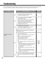
Troubleshooting ............................................................................................................... 50
2
Preface
This unit (WJ-GXD400, WJ-GXD400/G) is an IP-network-ready decoder.
This unit receives video and audio data through the IP network and provides the data to external devices such as
monitors and speakers.
Images from up to 6 cameras can be simultaneously displayed with this unit. For major functions, refer to the
Installation Guide.
Refer to "Readme.txt" on the provided CD-ROM for supported devices.
About the User Manuals
There are 2 sets of operating instructions for the WJ-GXD400, WJ-GXD400/G as follows.
• Installation Guide: Explains how to install and connect devices.
• Setup Instructions (PDF): Explains how to perform the settings of this unit using a PC via a network.
Adobe® Reader® is required to read these operating instructions (PDF) on the provided CD-ROM.
When the Adobe® Reader® is not installed on the PC, download the latest Adobe® Reader® from the Adobe web site
and install it.
"WJ-GXD400" or "GXD400" shown in the instructions and llustrations used in these operating instructions indicate
the WJ-GXD400, WJ-GXD400/G.
The screens used in these operating instructions show the case of NTSC model.
Refer to "Readme.txt" on the provided CD-ROM for further information including the dedicated software, its version,
and compatible cameras.
System Requirements for a PC
It is recommended to perform the settings of this unit using a PC that meets the following system requirements.
OS:
CPU:
Memory:
Monitor:
Network interface:
Web browser:
Other:
Microsoft® Windows Vista® Business 32-bit
Microsoft® Windows® XP Professional SP2*
Microsoft® Windows® XP Home Edition SP2*
Pentium® 4 3.0 GHz or faster
1 GB or more (A minimum of 512 MB memory is required when using Microsoft® Windows®
XP.)
Resolution: 1 024 x 768 pixels or more
Color: 24-bit True color or better
A 100/1 000 Mbps network interface card must be installed.
Windows® Internet Explorer® 7.0
Microsoft® Internet Explorer® 6.0 SP2*
It is necessary to read the operating instructions and use the software on the provided CDROM.
Adobe® Reader®: It is necessary to read the operating instructions on the provided CD-ROM.
* Microsoft® Internet Explorer® 6.0 SP2 is required when using Microsoft® Windows® XP Home Edition SP2 or
Microsoft® Windows® XP Professional SP2.
* Microsoft® Windows® XP Professional 64-bit Edition is not supported.
3
Note:
• When using a PC that does not meet the above requirements, displaying of images may become slow or the web
browser may become inoperable.
Trademarks and Registered Trademarks
• Adobe, Adobe logo and Reader are either registered trademarks or trademarks of Adobe Systems Incorporated
in the United States and/or other countries.
• Microsoft, Windows, Windows Vista, Internet Explorer, ActiveX and DirectX are either registered trademarks or
trademarks of Microsoft Corporation in the United States and other countries.
• Intel and Pentium are trademarks or registered trademarks of Intel Corporation or its subsidiaries in the United
States and other countries.
• HDMI, HDMI logo and High-Definition Multimedia Interface are trademarks or registered trademarks of HDMI
Licensing LLC.
• Other names of companies and products contained in these operating instructions may be trademarks or registered trademarks of their respective owners.
Copyright
Distributing, copying, disassembling, reverse compiling, reverse engineering, and also exporting in violation of export
laws of the software provided with this product, is expressly prohibited.
This product incorporates copy protection technology that is protected by U.S. and foreign patents, including patent
numbers 5,315,448 and 6,836,549, and other intellectual property rights. The use of Macrovision's copy protection
technology in the product must be authorized by Macrovision. Reverse engineering or disassembly is prohibited.
Abbreviations
The following abbreviations are used in these operating instructions.
Microsoft® Windows Vista® is described as Windows Vista.
Microsoft® Windows® XP Professional SP2 and Microsoft® Windows® XP Home Edition SP2 are described as
Windows XP.
4
Network Security
As you will use this product connected to a network, your attention is called to the following security risks.
• Leakage or theft of information through this product
• Use of this product for illegal operations by persons with malicious intent
• Interference with or stoppage of this product by persons with malicious intent
It is your responsibility to take precautions such as those described below to protect yourself against the above network security risks.
• Use this product in a network secured by a firewall, etc.
• If this product is connected to a network that includes PCs, make sure that the system is not infected by computer viruses or other malicious entities (using a regularly updated anti-virus program, anti-spyware program, etc.).
• Protect your network against unauthorized access by restricting users to those who log in with an authorized user
name and password.
• Apply measures such as user authentication to protect your network against leakage or theft of information,
including authentication information (user names and passwords) and DDNS server information.
5
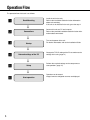
Operation Flow
The operation flow of this unit is as follows.
z
Rack Mounting
➜
x
Connections
Install the unit in the rack.
Refer to the Installation Guide for further information
about rack mounting.
If this unit is not installed in the rack, go to the step 2.
Connect this unit to a PC and cameras.
Refer to the provided Installation Guide for further information about connections.
➜
c
Startup
Turn on the power of the unit.
For further information, refer to the Installation Guide.
➜
v
Network settings of the PC
Change the TCP/IP setting of the PC to conform to the
settings of this unit. (page 12)
➜
b
Setup
Perform the required settings on the setup menu to
start operation. (page 14)
➜
n
6
Start operation
Operation can be started.
Images from the configured cameras are displayed.
Setup Menu Chart
Performing each setting on the setup menu should be completed in advance to operate this unit.
Refer to "Setup Window Call-up/Termination" (page 14) to display the setup menu.
Setup items
Description
Reference
page
Basic
Time & date
Date/time display format
Time display format
Time & date
Time zone
Summer time (daylight saving)
Summer time (daylight saving)
table
Default screen
Video/Audio output settings for the
default screen
Screen pattern
Camera CH designation
Audio output
Language
Language
16
Select a date display format.
Select a time display format.
Adjust the current time and date.
Specify the time zone.
Choose whether or not to configure summer time.
Specify the summer time starting year, month, day, and time,
and the summer time ending year, month, day and time.
18
Choose whether or not to automatically obtain and display
images when starting up this unit.
Select a screen pattern to be used when starting up this unit.
Specify which part of the screen the image obtained and displayed at startup is assigned.
Choose whether or not to provide the audio output received
from the camera when starting up this unit.
The audio output is not provided when the compression
method is set to JPEG.
19
Select a display language for the web browser.
Display
OSD
Camera title
Time & date
Screen ID
Optional info.
Screen ID
Time & date display
Border
Display mode
20
Specify the camera title position and adjust the position.
Specify the time & date position and adjust the position.
Specify the screen ID position and adjust the position.
Specify the optional information position and adjust the position.
Enter a screen ID displayed on the small window.
Choose whether or not to display the time of this unit.
Choose whether or not to display the border that splits the
screen and select a border color.
Select a display mode, either the full mode or trimming mode.
7
Setup items
Description
Reference
page
Event
Site alarm
Site alarm
Originating port number
Alarm message display
Output terminal
Alarm reset timer
Error notification
Error notification
Destination port
Retry times
Destination address
Output terminal
22
Choose whether or not to activate the site alarm.
Specify the port number to be used for receiving the site
alarm.
Choose whether or not to display the alarm message.
Choose whether or not to provide an alarm signal output from
the output terminal when an alarm signal is received.
Specify the period from alarm occurrence to alarm cancellation.
23
Choose whether or not to enable the error notification.
Specify the port number to which an error notification is transmitted when an error occurs.
Specify the retry number of the transmission to the PC when
transmission to the PC ends in failure.
Specify the address to which an error notification is transmitted when an error occurs.
Choose whether or not to provide an alarm signal output from
the output terminal when an error notification is received.
Schedule
Timetable
Display pattern
Schedule
Display pattern registration
Group
Image display on a 6-screen
Image display on a 3-screen
(PSL)
Image display on a 3-screen
(PSR)
Image display on a 1-screen
8
24
Select a display pattern from the registered patterns.
Perform the settings for the schedules by designating a day of
the week and time.
25
Select a number to be registered from the registered group
numbers and group sequence numbers.
Select a number to be registered from the registered camera
numbers and tour sequence numbers.
Select a number to be registered from the registered camera
numbers and tour sequence numbers.
Select a number to be registered from the registered camera
numbers and tour sequence numbers.
Select a number to be registered from the registered camera
numbers and tour sequence numbers.
Setup items
Description
Reference
page
Camera
NW camera setup
Camera
Live image source
Address
HTTP port
User name
Password
Recorder/Encoder (Model no.)
Recorder/Encoder (Camera CH
designation)
Camera title
Model no.
Compression
Image capture size
Transmission interval
Tour sequence
Camera no.
Preset camera no. (1-256)
Dwell time
Group sequence
Screen pattern
Group number
Dwell time
Registered pattern list
Screen pattern
Registered camera
26
Select a number assigned to the camera whose information
will be registered.
Obtain the information of the live image source.
Enter an IP address.
Enter a HTTP port number.
Enter a user name.
Enter a password.
Appears when information is obtained.
Select a camera channel according to the specified live image
source.
Displays the camera title by obtaining the information when
the camera title is specified. After obtaining the information,
the camera title can be edited.
Appears when information is obtained.
Select a compression method.
Select a resolution. Is selectable when the compression
method is set to JPEG.
Select an interval to update the image. Is selectable when the
compression method is set to JPEG.
29
Select a registered camera.
Enter the preset position of the camera to be moved at step
change.
Select a dwell time.
30
Select a screen pattern.
Select a group number from the registered groups.
Select a dwell time.
31
Select a screen pattern.
Select a registered camera.
Server
Proxy
Proxy
Server address
Port number
Exceptions
NTP
Time adjustment
NTP server address
Port number
Time adjustment interval
32
Choose whether or not to use a proxy server.
Enter the proxy server address.
Enter the port number of the proxy server.
Enter the IP address of the camera that does not use the
proxy server.
33
Select a time adjustment method for the NTP server.
Enter the IP address or host name of the NTP server.
Enter the port number of the NTP server.
Select an interval to update the time.
9
Setup items
Description
Reference
page
Network
Basic - IPv4 network
Network port
DHCP
IPv4 address
Subnet mask
Default gateway
Maintenance port
IPv4 address
Subnet mask
DNS
Primary server address
Secondary server address
HTTP port
Line speed
DDNS
DDNS
Host
User name
Password
Access interval
34
Choose whether or not to use DHCP.
Specify the IP address of the IPv4 network.
Specify the net mask in accordance with the network rules.
Configure the default gateway of the network.
34
Specify the IP address of the IPv4 network.
Specify the net mask in accordance with the network rules.
Select either automatic or manual manner to obtain the DNS
server address.
Specify the DNS server address.
Specify the DNS server address.
Specify the HTTP port number.
Specify the line speed for data transmission.
36
Choose whether or not to use DDNS.
Enter the host name to be used.
Enter the user name to log into the DDNS server.
Enter the password to log into the DDNS server.
Specify the interval to access the DDNS server to check the IP
address and host name.
User mng.
User authentication
User authentication
User name
Password
Retype password
Access level
User check
Host authentication
Host authentication
IP address
Access level
Host check
10
37
Choose whether or not to perform user authentication when
accessing this unit.
Enter a user name.
Enter a password.
Enter the password again to confirm the password entered
into [Password].
Assign the access level to the entered user name.
Displays the user registered under user authentication.
39
Choose whether or not to perform host authentication when
accessing this unit.
Enter the IP address to permit accessing to this unit.
Assign the access level to the entered user name.
Displays the host (IP address) registered under host authentication.
Description
Setup items
Reference
page
Maintenance
Product information - Version information
Software version
Hardware version
Product information - MAC address
Network port
Maintenance port
Product information - Serial no.
Product information - Internal thermal information
Current temperature
Highest temperature
Error log
Error log
Network log
Network log
Default reset
Reset to the default (Except the
network settings)
Reboot
Displays the software version.
Displays the hardware version.
41
41
Displays the MAC address of the network port.
Displays the MAC address of the maintenance port.
Displays the serial number of the main unit.
41
41
Displays the temperature inside the main unit.
Displays the highest temperature inside the main unit recorded
since turning on the power of this unit.
41
41
Displays the error occurrence date, time, and details.
42
Displays the error occurrence date, time, and details.
42
Initialize the setting data.
44
Restart this unit.
44
11
Network Setup
Network Settings of the PC
The TCP/IP setting of the PC shall be changed to conform to the settings of this unit. The IP address of the PC shall
be specified within the same subnet range as that of the network port of this unit to access this unit.
In these operating instructions, the settings are performed on Windows Vista as examples. Refer to the operating
instructions of the respective OS for further information.
Example:
To use this unit with the default settings (IP address: 192.168.0.250), the IP address of the PC should be
"192.168.0.XXX (XXX is a value between 2 and 254 except 250 (that is assigned to this unit)".
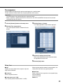
1 Log in to the PC as an administrator.
2 On the taskbar, click "Start", and then click the
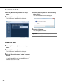
4 Click [View status].
The "Local Area Connection Status" window will be
displayed.
"Control Panel".
The control panel will be displayed.
3 Click [View network status and tasks].
The "Network and Sharing Center" window will be
displayed.
12
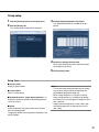
5 Click "Properties".
The "Local Area Connection Properties" window will
be displayed.
6 Select "Internet Protocol Version 4 (TCP/IPv4)",
and then click "Properties".
The "Internet Protocol Version 4 (TCP/IPv4)" window
will be displayed.
Note:
The "User Account Control" window will be displayed
depending on use or nonuse of a firewall.
7 Click "Use the following IP address" and enter
the IP address and the subnet mask.
8 Click the "OK" button and close the window.
13
Setup Window
Setup Window Call-up/Termination
This unit can be operated using a web browser installed on the PC.
1 Boot the PC.
2 Start the web browser.
3 Enter the IP address or URL assigned to this unit
4 Enter the user name and password registered on
this unit. Click the [Login] button.
The top page will be displayed.
into the [Address] box, and then press the
[Enter] key.
The authentication window will be displayed.
Even if "User authentication" is set to "Off", the
authentication window will be displayed.
Administration authentication is required to display
the setup window.
Important:
• Refer to a system administrator for the set IP
address of this unit.
• If "Host authentication" is set to "On" (page 39), this
unit cannot be accessed from the PC whose IP
address has not been registered with this unit.
Refer to a system administrator for further information.
• Do not attach "0" before the numbers when entering
IP address.
Example:
b 192.168.0.50
× 192.168.0.050
14
Important:
• Refer to a system administrator for the set user
name and password.
• Refer to page 37 for the descriptions of how to register users.
• The default user name and password are as follows.
User name: admin
Password: 12345
• To enhance the security, change the password for
an administrator before running the unit. It is recommended to change the password for the administrator periodically. Refer to page 37 for descriptions of
how to change the password.
• When the unit is being operated without changing
the user name and password, the pop-up window
saying that it is recommended to change the password will be displayed.
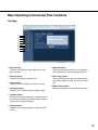
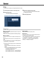
Major Operating Controls and Their Functions
Top Page
q
w
e
r
t
y
u
i
o
q [Basic] button
Performs the image and audio settings at time display or startup.
u [Network] button
Performs the network settings such as settings of
the IP address of this unit and gateway address.
w [Display] button
Performs the settings relating to OSD.
i [User mng.] button
Performs the settings for the user authentication/
host authentication to restrict access this unit from
PCs.
e [Event] button
Performs the action settings at event occurrence.
r [Schedule] button
Performs the schedule settings to display images.
o [Maintenance] button
Displays and initializes the information of this unit.
t [Camera] button
Performs the settings relating to the network such as
the camera IP addresses and port numbers and the
settings of the sequential display.
y [Server] button
Performs the settings relating to the proxy and NTP
servers.
15
Basic
Perform the settings for the basic operations of this unit.
Time & date
The settings of date and time are performed.
1 Click the [Basic] button on the setup menu.
2 Click the [Time & date] tab.
The "Time & date" window will be displayed.
3 Perform the settings for each item.
Refer to the following for further information about
the settings for each item.
4 Click the [Set] button.
Setup items
■ Date/time display format
Select a date format to be displayed from the following.
Example: (Ex. April 1, 2009)
DD/MM/YYYY: 01/04/2009
MM/DD/YYYY: 04/01/2009
DD/Mmm/YYYY: 01/Apr/2009
YYYY/MM/DD: 2009/04/01
Mmm/DD/YYYY: Apr/01/2009
Default: Mmm/DD/YYYY (NTSC model)
DD/MM/YYYY (PAL model)
■ Time display format
Select a time display format to be displayed from the following.
(Example for 3 o’clock in the afternoon)
12h: 03:00:00PM
24h: 15:00:00
Default: 12h (NTSC model)
24h (PAL model)
16
■ Time & date
Adjust the current time and date.
Select numbers for year, month, day, hour, minute and
second, and click the [Set] button. This unit operates
with the adjusted time from the moment of clicking.
2009-2035 (year)
/01-12 (month)
/01-31 (day)
/00-23 (hour)
/00-59 (minute)
/00-59 (second)
■ Time zone
Select the time zone of this unit.
■ Summer time (daylight saving)
Perform the settings for summer time from the following.
Out: Does not function.
Auto: Applies summer time in accordance with the setting of summer time. During summertime, the time
will be displayed with an asterisk (*).
Default: Auto
■ Summer time (daylight saving) table
Set the start (On)/end (Off) date and time for summer
time.
When the [Setup >>] button is clicked the following window will be displayed.
• Specify the summer time start date and time at [In]
and summer time end date and time at [Out].
• Up to 10 times and dates for switching to summer
time can be set.
• Click the [Set] button after completing the settings,
and close the window by clicking the [×] button at the
top right of the window.
17
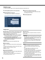
Default screen
The video and audio outputs can be automatically obtained at starting this unit.
1 Click the [Basic] button on the setup menu.
2 Click the [Default screen] tab.
The "Default screen" window will be displayed.
3 Perform the settings for each item.
Refer to the following for further information about
the settings for each item.
4 Click the [Set] button.
Setup items
■ Video/Audio output settings for the default screen
Determine whether or not to automatically obtain and
display images when starting up this unit.
Apply the below settings: Selection of the screen pattern and camera allows user to obtain and display
the configured image at starting this unit.
Maintain the previous operational state: The camera
image displayed immediately before restarting this
unit is obtained and displayed.
No output:
Default: Maintain the previous operational state
■ Screen pattern
Select a screen pattern to be used when starting up this
unit.
6-screen/3-screen (primary screen on the left)/3-screen
(primary screen on the right)/1-screen
Default: 6-screen
■ Camera CH designation
Specify which part of the screen the image obtained and
displayed at startup is assigned.
Select cameras whose images are to be displayed at
the image display positions 1 to 6.
18
■ Audio output
Select "On" or "Off" to determine whether or not to output the audio.
Important:
• The audio output is not provided when the compression method is set to JPEG. The audio output is provided only at the default screen.
• When the screen is split, the audio output is provided from the camera assigned to the image display
position 1.
Notes:
• Camera registration should be completed via
[Camera] and [NW camera] before camera selection.
• The audio output is available only from our
(Panasonic i-pro series) cameras.
• The audio output is provided only if the audio output
setting has been performed at the camera side.
• The schedule setting has higher priority if the schedule setting has been performed.
• Audio output and image output may sometimes not
be synchronized depending on the data (audio and
image) reception timing.
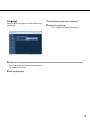
Language
Select the display language for the web browser from
the following.
1 Click the [Basic] button on the setup menu.
2 Click the [Language] tab.
The "Language" window will be displayed.
3 Perform the settings for each item.
Refer to the following for further information about
the settings for each item.
4 Click the [Set] button.
19
Display
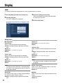
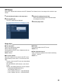
OSD
The settings of information displayed on the screen are performed in this section.
1 Click the [Display] button on the setup menu.
2 Click the [OSD] tab.
The "OSD" window will be displayed.
3 Perform the settings for each item.
Refer to the following for further information about
the settings for each item.
4 Click the [Set] button.
Setup items
■ OSD position
[Camera title]
Select a camera title position from the following.
Position: Off/Upper left/Upper right/Lower left/Lower
right
Default: Off
Adjustment: --/+1/+2/+3/+4/-1/-2/-3/-4
Default: -[Time & date]
Select a date and time position from the following:
Position: Off/Upper left/Upper right/Lower left/Lower
right
Default: Off
Adjustment: --/+1/+2/+3/+4/-1/-2/-3/-4
Default: -Note:
• If the date and time information is not provided from
the camera, even selecting other than "Off" does not
display date and time.
[Screen ID]
The settings of the screen ID in detail are performed on
the "Screen ID setup" window. (Page 21)
Position: Off/Upper left/Upper right/Lower left/Lower
right
20
Default: Off
Adjustment: --/+1/+2/+3/+4/-1/-2/-3/-4
Default: -[Optional info.]
Select an optional information position from the following.
Position: Off/Upper left/Upper right/Lower left/Lower
right
Default: Off
Adjustment: --/+1/+2/+3/+4/-1/-2/-3/-4
Default: -Note:
• The sequence number is displayed during sequential display.
■ Time & date display
Select "On" or "Off" to determine whether or not to display the time and date of this unit.
Default: On
■ Border
Select a color of the screen splitting border from the following.
Off/Black/Gray/White
Default: Off
■ Display mode
Select either the "Full screen" or "Trimmed screen".
When the display mode is toggled, restart this unit.
If edges of an image are chipped in the full screen,
change the mode to the trimmed screen.
Default: Full screen
Notes:
• Displayed characters may be overlapped depending
on the displayed position settings. If characters are
overlapped, the pop-up window is displayed.
• Check whether full resolution is available with the
connected monitor.
Important:
• If the time & date or border is always displayed, the
screen is susceptible to burn-in. Therefore, setting
the time & date or border to Off is recommended.
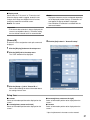
[Screen ID]
4 Click the [Set] button in "Screen ID setup".
A screen ID can be assigned to each split screen and
displayed.
1 Click the [Display] button on the setup menu.
2 Click the [OSD] tab in the setup menu.
The "OSD" window will be displayed.
3 Click the [Setup >>] tab in "Screen ID >>".
Refer to the following for further information about
the settings for each item.
Setup items
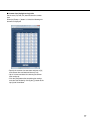
■ 6-screen
Select an information position to be displayed on the
screen.*
■ 3-screen(primary screen on the left)
Select an information position to be displayed on the
screen.*
■ 3-screen(primary screen on the right)
Select an information position to be displayed on the
screen.*
■ 1-screen
Select an information position to be displayed on the
screen.*
* Up to 4 alphanumeric characters can be entered.
21
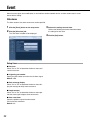
Event
When an event signal (alarm notification) is received from another network device, an alarm action starts in accordance with the setting.
Site alarm
The alarm action at site alarm occurrence can be specified.
1 Click the [Event] button on the setup menu.
2 Click the [Site alarm] tab.
The "Site alarm" window will be displayed.
Setup items
■ Site alarm
Select "On" or "Off" to determine whether or not to activate the site alarm.
■ Originating port number
Specify the port number to receive the site alarm signal.
Default: 1818
■ Alarm message display
Select "On" or "Off" to determine whether or not to display the message to notify event occurrence.
■ Output terminal
Select "On" or "Off" to determine whether or not to provide the alarm signal output at event occurrence.
■ Alarm reset timer
Select the period to cancel the alarm action.
Off/10s/20s/30s/1min/5min
Default: 20s
22
3 Perform the settings for each item.
Refer to the following for further information about
the settings for each item.
4 Click the [Set] button.
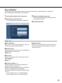
Error notification
When an error occurs, the setting to send the message to the previously registered addresses is performed.
Up to 3 destinations of notification can be registered.
1 Click the [Event] button on the setup menu.
2 Click the [Error notification] tab.
The "Error notification" window will be displayed.
3 Perform the settings for each item.
Refer to the following for further information about
the settings for each item.
4 Click the [Set] button.
Setup items
■ Error notification
Select "On" or "Off" to determine whether or not to activate the transmission of error notification.
■ Output terminal
Select "On" or "Off" to determine whether or not to provide the error notification signal output at error occurrence with this unit.
■ Destination port
Specify the port number to which an error notification is
transmitted when an error occurs.
Default: 8181
■ Retry times
Select the retry number of the transmission to the PC
from the following.
1/2/3 ...29/30
Default: 2
■ Destination address 1 - 3
Specify the address to which an error notification is
transmitted when an error occurs.
However, the following addresses are not available to
register as a destination of error notification.
0.XXX.XXX.XXX/XXX.XXX.XXX.0/XXX.XXX.XXX.255/
127.0.0.1
• Class D address (224.0.0.0 - 239.255.255.255)
• Class E address (240.0.0.0 - 255.255.255.255)
23
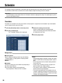
Schedule
The schedule setting is performed in accordance with the specified day of the week and time of the day.
It is possible to switch camera channels to be used to display images according to the set schedule.
Important:
• The audio output is not provided when the "Schedule" window is displayed for setup. The audio output is provided only at the default screen.
Timetable
Timetables are created for each day of the week, and a program is assigned to each timetable. Up to 6 timetables
can be created for each day of the week.
1 Click the [Schedule] button on the setup menu.
2 Click the [Timetable] tab.
The "Timetable" window will be displayed.
3 Perform the settings for each item.
Up to 6 schedule settings can be performed.
Refer to the following for further information about
the settings for each item.
4 Click the [Set] button.
Setup items
■ Display pattern
Select a registered display pattern from the following.
--/Display pattern 1/Display pattern 2/Display pattern
3/Display pattern 4
Default: -■ Schedule
Perform the settings for the schedules by designating a
day of the week and time.
Up to 6 schedule settings can be performed.
• Day unspecified: Check the "24h" checkbox.
24
Notes:
• Before display pattern selection, register the display
pattern via [Schedule] and [Display pattern registration].
• Be sure to perform each schedule setting between
00:00 and 24:00.
• If two or more schedules coincide, a higher numbered schedule has a higher priority.
• The entered 1-week schedule is displayed with a
band chart below the [Set] button.
• Even when it passed time of a timetable of the set
schedule, displaying of images will continue according to the setting of the previous schedule until other
schedule start displaying images.
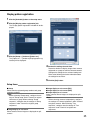
Display pattern registration
1 Click the [Schedule] button on the setup menu.
2 Click the [Display pattern registration] tab.
The "Display pattern registration" window will be displayed.
3 Click the [Setup >>] button of [Pattern no.].
The [Pattern no.: b] window of [Display pattern registration] will be displayed.
4 Perform the settings for each item.
Determine whether to display images from cameras
registered as a group or from the selected cameras.
Configure the settings for the selected setting item.
Refer to the following for further information about
the settings for each item.
5 Click the [Set] button.
Setup items
■ Group
Select from the registered group numbers and group
sequence numbers.
Note:
• Before selecting "Group setup", configure the settings of "Group setup" under "Camera" to register
cameras as a group. When selecting "Group
sequence", configure also the settings of "Group
sequence" under "Camera" to register group
sequences.
■ Image display on a 6-screen
Select cameras whose images are displayed on split
screens.
■ Image display on a 3-screen (PSL)
■ Image display on a 3-screen (PSR)
■ Image display on a 1-screen
Select cameras whose images are displayed on split
screens.
Note:
• Before selecting cameras independently, configure
the settings of "Camera registration" under "Camera"
to register cameras. When selecting "Tour
sequence", configure also the settings of "Tour
sequence" under "Camera" to register tour
sequences.
25
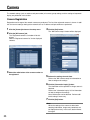
Camera
The network settings (such as address and port number) of cameras, group settings, and the settings of sequential
display are performed in this section.
Camera Registration
Registration and change of the network camera are performed. The list of the registered cameras is shown. In addition, the camera settings relating to the network such as IP address and port number are performed.
1 Click the [Camera] button on the setup menu.
2 Click the [NW camera] tab.
4 Click the [Set] button.
The "NW camera setup" window will be displayed.
The "Registered camera list" window will be displayed.
Refer to "Registered camera list" for the displayed
contents.
3 Select the radio button of the camera number to
be registered.
5 Perform the settings for each item.
Refer to the "NW camera setup" for information on
how to configure the settings.
6 Click the [Information inquiry] button.
The information of the specified live image source is
obtained.
Refer to the "Information inquiry list" for information
on how to configure the settings.
Not all information can be obtained. Perform additional settings if necessary.
7 Click the [Set] button.
Note:
When the settings of the camera is edited after
obtaining information, images may sometimes not
be displayed correctly. In this case, obtain information again.
26
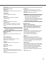
Setup items
■ Registered camera list
[Camera no.]
Displays the camera number. Up to 256 cameras can
be registered.
[Camera title]
Displays the registered camera titles.
[Model no.]
Displays the model number of the registered
camera/encoder.
[Address]
Displays the IP address of the registered
camera/encoder.
When "Via a recorder" is selected for "Live image
source", the IP address of the recorder will be displayed.
Note:
• To delete the information, select the camera number
and click the [Delete] button.
■ NW camera setup
[Camera]
Select a camera number whose information is registered.
[Live image source]
Select a live image source.
From a camera directly/Encoder/Via a recorder
Default: From a camera directly
[Address]
Enter the IP address of the live image source.
[HTTP port]
Enter a HTTP port number.
Default: 80
[User name]
Enter the user name assigned to the device of a live
image source when user authentication is set to "On" at
the device.
Enter up to 32 alphanumeric characters.
[Password]
Enter the password assigned to the device of a live
image source when user authentication is set to "On" at
the device.
Enter up to 32 alphanumeric characters.
Important:
• When using a camera other than Panasonic i-pro
series, select "Via a recorder" for "Live image
source". In this case, select "JPEG" for
"Compression".Refer to the operating instructions of
the recorder in use for further information on how to
configure the settings of the recorder.
■ Information list
[Model no. (Recorder/Encoder)]
Displays the model number of the recorder or encoder.
[Camera CH designation (Recorder/Encoder)]
Select camera channels of the device used as a live
image source.
[Camera title]
Displays the camera title after obtaining the information
if the camera title is assigned to the target device.
This item can be entered and edited.
Up to 16 characters in one byte/two bytes
[Model no.]
Displays the model number after information is
obtained. When routed through the recorder, the model
number of the camera/encoder connected ahead. When
the camera is directly connected, the model number of
the camera is displayed.
[Compression]
Select a compression method. The selectable compression method varies with the model of the camera whose
information is obtained. When routed through the
recorder, the compression method is decided depending on the device of the information source.
The compression method is selectable from the following:
JPEG/MPEG-4/H.264
27
[Image capture size*]
Select an image capture size. Image capture size can
be selected only when "JPEG" is selected for
"Compression".
Default: Auto
[Transmission interval]
Select a transmission interval when the compression
method is set to JPEG.
The higher the value of ips (images per second) is, the
shorter the transmission interval is.
Auto/0.1ips/0.2ips/0.3ips/0.5ips/1ips/2ips/3ips/
5ips/10ips/15ips/30ips
Default: Auto
For NP472/NW474/NS320 (NTSC model), the transmission interval is selectable from the following:
Auto/1ips/ 2ips/3ips/5ips/10ips/15ips/30ips
Default: Auto
Important:
• When "Via a recorder" is selected for "Live image
source", the image capture size and the refresh
interval will be dependent on the settings of the camera. The settings configured on the decoder will not
be applied. Confirm that the settings of the recorder
and the camera.
• When camera images via the recorder are displayed
in the VGA size, the resolution of the camera shall
be set to "VGA" or "QVGA".
* The resolution is selectable from the following:
Auto/QVGA(320x240)/VGA(640x480)/768x576 /4
VGA(1280x960)
Auto: Select a resolution in accordance with the
screen size.
QVGA(320x240): 320 x 240 pixels resolution
VGA(640x480): 640 x 480 pixels resolution
768x576: 768 x 576 pixels resolution
4VGA(1280x960): 1280 x 960 pixels resolution
The resolution varies with the model of the camera.
28
Notes:
• All options are displayed when the compression
method supported by the target device is unknown.
• Images with the resolution of 4 VGA (1280 x 960)
cannot be displayed in the reduced size of VGA (640
x 480).
• When trying to display images from a camera that
can transmit two streams of H.264 or MPEG-4, this
unit will automatically select either of streams
according to the resolution setting. When the same
resolution is set for both streams on the camera,
stream 1 will automatically be selected.
Tour sequence
Camera images are automatically switched and displayed in a specified order.
The tour sequence function works with the preset positions of the camera.
Important:
• The audio output is not provided during the sequential display.
• When a sequence is performed with two or more devices, the JPEG and MPEG-4 formats shall not be used
simultaneously with one camera.
1 Click the [Camera] button on the setup menu.
2 Click the [Tour sequence] tab.
3 Click the [Setup >>] button.
The "Step registration" window will be displayed.
The "Tour sequence number" window will be displayed.
4 Perform the settings for each item.
Refer to the following for further information about
the registrations for each item.
5 Click the [Set] button.
Setup items
■ Step
Displays the step number of the sequence. Up to 64
steps can be contained.
■ Camera no.
Select a registered camera.
■ Preset camera no. (1-256)
Enter a preset position number (blank, 1 to 256).
When no preset position number is entered (blank), the
camera does not move to any preset position.
■ Dwell time
Select an interval time to go to the next sequential step
from the following.
3s/5s/10s/15s/20s
Default: 3s
29
Group sequence
Live images from the camera/encoder/recorder on all the screens are simultaneously switched and displayed in the
3-screen/6-screen modes. The camera preset position cannot be selected during the group sequence.
1 Click the [Camera] button on the setup menu.
2 Click the [Group sequence] tab.
3 Click the [Setup >>] button.
The "Step registration" window will be displayed.
The "Group sequence number" window will be displayed.
4 Perform the settings for each item.
Refer to the following for further information about
the registrations for each item.
5 Click the [Set] button.
The specified values are stored.
Setup items
■ Screen pattern
Select a screen pattern.
6-screen/3-screen (primary screen on the left)/3-screen
(primary screen on the right)
■ Step
Displays the step number of the sequence. Up to 64
steps can be contained.
■ Group number
Displays the registered camera group number.
30
■ Dwell time
Select an interval time to go to the next sequential step
from the following.
3s/5s/10s/15s/20s
Note:
• Group registration should be completed via
[Camera] and [Group setup] before group number
selection.
Group setup
1 Click the [Camera] button on the setup menu.
2 Click the [Group] tab.
3 Click the [Registered pattern list] button.
The "Registered pattern list" window will be displayed.
The "Group setup" window will be displayed.
4 Perform the settings for each item.
Refer to the following for further information about
the settings for each item.
5 Click the [Set] button.
Setup items
■ Group number
Display a group number.
■ Screen pattern
Select a screen pattern.
■ Registered camera - Image display position 1 - 6
Assign the registered cameras to the display positions
1-6 on the screen.
■ Delete
Check the boxes of the group number to be deleted.
Click the [Delete] button.
To apply the deletion to the registered information, click
the [Set] button.
Note:
• To view the image display position from the configured camera, see the reference information displayed below [Registered group list].
• When "Group Sequence" is selected, a camera
image is displayed only in 1 position even though
the camera CH is set to display the images in more
than 1 position.
• Images with the resolution of 4 VGA (1280 x 960)
cannot be displayed in the reduced size of VGA
(640 x 480).
31
Server
Proxy
The proxy server settings can be performed with this menu.
1 Click the [Server] button on the setup menu.
2 Click the [Proxy] tab.
The "Proxy" window will be displayed.
3 Perform the settings for each item.
Refer to the following for further information about
the settings for each item.
4 Click the [Set] button.
Setup items
■ Proxy setup use
Select "On" or "Off" to determine whether or not to use
the proxy server.
When "On" is selected, perform the following settings.
■ Server address
Enter the server name or IP address of the proxy server. *1
When entering a server name, it is necessary to use a
DNS.
Up to 255 alphanumeric characters including hyphens
(-) and periods (.) can be entered.
*1The entry rules for the proxy server are shown below.
• At IPv4 entry
XXX.XXX.XXX.XXX (XXX indicates a value from 0
to 255.)
However, the following addresses are not available.
• 0.XXX.XXX.XXX/XXX.XXX.XXX.0/
XXX.XXX.XXX.255/127.0.0.1
• Class D address (224.0.0.0 - 239.255.255.255)
• Class E address (240.0.0.0 - 255.255.255.255)
32
■ Port number
Enter a port number of a proxy server.
■ Exceptions
Enter the set address of the network camera.Enter the
IP address of the excluded camera.
Up to 128 alphanumeric characters including asterisks
(*), semicolons (;) and periods (.) can be entered.
A semicolon (;) is used for dividing the addresses.
Entering "*" validates all numbers.
NTP Server
When time is adjusted with reference to the NTP (Network Time Protocol) server, the settings in this section are performed.
1 Click the [Server] button on the setup menu.
2 Click the [NTP] tab.
The "NTP" window will be displayed.
3 Perform the settings for each item.
Refer to the following for further information about
the settings for each item.
4 Click the [Set] button.
Setup items
■ Time adjustment
Select a time adjustment method.
Manual: Manual adjustment
Synchronization with NTP server: Adjustment with use
of the NTP server
Default: Manual
■ NTP server address
Enter the IP address or host name for the NTP server.
When entering a server name, it is necessary to use a
DNS.
The entry rules for the NTP server are shown below.
• At IPv4 entry
XXX.XXX.XXX.XXX (XXX indicates a value from 0
to 255.)
However, the following addresses are not available.
• 0.XXX.XXX.XXX/XXX.XXX.XXX.0/
XXX.XXX.XXX.255/127.0.0.1
• Class D address (224.0.0.0 - 239.255.255.255)
• Class E address (240.0.0.0 - 255.255.255.255)
■ NTP Port
Enter a port number of the NTP server.
Default: 123
■ Time adjustment interval
Select an interval to update the time from the following.
1h/2h/3h.....23h/24h
Default: 1h
33
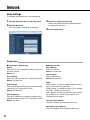
Network
Basic Settings
The network configuration for this unit is performed.
1 Click the [Network] button on the setup menu.
2 Click the [Basic] tab.
The "IPv4 network" window will be displayed.
3 Perform the settings for each item.
Refer to the following for further information about
the settings for each item.
4 Click the [Set] button.
Setup items
■ IPv4 network - Network port
[DHCP]
Select "On" or "Off" to determine whether or not to use
the DHCP function.
Default: Off
[IPv4 address]
Enter an IP address when "Off" is selected for "DHCP".
Default: 192.168.0.250
[Subnet mask]
Enter a subnet mask according to the network configuration when "Off" is selected for "DHCP".
Default: 255.255.255.0
[Default gateway]
Enter the IP address of the gateway according to the
network environment when "Off" is selected for "DHCP".
Default: 192.168.0.1
■ Maintenance port
[IPv4 address]
Enter an IP address.
Default: 192.168.2.250
[Subnet mask]
Enter a subnet mask.
Default: 255.255.255.0
[DNS]
Select "Manual" or "Auto" to enable IP address searching by the host name using the DNS.
Selecting "Auto" is available only when "On" is selected
for "DHCP" (using the DHCP server).
When "Manual" is selected for the DNS, enter the DNS
server addresses in "Primary server address" and
"Secondary server address".
[Primary server address]
Enter the IP address of the primary DNS server.
[Secondary server address]
Enter the IP address of the secondary DNS server.
34
[HTTP port]
A number from 1 - 65535 is available. Under normal
conditions, assign 80 to the number.
Default: 80
Notes:
• Depending on the network settings of the LAN or
Internet service provider, network communication
may not be established if the http port number has
been changed. In this case, refer to the administrator of the network.
• The following port numbers and the port numbers
used for the site alarm settings are unavailable for
the HTTP port number.
20, 21, 23, 25, 42, 53, 67, 68, 69, 110, 123, 161,
162, 995, 10669, 10670
[Line speed]
The following are available for "Line speed".
Auto/1000M-Full/100M-Full/100M-Half/10M-Full/
10M-Half
Default: Auto
Important:
• The network settings for each port (network
port/maintenance port) should be configured with a
different subnet.
35
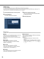
DDNS Setup
The settings are performed to use the DDNS (Dynamic Domain Name System).
Use of the DDNS function provides access with "The host name registered with the DDNS server. nmdns.net". To
receive the service, connection to the dedicated server is required.
1 Click the [Network] button on the setup menu.
2 Click the [DDNS] tab.
The "DDNS" window will be displayed.
3 Perform the settings for each item.
Refer to the following for further information about
the settings for each item.
4 Click the [Set] button.
Setup items
■ DDNS
Select "On" or "Off" to determine whether or not to use
the DDNS (Dynamic Domain Name Server).
When "On" is selected, perform the following settings.
Default: Off
■ Host name
Enter a host name registered in the DDNS.
Enter up to 64 alphanumeric characters including
hyphens (-) and periods (.).
■ User name
Enter a user name registered in the DDNS.
Enter up to 32 alphanumeric or symbolic characters
except for colons (:) and semicolons (;).*1
■ Password
Enter a password respective to the entered user name.
Enter up to 32 alphanumeric characters. *1
36
■ Access interval
Select an interval to update the DNS from the following:
1min/10min/30min/1h/6h/24h
Default: 1h
*1 The following alphanumeric characters can be
entered.
ABCDEFGHIJKLMNOPQRSTUVWX
YZabcdefghijklmnopqrstuvwxyz01
2 3 4 5 6 7 8 9 ! " # $ % ' ( ) * + , - . / :; < = > ? @ [ \ ]
^_`{|}~
User Management [User mng.]
The settings for the user authentication/host authentication are performed to restrict access this unit from PCs.
It is possible to restrict access this unit from users/hosts (PCs) by registering users and hosts (PCs) who can access
this unit in advance when "On" is selected for the user authentication and the host authentication.
User authentication
The information settings (change of user name and password, access level, etc.) of the user that operates this unit
are performed.
Up to 32 user information entries can be registered.
1 Click the [User mng.] button on the setup menu.
2 Click the [User authentication] tab.
The "User authentication" window will be displayed.
3 Perform the settings for each item.
The user name, password, password confirmation,
and access level can be specified.
Refer to the following for further information about
the settings for each item.
4 Click the [Set] button after completing the settings.
5 If user registration is continued, repeat the steps
3 and 4.
6 Select "On" or "Off" to determine whether or not
to authenticate the user.
Refer to the following for further information about
the settings for each item.
7 Click the [Set] button.
Setup items
■ User authentication
Select "On" or "Off" to determine whether or not to
authenticate the user.
■ User name
Enter a user name.
Enter up to 32 alphanumeric characters.
■ Password
Enter a password.
Enter 4 to 32 alphanumeric characters for a password.
Notes:
• Set a unique password, not something that would be
easily guessed by a third person. The password also
should be memorable.
• To enhance the security, change the password for
an administrator periodically.
■ Retype password
Reenter the password entered into [Password].
■ Access level
Select an access level.
Users whose access level is "Administrator" can access
the setup menu.
The settings for "Live image display" are for functions
that are not described in these operating instructions
and they are for expansion of external control interface.
It is impossible to access to the setup menu of these
functions.
1. Administrator/2. Live only
Default: 2. Live only
37
■ User check
It is possible to check the user names registered for the
user authentication.
To delete the displayed user, click the [Delete] button.
Important:
• When the user name already in use is selected and
the [Set] button is clicked, it will be overwritten.
Deletion of user information [User check]
1 Click the [User mng.] button on the setup menu.
2 Click the [User authentication] tab.
The "User authentication" window will be displayed.
3 Click the [C] button in "User check".
The user name registered under user authentication
can be viewed.
4 Click the [Delete] button.
The user selected in "User check" can be deleted.
38
Host authentication
The information of a PC (host) is registered, which accesses this unit via a network such as a LAN.
Up to 32 hosts can be registered.
1 Click the [User mng.] button on the setup menu.
2 Click the [Host authentication] tab.
The "Host authentication" window will be displayed.
3 Perform the settings for each item.
Set the IP address and the access level.
Refer to the following for further information about
the settings for each item.
4 Click the [Set] button.
5 Select "On" or "Off" to determine whether or not
to authenticate hosts.
6 Click the [Set] button.
Setup items
■ Host authentication
Select "On" or "Off" to determine whether or not to
authenticate the host.
■ IP address
Enter the IP address to permit accessing to this unit.
The host name cannot be specified.
■ Access level
Select an access level. The setup window can be
accessed through the host with the administrator level.
The settings for "Live image display" are for functions
that are not described in these operating instructions
and they are for expansion of external control interface.
It is impossible to access to the setup menu of these
functions.
1. Administrator/2. Live only
Default: 2. Live only
■ Host check
Displays the registered IP addresses by clicking [C].
The display type of the IP address is "Registered IP
address [access level]".
To delete the displayed IP address, click the [Delete]
button.
Important:
• The IP address and access level of the PC with
access permission shall be registered before the
setting of host authentication. If host authentication
is set to "On" before registration, the PC cannot
access to this unit.
• Clicking the "Set" button after entry of the registered
IP address provides overwriting of the IP address
information (access level).
39
Deletion of host information
1 Click the [User mng.] button on the setup menu.
2 Click the [Host authentication] tab.
The "Host authentication" window will be displayed.
3 Click the [C] button in "Host check".
The IP address registered under host authentication
can be viewed.
4 Click the [Delete] button.
The IP address selected in [Host check] is deleted.
40
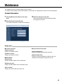
Maintenance
The conditions of this unit and the network can be checked.
The software and hardware versions, MAC address, serial number, and temperature inside the unit will be displayed.
Product Information
1 Click the [Maintenance] button on the setup
menu.
2 Click the [Product information] tab.
3 Check the settings for each item.
Refer to the following for further information about
the settings for each item.
The "Product information" window will be displayed.
Setup items
■ Version information
[Software version]
Displays the software version.
[Hardware version]
Displays the hardware version.
■ MAC address
[Network port]
Displays the MAC address of the network port.
■ Internal thermal information
[Current temperature]
Displays the temperature inside the main unit.
[Highest temperature]
Displays the highest temperature inside the main unit
recorded since turning on the power of this unit.
[Maintenance port]
Displays the MAC address of the maintenance port.
[Serial number]
Displays the serial number of the main unit.
41
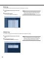
Error Log
The error logs (occurrence date and error details) will be displayed in list form.
1 Click the [Maintenance] button on the setup
menu.
2 Click the [Error log] tab.
The "Error log" window will be displayed.
Note:
• Up to 100 error logs can be kept. When more than
100 error logs are filed, the older error logs will be
overwritten by the newer error logs.
Network Log
The network error logs (occurrence date and error details) will be displayed in list form.
1 Click the [Maintenance] button on the setup
menu.
2 Click the [Network log] tab.
The "Network log" window will be displayed.
42
Note:
• Up to 1 000 network error logs can be kept. When
more than 1 000 error logs are filed, the older error
logs will be overwritten by the newer error logs.
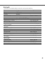
Error log list
The following are the descriptions about the contents of the error log and the network log.
Error
Error log
Network log
Restart
PWR ON
–
Reboot by the system error
SYSTEM REBOOT
–
Fan warning
FAN ERROR
–
Thermal error warning
THERMAL ERROR
–
Network link error
–
NETWORK LINK ERROR
Network camera error detection
CAM xxx COMMUNICATION ERROR
–
Network camera error recovery
CAM xxx COMMUNICATION RECOVERED
–
Password error for HTTP user name
–
<HTTP> USER_PASS_ERR
HTTP request invalid
–
<HTTP> REQUEST_ERR
Other errors for HTTP
–
<HTTP>OTHER_ERR
No response from an address of
Panasonic alarm protocol
–
PANASONIC_ALM_RES_ERR
Other errors for a address of Panasonic –
alarm protocol
PANASONIC_ALM_OTHER_ERR
No response from the DDNS server
<DDNS>SVR_ERR
–
Password error for DDNS user name
–
<DDNS>USER_PASS_ERR
DDNS IP address update error
–
<DDNS>IP_ADD_UPDATE_ERR
Other error for DDNS
–
<DDNS>OTHER_ERR
Having IP address complete
–
<DHCP>IP_ADD_OK
DHCP IP address registration failure
–
<DHCP>IP_ADD_ENT_ERR
Synchronization with the NTP
server complete
–
<NTP>GET_TIME_OK
Failed to resolve NTP server
address from DNS
–
<NTP>SVR_ADD_ERR
Failed to adust the time
–
<NTP>SET_TIME_ERR
No response from the NTP server
–
<NTP>SVR_ERR
Time from the NTP server is invalid
–
<NTP>TIME_INVALID
Other error for NTP
–
<NTP>OTHER_ERR
43
Reset to the Default
1 Click the [Maintenance] button on the setup
menu.
2 Click the [Default reset] tab.
3 Click the [Execute] button in "Reset the settings
to the default".
The confirmation window will be displayed.
The "Default reset" window will be displayed.
4 Click the [OK] button.
The setting data is initialized.
Important:
• The network settings are not initialized.
Restart this Unit
1 Click the [Maintenance] button on the setup
menu.
2 Click the [Default reset] tab.
The "Default reset" window will be displayed.
3 Click the [Execute] button in "Reboot" to restart
this unit.
It is impossible to operate this unit for approximately
1 minute immediately after the restart because initialization starts at the restart.
44
Viewing
Live Image Reception
Live images are received from the camera or encoder.
If a camera manufactured by other than Panasonic is used, live images will be received via the network disk
recorder.
The following transmission methods (protocols) are supported depending on media types.
MPEG-4/H.264 Media transmission: RTP multicast/unicast
JPEG Media transmission: HTTP-Push
Note:
• When displaying images on a 6-screen, the maximum image capture size of each screen is VGA size. When the
setting is configured in order to display images larger than VGA for each area of 6-screen, images may not be
displayed properly.
• When displaying images on a 3-screen, images larger than VGA can be displayed in the primary screen. When
the setting is configured in order to display images larger than VGA not for the primary screen or configured to
display images on 2 or more screens, images may not be displayed properly.
Live Audio Reception
A live audio stream is received from the camera, encoder or recorder.
The live audio reception can handle 1 audio stream. Two or more audio streams cannot be handled.
The live audio reception is compliant with G. 726.
Important:
• The audio output is provided only at the default screen.
• The audio output is not provided when the schedule is displayed.
• The audio output is not provided when the compression method is set to JPEG.
• When receiving audio via a recorder, set the "Audio bit rate" setting of the camera to "32 kbps".
Note:
• The live audio reception dose not support the cameras manufactured by other than Panasonic. When the live
audio reception is performed, use Panasonic cameras.
• Audio output and image output may sometimes not be synchronized depending on the data (audio and image)
reception timing.
Change of Image and Screen Pattern
Refer to Schedule (page 24) for change of the image and screen pattern.
45
Screen Pattern
The images from up to 6 cameras can be displayed on 1 screen at the same time.
Images can be displayed with the pattern of 1-screen/3-screen/6-screen.
■ 1-screen
■ Border
The split border can be colored.
The border color is selectable from off, white, gray and
black.
■ 3-screen (primary screen on the left)
■ Alarm message display
• When this unit senses an alarm, the border of the
image from the camera where the alarm is occurring
is colored red.
• When an alarm occurs, the date, time, information of
alarm source will be displayed.
■ 3-screen (primary screen on the right)
■ Time & date
The date and time of this unit are displayed.
■ 6-screen
Time & date
46
Display Mode
There are 2 display modes, "Full screen" mode (full-resolution display) and the "Trimmed screen" mode (trimming
mode).
Normally, select "Full screen". When the displayed images do not fit in the screen even by adjusting the display settings of the monitor in use, select "Trimmed screen". In the "Trimmed screen" mode, however, images to be displayed in each screen will also be trimmed.
Notes:
• When displaying smaller images on a larger screen area e.g. displaying VGA images on a 4VGA screen area,
the images are enlarged to fit to the screen size.
• It is not possible to display larger images on a smaller screen area i.e. displaying 4VGA images on a VGA screen
area.
Sequence
Camera images are automatically switched and displayed in a specified order.
There are two types of sequences: tour sequence and group sequence.
Tour sequence
A live image on a split screen (individual small screen) can be automatically switched and displayed in a specified
order during displaying on a multi-screen (1-screen/3-screen/6-screen).
The scheduled timer can switch a sequence.
The following items can be specified in a sequence pattern.
Item
Tour sequence number
Camera no.
Preset camera no.(1-256)
Description
Displays the number to identify the tour sequence to be specified.
Displays the camera number to be connected to this unit.
Enter the preset position (1 to 256) of the camera to be moved at
step change.
Dwell time
Select an interval time to go to the next sequential step.
However, an interval time between each step shall be the same.
47
Group sequence
Live images on all the split screens can be automatically switched and displayed in a specified order during displaying on a multi-screen (3-screen/6-screen).
This function is available for live images from the camera, encoder and network disk recorder.
Operation will be restricted as follows.
• The screen pattern cannot be changed during a sequence operation.
• Image switching by the timer does not support preset positions.
The following items can be specified in a sequence pattern.
Item
Group sequence number
Screen pattern
Description
Displays the number to identify the group sequence to be specified.
Screen pattern (3-screen (primary screen on the left)/3-screen (primary screen on the right/6-screen)
Group number
Displays the group numbers in each step registered at default.
A group sequence will be implemented by sequentially switching
from step 1.
Dwell time
Select an interval time to go to the next sequential step (group).
However, an interval time between each step shall be the same.
The following items can be specified in group information.
Item
Group number
Description
Displays the number to identify the camera group to be registered
with this unit.
Group 1 to Group 64 are available to assign numbers to groups.
Screen pattern
Screen pattern (3-screen (primary screen on the left)/3-screen (primary screen on the right/6-screen)
Camera number displayed at
each image display position.
Select a number from camera numbers registered in the camera
setup section.
Schedule
Images are displayed according to the previously specified schedule.
Up to 6 schedules can be registered (page 24).
The following items can be specified in a schedule.
• A day of the week
• Start time and end time
• Display pattern
The following items can be specified in a display pattern.
• Screen pattern
• Camera selection for each split screen
48
Site alarm
Error Notification
When this unit receives an alarm notification from
another network device, the following are provided.
When device abnormality occurs or is detected, the following are provided.
(1) Transmission of error notification
The information about the error of this unit is transmitted to other devices through the error notification.
(1) Alarm message display
The message of the alarm reception is displayed on
the monitor.
The following contents are displayed in the alarm
message area of the monitor.
• Time and date
• Alarm source information
Note:
• When two or more alarms are received, the messages are displayed in an overwriting manner.
When an alarm is issued, which is related to the
image displayed on the screen at that moment, the
following information is displayed.
• The alarm occurrence image is enclosed with a
red border.
(2) Output terminal
If the output terminal is set to [ON], the output terminal switches to [Active].
(3) Alarm indicator
Lights up.
The following 2 methods are used to cancel an alarm.
(Restoration from alarm)
(1) When the specified timeout period by timercontrolled passes
(2) Message display
The error message is displayed on the monitor.
The error contents are displayed in the message
area of the monitor.
Note:
• When two or more errors occur, the messages are
displayed in an overwriting manner.
(3) Output terminal
If the output terminal is set to [ON], the output terminal switches to [Active].
(4) Error indicators 1 and 2
Blink
(5) Log
Error occurrences and detected histories are recorded and stored.
Note:
• When a new log is filed beyond the recordable
capacity, stored error logs are deleted in chronological order.
• Up to 100 error logs can be recorded.
• Up to 1 000 network logs can be recorded.
(2) When the contact input for restoration from
alarm is provided
Error operations
b: Yes, –: N/A
Transmission
of error
notification
Error 1
indicator
Error 2
indicator
Output
terminal
Message
display
FAN warning
–
–
b
b
b
Thermal error warning
–
–
b
b
b
Network link error
–
b
–
b
b
Network camera error
b
–
b
–
–
Network camera error recovery
b
–
–
–
–
Description of error
49
Troubleshooting
Check the following before requesting repair. Contact your dealer if a problem cannot be solved even after checking
and trying the solution or a problem is not described below, and when having a problem with installations.
Problem
Cannot access from the
browser.
Check item/Remedy
• Is the Ethernet cable firmly connected to the
100BASE-TX/1000BASE-T port?
–
• Is the connection indicator of the 100BASETX/1000BASE-T port lit?
When it is not lit, connection to a LAN is not established or a network is not working correctly.
Confirm that the connection indicator of the
100BASE-TX/1000BASE-T port is lit. Refer to a system administrator if it is not lit.
–
• Is the power of this unit turned on?
Check whether the power of this unit is turned on.
Confirm that the OPERATE indicator is lit.
–
Contact your system administrator to confirm that the
valid IP address is set.
34
• Is the valid IP address set?
Refer to a system administrator for further information.
Are you accessing the wrong IP address?
Check the connection as follows:
>ping "IP address of this unit"
If there is reply from this unit, the connection is normal.
If not, check the settings of the IP address and the
subnet mask.
• Set the mode switch No. 2 on the front panel to ON,
perform initialization by restarting this unit with the
reset switch, and return the IP address to
"192.168.0.250".
After initialization, set the mode switch No. 2 back
to OFF.
• Perform access from the maintenance port on the
front panel. The default IP address of the maintenance port is "192.168.2.250".
• Is the same IP address provided to other devices?
Refer to a system administrator for further information.
50
Reference
page
Page 12
of the
Installation
Guide
12
Problem
Some contents are not displayed on the browser.
No live image is displayed.
Check item/Remedy
• Reload the contents by pressing the [F5] key.
Reference
page
–
• Check the settings of [Camera] on the setup menu.
26
• Check the settings of [Basic] on the setup menu.
16
• Check the settings of IP address, subnet mask and
default gateway for them.
34
• If "On" is selected for "Proxy", MPEG-4/H.264 images
cannot be received or displayed. To view live images,
select "Off" for "Proxy" or use JPEG images.
MPEG/H.264 images are displayed when the device
capturing the image is located in the same network as
this unit regardless of whether the proxy setting is on or
off.
32
• When trying to display MPEG-4/H.264 images via the
Internet, images from the camera may not be displayed. Refer to the network administrator because of
the effects of the network devices including router setting.
–
• When displaying images via a recorder, images from
the specified camera channel of the specified
recorder cannot be displayed on multiple screens
simultaneously.
Check the settings of "Default screen", "Display pattern registration" and "Camera".
18, 25, 26
51
Problem
No live image is displayed.
Refresh of live images is
unstable.
The web browser is disconnected.
Network performance is
poor.
The password is forgotten.
52
Check item/Remedy
Reference
page
• When other devices obtain images from the cameras
and recorders, this product may fail to obtain and display images due to restrictions of the cameras and
the recorders.
• When displaying images on a 6-screen, the maximum image capture size of each screen is VGA
size. When the setting is configured in order to display images larger than VGA for each area of 6screen, images may not be displayed properly.
• When displaying images on a 3-screen, images larger than VGA can be displayed in the primary screen.
When the setting is configured in order to display
images larger than VGA not for the primary screen
or configured to display images on 2 or more
screens, images may not be displayed properly.
–
• When the settings of the camera is edited after
obtaining information, images may sometimes not be
displayed correctly. In this case, obtain information
again.
26
• The configured settings for transmission rate/recording rate may be beyond the maximum network performance.
Lower the value/rate of the settings relating to the network such as the transmission rate from cameras.
34
• The line speed settings may be not the same between
the unit and the hub, for example, 100M BASE-TX
Full for the unit and 100M BASE-TX half, etc.
Some hubs change the line speed automatically
depending on the network traffic and it may cause
configuration errors.
Check the line speed settings of both the unit and the
hub, and configure the line speed setting of both to
conform them.
–
• Set the mode switch No. 1 on the front panel to ON,
and perform initialization by restarting this unit with
the reset switch (All the setting data is initialized at
that time). After initialization, set the mode switch No.
1 back to OFF.
Page 12
of the
Installation
Guide
Problem
Check item/Remedy
Reference
page
The audio output is not provided.
• The audio output is not provided during the sequence
display (tour sequence/group sequence).
The audio output is not provided when the compression method is set to JPEG.
• The audio output is provided only at the default
screen.
• The audio output is not provided when the schedule is
displayed.
• When receiving audio via a recorder, set the "Audio
bit rate" setting of the camera to "32 kbps".
–
The resolution and transmission interval are not the
same as the specified values.
• The settings are recorder-dependent when images
are downloaded via the recorder, which disables the
settings of this unit. Check the settings of the recorder
and camera.
27
The clock of the camera is
not displayed.
• If the date and time information is not provided with
images from the camera, even selecting other than
"Off" for [OSD] – [Time & date] does not display date
and time.
20
The message "Cannot login." is displayed.
• Multiple users cannot access concurrently. When
other user is operating the setup menu, this message
will be displayed.
• When no operation is performed for a certain period
(30 minutes) after launching the web browser, the
user will be logged out forcibly. Access and log in
again.
• When the network communication is disconnected
and not established for a certain period (90 seconds)
after launching the web browser due to heavy network
traffic, the user will be logged out forcibly.Check the
network status and access later.
–
The message "Entered
information is incorrect" is
displayed at the settings of
default screen, display pattern registration (schedule),
or group setup (camera registration).
• Is an unregistered camera selected?
Check [NW camera].
• Is the area smaller than each area of 6-screen selected for images larger than VGA?
Check [NW camera].
26 - 28
53
For U.S. and Canadian fields:
For European and other fields:
Panasonic System Networks Company of America,
Unit of Panasonic Corporation of North America
http://panasonic.net
www.panasonic.com/business/
For customer support, call 1.800.528.6747
Three Panasonic Way, Secaucus, New Jersey 07094 U.S.A.
Importer's name and address to follow EU rules:
Panasonic Canada Inc.
Panasonic Testing Centre
Panasonic Marketing Europe GmbH
Winsbergring 15, 22525 Hamburg F.R.Germany
5770 Ambler Drive, Mississauga, Ontario, L4W 2T3 Canada
(905)624-5010
www.panasonic.ca
© Panasonic System Networks Co., Ltd. 2010
N0608-6010
3TR005599GAB
Printed in Japan