1
FV-08VQC5
FV-11VQC5
68
Centered/
9
11
11
11
12. Do not install with a method which is not approved in the instructions.
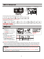
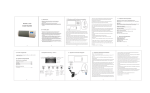
These Panasonic ventilating fan models are equipped with a motion sensor and a humidity
sensor that turn on automatically when motion is detected, when humidity increases rapidly,
or when humidity rises above a 30% ~ 80% relative humidity set-point. It is user-adjustable to
operate 0.5 ~ 60 minutes after the sensors are no longer detected.
s
a
3 7/8(98)
Motion sensor unit
Humidity sensor unit
11
Fan body
Junction box
Main control circuit
Red
White
Capacitor
White
Motor
White
Neutral
Black
Black
Live (VENT.)
Green
(Earth ground)
Yellow
Black
Red
(114 C Fuse in Motor)
lmpedance-protected
Motion sensor
AC120V
60Hz
(Power supply)
White
White
Humidity sensor
Black
Black
Green
Yellow
White
Red
Red
White
Adjustment
switch
Humidity setting Timer
Humidity
preset switch
Timer
preset switch
MIN
~30%
M
~80AX
%
MIN
~30%
MA
~80%X
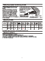
Humidity preset switch positions (Tolerance:±10%)
MIN ~MAX
~ 30%
~ 40%
~ 50%
~ 60%
~70%
~ 80%
Factory setting:~50% RH ("~" means "about")
Timer preset switch positions
Timer
Position
: refer to 0.5 minute
Panasonic ventilating fan
responds to:
(1) Motion sensor detectible
condition.
(2) Humidity sensor detectible
condition.
Motion sensor detectible
condition
The delay time is determined
by timer preset switch.
The unit continues running for
an adjustable duration
of 0.5 to 60 minutes, after
motion is no longer detected.
Room temperature is
25 (77 F).
Human
activity
Fan activity
Stop
Remains running
until the delay time
has passed
Humidity sensor detectible condition
(a) rapid to moderate humidity increases and (b) humidity above a 30% ~ 80% relative humidity
set-point. (a) and (b) are set with "HUMIDITY SETTING" adjustment. Fan may occasionally turn
on when environmental conditions change. The "TIMER" controls how long the fan remains on
(a) after rise in humidity and (b) humidity level is below the set-point decreasing about 5%RH.
1. If this unit is to be install over a tub or shower, for best results, locate it near the shower
head.
2. Long-time operation will influence the detecting precision as dust accumulates. Humidity
preset switch may need to be adjusted.
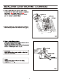
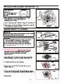
Motion sensor
unit
6
Motion sensor
unit
page 4
7
fix
(3 position) (Fig.6).
9. Adjust timer preset switch and humidity preset
switch (Fig.7). Refer to switch indication on page 5.
8
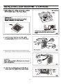
CENTERED/
9
4. Do not use cleaning sprays, solvents, or water on
or near the sensors.
Remove grille by pulling down the mounting spring
opposite the sensor lead.
10
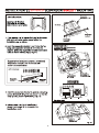
FV-08VQC5
15.5
815
FV-11VQC5
23.0
960
11
110
T0511-0
08VQC5420