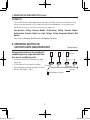
1
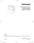
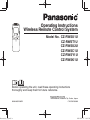
Operating Instructions
Wireless Remote Control System
Model No. CZ-RWSU1U
CZ-RWST1U
CZ-RWSU2U
CZ-RWSC1U
CZ-RWSY1U
CZ-RWSK1U
Before operating the unit, read these operating instructions
thoroughly and keep them for future reference.
85464609158012
Instruction_eng.indd a
1006 Kadoma, Kadoma City, Osaka, Japan
CV6233189680
2012/01/27 16:25:30
Instruction_eng.indd b
CONTENTS
1. IMPORTANT SAFETY INSTRUCTIONS ......................................1
2. NAMES AND OPERATIONS ........................................................2
3. INSTALLING BATTERIES.............................................................7
4. SETTING THE CURRENT TIME ..................................................8
5. OPERATION .................................................................................9
6. TIMER OPERATION ...................................................................11
7. ADJUSTING THE WIND DIRECTION ........................................13
8. OPERATING MULTIPLE IN/OUTDOOR UNITS
SIMULTANEOUSLY ....................................................................14
9. USING THE REMOTE CONTROLLER.......................................15
10. FOR BEST RESULTS...............................................................15
11. ADDRESSES............................................................................16
12. EMERGENCY OPERATION .....................................................19
13. MISCELLANEOUS SETTINGS ................................................21
14. BEFORE REQUESTING SERVICE..........................................22
15. SPECIFICATIONS ....................................................................23
2012/01/27 16:25:31
1. IMPORTANT SAFETY INSTRUCTIONS
Before using the system, be sure to read these
“IMPORTANT SAFETY INSTRUCTIONS”.
After reading this manual, save it in a convenient
place.
Electric shock or fire may result if an
inexperienced person performs any installation
procedures incorrectly.
Note:
• This device complies with Part 15 of the FCC
Rules. Operation is subject to the following
two conditions: (1) This device may not cause
harmful interference, and (2) this device must
accept any interference received, including
interference that may cause undesired
operation.
• This equipment has been tested and found
to comply with the limits for a Class B digital
device, pursuant to part 15 of the FCC Rules.
These limits are designed to provide reasonable
protection against harmful interference in
a residential installation. This equipment
generates, uses and can radiate radio
frequency energy and, if not installed and used
in accordance with the instructions, may cause
harmful interference to radio communications.
However, there is no guarantee that interference
will not occur in a particular installation. If this
equipment does cause harmful interference
to radio or television reception, which can be
determined by turning the equipment off and
on, the user is encouraged to try to correct the
interference by one or more of the following
measures:
• Reorient or relocate the receiving antenna.
• Increase the separation between the
equipment and receiver.
• Connect the equipment into an outlet on a
circuit different from that to which the receiver
is connected.
• Consult the dealer or an experienced radio/TV
technician for help.
• FCC Caution: To assure continued compliance,
follow the attached installation instructions.
Any changes or modifications not expressly
approved by the party responsible for
compliance could void the user’s authority to
operate this equipment.
Warning
Installation Precautions
•
•
Do not install yourself.
Installation should always be performed by your
dealer or a professional service provider.
Electric shock or fire may result if an
inexperienced person performs any installation
or wiring procedures incorrectly.
Use only specified air conditioners.
Always use only air conditions specified by the
dealer.
Precautions for Use
•
•
•
•
Do not touch switches with wet hands.
Electric shock and damage to the system can
result.
Protect the remote controller from water.
Damage to the system can result.
Stop the system and turn the power off if you
sense unusual smells or other irregularities.
Continuing operation when the system is out of
order can result in electric shock, fire, and
damage to the system. Contact your dealer.
Do not swallow the battery.
Moving and Repair Precautions
•
•
Instruction_eng.indd 1
Do not repair.
Never repair the system by yourself.
Contact your dealer before moving the system.
Contact your dealer or a professional service
provider about moving and reinstalling the system.
1
2012/01/27 16:25:31
2. NAMES AND OPERATIONS
REMOTE CONTROLLER
One remote controller can control a group of up to eight indoor units.
(See Page 14)
1.
Operation Display
Displays the operation status. (The figure
shows all the statuses.)
• The auto-flap display may be different,
depending on the installed unit. (See
Page 13)
2. Start/Stop button
Pressing this button once starts and pressing
again stops the operation.
3. Fan speed button
4. Swing/Wind Direction button
5. Timer setting button
Use for operating with a timer.
6. Reset button
Use this button after changing the batteries.
7. Cover
Press at the top center and then slide down.
8. Transmitter
9. Remote control sensor
Detects the temperature at the remote
controller when detection has been switched
to the remote controller by the sensor button.
10. Temperature setting buttons
Instruction_eng.indd 2
11. Filter button
CZ-RWSC1U
Press to turn off the filter lamp on the
receiver.
12. Mode Select button
Press to switch the operation mode.
13. Ventilation button
Use this when connected to an aftermarket
fan. Pressing this button starts and stops the
fan. When the air conditioner is started or
stopped, the fan starts or stops at the same
time. (
appears on the display of the
remote controller when the fan is operating.)
14. Address button
15. Sensor button
Use this when switching to detect the
temperature at the remote controller. At
shipping the default setting is set to detect
the temperature at the unit. At this time
is
shown on the display.
16. Clock button
Use this when setting the clock.
raises the temperature setting.
From this page on the names of remote control
buttons will be abbreviated as the illustration of
the “button”.
E.g.: Start/Stop button Æ
lowers the temperature setting.
2
2012/01/27 16:25:31
Instruction_eng.indd 3
REMOTE CONTROLLER
8
9
1
2
3
4
10
5
11
12
13
14
6
15
16
7
3
2012/01/27 16:25:31
2. NAMES AND OPERATIONS (Cont.)
RECEIVER
1.
2.
in conjunction with a wired remote controller
(sold separately). (Consult with the dealer
where the product was purchased about
making the settings.)
Test/On switch
This is used during service. It is not for
normal use.
Test Run/On switch
This is used during service. It is not for
normal use.
9. Address switch
Differentiate between incoming and outgoing
signals.
Note
Receiver
Receives the signal sent from the remote
controller.
Emergency operation button
Display lamps
When an error occurs, one of the lamps flashes. When a
display lamp is blinking, refer to “14. BEFORE
REQUESTING SERVICE”.
3.
4.
5.
6.
7.
8.
Instruction_eng.indd 4
Operating lamp
This lamp is lit when the unit is operating.
Timer lamp
This lamp is lit when the timer is set.
Standby lamp
• When the heater is working, the lamp
lights at the following times. When the
thermostat has operated during defrosting
at the time of the startup.
• The lamp flashes when an error occurs.
Filter lamp
This lamp is for notifying you when the filter
needs to be cleaned.
•
•
Swing button
Normal/Stop All switch
Use in the Normal position. It does not
operate in the Stop All position.
Remote control, main / remote control,
secondary, switch
In normal use this should be on remote
control, main. It is also possible to use both
If a heat pump model is being used, it will beep
twice and the operating lamp will light up on the
display; if the timer and standby lamps blink
alternately, a conflict between the heating and
cooling exists, so the unit cannot operate in the
desired mode. (On models that do not have Auto
function, even if Auto is selected, it works in the
same way.)
When the local operation is disabled by such as
the centralized control, and if the Start, Stop, Mode
or Temperature setting buttons are pressed, the
unit will beep five times and the change will not be
made.
4
2012/01/27 16:25:32
RECEIVER
CZ-RWSU1U
CZ-RWST1U
2
1
2
3
4
5
3
5
1
CZ-RWSY1U
CZ-RWSC1U
1
2
4
1
7
2
3
4
5
8
9
3
4
5
6
Instruction_eng.indd 5
5
2012/01/27 16:25:32
2. NAMES AND OPERATIONS (Cont.)
RECEIVER
CZ-RWSU2U
3
4
Display
5
1
2
Operation Panel
8
9
7
Indoor Unit (CZ-RWSK1U)
Instruction_eng.indd 6
3
4
5
2
6
2012/01/27 16:25:32
3. INSTALLING BATTERIES
1. Remove the cover.
2. Insert two AAA alkaline batteries.
Put the batteries in with the polarity [+/–] as shown in the
figure.
3. Gently insert one end of an unfolded paper clip
(or a similar object that can fit) into the Reset hole
and press the reset button inside the hole and
then put the cover back on.
Reset hole
Note
•
•
•
•
•
Change the batteries when the display of the remote controller
gets weak or if it will not work unless close to the receiver.
(Alkaline batteries generally last about one year.)
When changing batteries, always use two fresh batteries of the
same make.
If the remote controller will not be used for a long period of
time, remove the batteries.
Please dispose of batteries appropriately.
After changing the batteries, follow the procedures on the next
page to reset the current time.
Cover
HOW TO REMOVE BATTERIES
1. Remove the cover.
2. Press the battery toward the negative end and
lift it out by its positive end. (As shown at right)
3. Remove the other battery in the same way.
Note
•
Dispose of the used batteries at the designated location in
compliance with the applicable local ordinances.
•
•
Do not swallow the battery.
After removing the battery from remote controller, keep it away from the reach of children.
The battery can cause death by suffocation if swallowed.
When inserting the battery, make sure the polarities (+ and -) are correct.
Warning
•
Instruction_eng.indd 7
7
2012/01/27 16:25:32
4. SETTING THE CURRENT TIME
After changing the batteries and pressing reset, be sure to reset the
current time.
(When reset is pressed, the current time reverts to [
])
1. Press
for two seconds or more.
Once the clock displays starts blinking, the clock can be set.
2. Set the hour with
of the
/
.
If you press and hold the button, the time changes quickly.
3. Set the minutes with
/
of the
.
If you press and hold the button, the time changes quickly.
4. Pressing
completes the time setting.
• While you are setting the current time, the time display flashes but
the colon does not.
• If the buttons are not pressed for three minutes while setting the
current time, it is set to the displayed time.
Note
• When reset is pressed, the timer settings are deleted.
Instruction_eng.indd 8
2
3
1, 4
8
2012/01/27 16:25:32
5. OPERATION
Auto
, Dry , Cool , Fan
, Heat
Models that only provide the cooling function cannot operate in the auto or heating modes.
Power: Turn on the power of the indoor unit at least 14 hours
before operation.
1. Press .
2. Press
and select from among Auto , Heat , Dry ,
Cool and Fan .
3. Press and select the desired speed.
If set to Auto
, the fan speed switches automatically. (Auto does
not work when in the Fan mode.)
4. Press one of the
temperature.
MAX
MIN
Auto
80
62
Heat
78
60
86
64
/ Cool
Stop: Press
Instruction_eng.indd 9
3
buttons and set the desired
Temperature settings cannot be made when in the Fan mode.
Dry
1
4
2
.
When the unit is stopped with the remote controller, even though
the compressor of the outdoor unit stops, the fan on the outdoor
unit may continue to run for a while.
9
2012/01/27 16:25:32
5. OPERATION (Cont.)
If the unit is not heating very effectively with a Low fan speed
speed to High
or
Medium.
, switch the fan
Depending on the indoor unit being used, it may indicate a function that it does not have. (The fan
speed is set.)
If you cannot turn the air conditioner off in the normal way.
Disconnect the power to the indoor unit and contact the dealer where the product was purchased.
<Auto Operation>
If all the indoor units are identical in a cooling system and are under control as one group, it heats or
cools automatically via the differences between the set temperature and the room temperature.
<Dry Operation>
• Depending on the indoor unit used, the remote controller may have a [Dry] indicator on its display
even though the unit does not have the Dry function. (Same as cooler operation)
• When the room temperature approaches the temperature setting, the unit continues to start up or
stop automatically.
• When the drying mode stops operating, the indoor unit’s fan blows a gentle breeze in order to keep
the moisture from returning to the room at a minimum.
• Depending on the indoor unit used, and/or the temperature in the room, the fan speed may not be
adjustable.
• Depending on the unit used, when the outside air temperature is 59 °F or less, the dry function will
not operate.
Instruction_eng.indd 10
10
2012/01/27 16:25:33
6. TIMER OPERATION
• When setting the timer, make sure the current time on the remote controller is accurate.
• The timer’s clock can only be set when the display of the remote controller is ON.
• After setting the timer, put the remote controller in a place where its signal will reach the receiver of
the indoor unit. (When the time set for the timer is reached, a signal is sent from the remote
controller to Start/Stop the unit.)
Using the Timer
/
1. Press either
of the
being displayed, if you press
be set.
or
/
, and while the time is
again, a scheduled time can
The time last set on the timer is displayed.
“--:--“ indicates time to change the batteries.
2. Press either
desired time.
/
of the
or
and set the timer to the
Every time you press
, the time changes in 10 minute increments.
/
If you press and hold the button, the time changes quickly.
3. After setting the timer, if you press
, the time you set
changes to a steady display, indicating settings are complete.
Instruction_eng.indd 11
After the timer setting is displayed for three seconds, the display reverts to
the current time.
3
1, 2
11
2012/01/27 16:25:33
6. TIMER OPERATION (Cont.)
Combining ON and OFF Timers
• Setting the ON and OFF timers, respectively.
Checking the timer setting
• If you press either
/
for the
or the
, the scheduled time is displayed for four
seconds.
• When no timer setting has been made, it displays --:--. (Initial Setting)
Changing a timer setting
• Press
/
for the
for the timer again.
or the
, and then when the timer setting is displayed, press
/
Canceling a timer setting
• If you press [CANCEL], the timer setting is canceled.
• If you wish to cancel the setting for either the
or the
timer, press
timer and when the scheduled time is displayed, press [CANCEL].
/
or the desired
Using the same timer setting every day
• If you press
for 2 or more seconds, “
” is displayed and the ON timer or the OFF timer will
operate the unit at the same time every day.
• If you press
again for two seconds or more, “
” goes off and the timer operates just once.
Instruction_eng.indd 12
12
2012/01/27 16:25:34
7. ADJUSTING THE WIND DIRECTION
• Never try to manually move the flap (up-down wind direction plate) that is operated by the remote
controller.
• When the unit stops, the flap (up-down wind direction plate) automatically faces downwards.
• When the unit is in heating standby, the flap (up-down wind direction plate) faces upward. Also,
bear in mind that the flap starts swinging after the heating standby mode is released, but the
display on the remote controller indicates Auto Flap during standby heating as well.
CZ-RWSU1U/CZ-RWST1U/CZ-RWSU2U/
CZ-RWSY1U/Indoor Unit (CZ-RWSK1U)
Instruction_eng.indd 13
In the Heat Mode
Setting the Wind Direction
While the unit is operating, every time you press
direction the flap faces changes.
, the
Setting Flap to Swing
If you press
to set the flap (up-down wind direction
plate) in its most downward facing position, and then
press
again,
is displayed and the flap swings
automatically up and down.
Stopping Flap Swing
If you press
again while the flap is swinging, you can
stop the flap from swinging and set it in place as desired.
Thereafter, if you press , you can set the wind direction
starting from the most upward position.
•
When the unit is in the Cool or Dry modes, the flap cannot
stop facing downwards. If you try to stop the flap from
swinging while it is facing downwards, it will continue
moving until it is in the third position from the top.
Please face the flap (up-down wind
direction plate) downwards. If it faces
upwards, the warm air will not reach
the floor level.
Initial Setting
In the Cool and Dry Modes
Please face the flap (up-down wind
direction plate) upwards. If the plate
faces downwards, condensation
may form and drip from around the
air outlet.
In the Fan Mode
Initial Setting
Initial Setting
In All Modes
Moves Constantly
Displays with Swing Stopped
Fan/Heat Modes
Cool/Dry Modes
13
2012/01/27 16:25:34
7. ADJUSTING THE WIND DIRECTION (Cont.)
CZ-RWSC1U
The available functions differ depending on the indoor unit being used. The wind direction cannot
be set via remote controller for any models other than those noted below. For more information,
please refer to the users’ manual that came with your indoor unit.
Four-direction Ceiling Cassette Models, Bi-directional Ceiling Cassette Models,
Unidirectional Cassette Models for High Ceilings, Ceiling Suspended Models, Wall
Models
Please refer to Setting the Wind Direction and Stopping Flap Swing.
8. OPERATING MULTIPLE IN/
OUTDOOR UNITS SIMULTANEOUSLY
Group control works well for providing air
conditioning to one, large room with more
than one air conditioning units.
Indoor Unit
• One remote controller can operate up to eight
indoor units.
• All the indoor units have identical settings.
Receiver
• Set temperature sensing to the indoor unit (Main
Sensor). (See Pages 1 and 2)
Instruction_eng.indd 14
(Group Control)
Indoor Unit
Signal Line
Wireless Remote Controller
14
2012/01/27 16:25:34
9. USING THE REMOTE CONTROLLER
• Point the transmitter of the remote controller at the receiver. When the signal is received correctly it
will beep once. (It beeps twice only when the unit starts operating.)
• The signal can be received at a distance of about 19 ft. This distance should be used only as a
guide. It depends on battery strength.
• Make sure nothing is between the remote controller and the receiver that could block the signal.
• Do not leave the remote controller in direct sunlight, where the wind from the air conditioner can
blow directly on it, or near any other heat source.
• Take care not to drop, throw or wash the remote controller with water.
• The signal from the remote controller may not be received in rooms with rapid start fluorescent
lighting, inverter lights, plasma displays, LCD televisions (monitor), etc. For more information, please
contact the dealer where the product was purchased.
Wall Mount Use
• Press
from the location you wish to mount the remote
controller and make sure the signal is received correctly.
• Pull the remote controller forward to remove it.
Fasten the Remote
Controller mount
with screws.
Fitting the Remote
Controller in the
mount.
2 Press
1 Put in
Remote Controller
mount
10. FOR BEST RESULTS
Don’t get the remote controller too far away from the receiver.
This may cause a malfunction.
Be sure to keep the remote controller in the same room as the receiver.
Point the remote controller at the receiver.
When the signal is received correctly it will beep one time.
Avoid locating the remote controller where it is covered, such as behind a curtain.
Keep it out in the open.
Instruction_eng.indd 15
15
2012/01/27 16:25:34
11. ADDRESSES
In both multi and single unit installations, when more than one indoor unit is installed in the same
room with a compatible remote controller, addresses can be set up to avoid crosstalk.
By setting the address switches on the receivers and matching them with the number of addresses on
the remote controller, up to six indoor units can be controlled separately with the remote controller.
(When using units in a flexible combination or operating multiple units simultaneously, as they are
operated at the same time, they cannot be controlled individually.)
There are separate address settings, receiver addresses for the receivers*1 and transmitter addresses
for the remote controller.
For more information, please contact the dealer where the product was purchased.
• The setting procedure is different for CZ-RWSY1U and Indoor Unit (CZ-RWSK1U). (See Page 18)
• These settings are saved in nonvolatile memory in the remote controller, so even when its batteries
are changed, the settings do not have to be made again.
*1 CZ-RWST1U is of receivers (Inside the indoor unit); CZ-RWSU2U is of an operation panel. (Inside
the indoor unit)
Checking Addresses
When you press
on the remote controller, its current address is shown in the display. If this
address corresponds to the address of a receiver*2, the buzzer sounds. (If it is on ALL, the buzzer will
always sound.)
If it is on ALL, it can be operated regardless of receiver addresses. Point the remote controller at the
receiver you wish to operate and transmit.
*2 CZ-RWSU2U is a receiver (Indoor unit)
Matching up Addresses
Setting Remote Control Addresses
and
at the same time, “
1. If you press
down, every time you press
2. While holding
6ÆALL.
” will blink.
, it cycles from ALLÆ1Æ2Æ3…
Set it to the receiver address switch of the indoor unit you wish to operate.
3. When you release
Instruction_eng.indd 16
, the address that was displayed is set.
When you do this, if it corresponds to the receiver’s address setting, the buzzer sounds.
16
2012/01/27 16:25:34
Address
Display on
the remote
controller
• • • • •
CZ-RWSU1U
Position of
receiver’s
(inside indoor
unit) address
switch
For 1, 2 and 3, set the
switch on the right and for 4,
5 and 6, to the left.
The position of the
receiver’s address
switch does not
matter.
• • • • •
CZ-RWST1U
Position of
receiver’s
(inside indoor
unit) address
switch
The position of the
receiver’s address
switch does not
matter.
For 1, 2 and 3, set the
switch on the left and for 4,
5 and 6, to the right.
123
456
123
456
• • • • •
123
456
CZ-RWSU2U
Position of
the operation
panel’s (inside
indoor unit)
address switch
For 1, 2 and 3, set the
switch on the left and for 4,
5 and 6, to the right.
The position of the
receiver’s address
switch does not
matter.
• • • • •
CZ-RWSC1U
Position of
the Receiver’s
Address Switch
Instruction_eng.indd 17
For 1, 2 and 3, set the
switch on the left and for 4,
5 and 6, to the right.
The position of the
receiver’s address
switch does not
matter.
• • • • •
17
2012/01/27 16:25:34
11. ADDRESSES (Cont.)
Setting Addresses (CZ-RWSY1U/CZ-RWSK1U)
(Setting the address of the indoor unit)
1. First of all, set the address for the remote controller with Setting Remote Control
Address (See Page 16).
of the indoor unit for four seconds or more.
2. Press [Emergency Operation]
When you do this, the lamps of the display will blink one after another.
3. Press
on the remote controller.
4. The buzzer will sound and the address of the indoor unit will change to the address
displayed on the remote controller.
of the indoor unit once, the lamps on the indoor
5. If you press [Emergency Operation]
unit’s display will turn off.
Note
•
•
•
Instruction_eng.indd 18
Please do not hold the [Emergency Operation]
button of the indoor unit down while the indoor unit’s
display lamps are blinking one after another.
Make sure to operate while the indoor unit is stopped.
The address of indoor unit is set to “ALL” at the time of the shipment.
18
2012/01/27 16:25:35
12. EMERGENCY OPERATION
Use [Emergency Operation]
in the following situations when there is an urgent need.
• When the remote controller’s batteries have failed.
• When the remote controller is broken.
• When the remote controller is lost.
*1 Figures: CZ-RWSU1U, CZ-RWSY1U and CZ-RWST1U are of receivers (inside indoor unit),
CZ-RWSU2U is of the operation panel (inside indoor unit) and Indoor Unit (CZ-RWSK1U) is of its
front panel.
CZ-RWSU1U/CZ-RWST1U/CZ-RWSY1U/Indoor Unit (CZ-RWSK1U)
Start: press [Emergency Operation]
Instruction_eng.indd 19
of the receiver.
If the indoor temperature is 75 °F or greater when the unit starts running, it will act as a cooler.
If the indoor temperature is less than 75 °F when the unit starts running, it will act as a heater.
CZ-RWSU1U
CZ-RWST1U
Start/Stop
CZ-RWSY1U
Start/Stop
Indoor Unit (CZ-RWSK1U)
Start/Stop
Start/Stop
19
2012/01/27 16:25:35
12. EMERGENCY OPERATION (Cont.)
Stop: press [Emergency Operation]
of the receiver again.
Note
•
•
The Test Run/On and Test/On switches are for use when the unit is installed and test run. It is not for normal
use.
If the [Normal/Stop ALL] switch is on Stop ALL, the unit cannot receive signals from the remote controller.
CZ-RWSC1U/CZ-RWSU2U
1. Press [Emergency Operation]
of the receiver.
If the indoor temperature is 75 °F or greater when the unit starts running, it will act as a cooler.
If the indoor temperature is less than 75 °F when the unit starts running, it will act as a heater.
CZ-RWSU2U
CZ-RWSC1U
1
2
2
1
2. If you press , the wind direction automatically oscillates up and down.
of the receiver again.
Stop: press [Emergency Operation]
Note
•
•
Instruction_eng.indd 20
The Test Run/On and Test/On switches are for use when the unit is installed and test run. It is not for normal
use.
If the [Normal/Stop ALL] switch is on Stop ALL, the unit cannot receive signals from the remote controller.
20
2012/01/27 16:25:35
13. MISCELLANEOUS SETTINGS
A variety of changes can be made to settings, depending on the indoor unit being used.
Wind Direction (flap) indicator, operation mode indicator, time display (24 hour, AM/
PM), Heat Max Temp
•
•
For information about the flap function, refer to the users’ manual of the unit being used.
(These settings are saved in nonvolatile memory in the remote controller, so even when its batteries are
changed, the settings do not have to be made again.)
First check the display of the remote controller when the unit is stopped and then make any desired
settings.
•
How to Operate
•
•
While holding down the buttons below, every time
Whatever is being displayed when you release
Setting Item
is pressed the remote controller’s display changes.
is set.
Operation Button
Setting Content
Remote Controller’s Display
Models with movable
flaps
Remote controller
flap display setting for
is pressed
when
Press
Swing only models
while pressing
Models w/o lamps
Remote controller
operation mode
display setting when
is pressed
None
Heat Pump
(with Auto)
Press
Heat Pump
(without Auto)
while pressing
Dedicated air conditioner
Press
24 Hour
while pressing
AM/PM
Clock display setting
Max possible temperature
setting in the Heat mode
Instruction_eng.indd 21
Press
while pressing
Maximum heating
temperature range is
78 °F – 86 °F
21
2012/01/27 16:25:35
14. BEFORE REQUESTING SERVICE
Before requesting service, please check the followings.
Problem
The unit doesn’t work even
when
is pressed on the
remote controller.
The air conditioner starts and
stops on its own.
Cause
Solution
The power to the indoor unit is not ON.
Make sure the power to the indoor unit is
ON.
Is the Normal/Stop All switch in the Stop
All position? (See Page 6)
Switch it to the Normal position and
cancel operation.
Are the remote controller’s batteries
dead?
Change the batteries.
Is there a mismatch between the display
lamp and cooling/heating or is it set to
something other than Auto?
(The operating lamp stays lit, while the
timer lamp and the standby lamp blink
alternately.)
Change the operating mode.
Do the addresses match one another?
Check the addresses of the receiver*1
and the remote controller. (See Page 15)
Has the timer been set to repeat?
Check the timer settings.
(See Page 11)
“
” is displayed on the remote An error has occurred in the non-volatile
memory.
controller when the unit is
stopped.
Please contact your sales outlet.
Although the unit is for air conditioning only, either Auto or Heat is indicated
in the display.
Make settings to the remote controller’s
operation mode display. (See Page 21)
After putting the batteries in the remote control, even when it is operated,
the display does not change.
Press the reset button on the remote
controller. (See Page 7)
The timer cannot be set.
Make the settings when the remote
controller is in Operation Display. (See
Page 11)
If the problem persists even after you check the foregoing items, stop the unit, disconnect the power to the
indoor unit and contact the dealer where the product was purchased with the model number and problem you
are having. As it is dangerous, under no circumstances should you undertake repairs yourself.
Further, when the receiver’s*2 lamps are blinking; please contact your retailer with that information.
*1 CZ-RWSU2U is an operation panel
*2 CZ-RWSU2U is a display
Instruction_eng.indd 22
22
2012/01/27 16:25:36
15. SPECIFICATIONS
CZ-RWSU1U/CZ-RWST1U/CZ-RWSC1U/CZ-RWSY1U/CZ-RWSK1U
Dimensions
Wireless Remote Controller
Power source
Clock Accuracy
7-11/64 in. (H) × 2-13/32 in. (W) × 47/64 in. (D)
Two AAA alkaline batteries
±30 seconds per month (at 77 °F)
CZ-RWSU1U/CZ-RWST1U/CZ-RWSC1U/CZ-RWSY1U
CZ-RWSU1U
7-13/32 in. (H) × 7-13/32 in. (W) × 1-17/64 in. (D)
CZ-RWST1U
2-9/16 in. (H) × 5-1/8 in. (W) × 55/64 in. (D)
CZ-RWSC1U
4-23/32 in. (H) × 2-3/4 in. (W) × 33/64 in. (D)
CZ-RWSY1U
4-1/4 in. (H) × 4-1/4 in. (W) × 25/32 in. (D)
Dimensions
Receiver
Power source
16 V DC (Supplied from the terminal strip of the indoor unit’s
remote control)
CZ-RWSU2U
Dimensions
1-29/64 in. (H) × 2-3/4 in. (W) × 55/64 in. (D)
Display
Power source 5 V DC (supplied from the operation panel)
Operation
Panel
Instruction_eng.indd 23
Dimensions
2-11/64 in. (H) × 4-23/32 in. (W) × 5/8 in. (D)
Power source 16 V DC (Supplied from the terminal strip of the indoor unit’s remote control)
23
2012/01/27 16:25:36
Instruction_eng.indd 24
DC0911-20112
Printed in Japan
2012/01/27 16:25:36