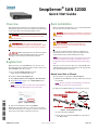
1
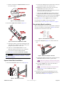
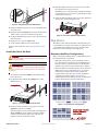
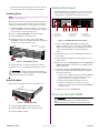
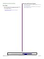
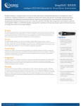
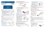
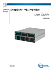
SnapServer® SAN S2000 Quick Start Guide Overview Rack Installation This document describes how to unpack an SnapServer SAN S2000 appliance from Overland Storage and install it into a four-post, 32-inch depth, EIA-310 rack. WARNING: To reduce the risk of electric shock or damage to equipment, always remove any power cords while working with the unit. AVERTISSEMENT: pour réduire le risque de choc électrique ou endommagement de l'équipement, retirez toujours les cordons électriques en travaillant avec l'appareil. CAUTION: While working with the unit, observe standard Electrostatic Discharge (ESD) precautions to prevent damage to micro-circuitry or static-sensitive devices. Register First Before starting, it is essential that you activate your Overland warranty. Technical and warranty support are not available until this is done: 1. Go to the Overland Storage web site (http://www.overlandstorage.com/). Before installing the disk drives, it is recommended that the unit first be secured in the rack. WARNING: Use care during rack installation or removal to prevent accidental tipping of the rack causing damage or personal injury. AVERTISSEMENT: soyez prudent lors de l'installation ou de l'enlèvement du support afin d'empêcher le renversement accidentel de la crémaillère, pour éviter dommages et blessures. The rail kit included with the S2000 is adaptable for installation in the two major types of hardware racks: squared-holed and round-holed EIA-310 racks. NOTE: A two-post telco-style rack or any rack that is less than 29-inches in depth will not support this appliance. Also, for threaded-hole racks, Overland Storage recommends using a shelf. The rails are not universal. They are stamped LH (left) and RH (right) and must be mounted on the appropriate side (when facing the rack front). Attach Inner Rails to Chassis 2. Click the Service & Support tab. This procedure is required for all rack types: 3. Select My Products tab > Register New Product. 1. Mark the screw holes on the rack where the rails will be installed. 4. At the Site Login, enter your e-mail address and password (Figure 1). NOTE: If you are not yet a member, click “New member?” and follow the instructions given. It’s free and easy! NOTE: Be sure rear holes are horizontally in line with the front holes to ensure the unit remains level. 2. Remove the inner rail (Figure 2) from the rail set: Inner Member Latch *10400276003* Middle Member Latch (Hidden) Figure 1. Support Site Login 5. Fill in the information and click Submit. Within three business days, you will receive an e-mail from Overland with your warranty certificate. Follow the instructions included to complete the process. Outer Member Middle Member Figure 2. Inner Rail Release Latch a. Fully extend the rail set. b. Push the inner member latch down, and remove the inner rail. 10400276-003 06/2010 ©2010 Overland Storage, Inc. Page 1 of 6 c. Release and slide the middle member back into the outer member. a. Position the rail against the inside of the rack front rail with the hooks in line with the holes. b. Insert the bracket front into the rack rail and press down so that the hooks catch. Middle Member Latch The spring-loaded tabs will extend into the hole to prevent the rail from unhooking. Outer Member c. Slide the rear segment of the bracket rearward until the hooks are in line with the correct holes. d. Insert the bracket rear into the rack rail and press down so that the hooks catch and the tabs lock. 2. Repeat Step 1 for the right slide rail assembly. Middle Member 3. Verify that the rails are level and straight. Figure 3. Inner Rail Release Latch Continue with “Install the Unit in the Rack” on page 3. 3. Attach the right inner member (Figure 4): Round-Holed Rack Installation Before installing the rails onto a unthreaded round-holed rack, the round-hole rail kit adaptors (Figure 6) must be installed on the ends of the outer rails. A (Front) Align Rear Holes to Tabs B (Rear) Figure 6. Round-Holed Rack Adaptors Screw 1. Attach the adaptors (Figure 7) to both ends of the rail: Figure 4. Attach Inner Rail Member to E2000 a. Facing the chassis, position the rail against the right side of the appliance with the locking tabs going through the holes on the rail. Adaptor “A” Stamp b. Slide the rail toward the front to lock it. This may require some force as it is a tight fit. c. Secure the rail with its Phillips screw. 4. Repeat Step 3 to install the left inner member. IMPORTANT: Depending on your rack type, continue with either the “Square-Holed Rack Installation” or “RoundHoled Rack Installation.” Figure 7. Attach the Adaptor to the Front a. Position the adaptor stamped “A” at the front of the left outer rail (end with the graphic label). Square-Holed Rack Installation NOTE: Make sure the stamp is at the top and the square adaptor holes are aligned with the hooks on the outer rail. 1. Attach the left outer rail to the rack (Figure 5): b. Press the adaptor onto the hooks and slide it upwards until it locks (clicks). Tab NOTE: The rail buttons will snap into the square holes. c. Repeat Steps a–b for the left rear adaptor (stamped “B”). 2. Facing the rack, position the left rail in the rack, aligning the adaptor holes with the front left rack holes being used (Figure 8 on page 3). Hooks Figure 5. Attaching Front of Rail 10400276-003 06/2010 ©2010 Overland Storage, Inc. Page 2 of 6 4. Slide the unit in and out a few times to ensure that the expansion array does not bind. If binding occurs, verify that the front and rear flanges are mounted in the correct holes, readjusting the slide positioning as necessary. 5. Using the two screws provided, secure the expansion array flanges to the rack (Figure 10). Figure 8. Using the Early Round-Hole Adaptors 3. Using the screws from the kit, secure the front of the rail to the rack. 4. Slide the rear rail segment rearward until the rear adaptor holes are in line with holes being used. 5. Using the screws from the kit, secure the rear of the rail to the rack. 6. Repeat Steps 1–5 for the right rail. 7. Verify that the rails are level and straight. Continue the installation with “Install the Unit in the Rack.” Install the Unit in the Rack Figure 10. Secure the Expansion Array to Rack Disk Drives The S2000 comes without disk drives installed (they are sold separately in singles and 4-packs). A combination of 4 to 12 SAS and/or SATA drives can be installed with blank drive carriers filling in the empty slots. Recommended Drive Configurations WARNING: It is recommended that a mechanical lifter (or at least two people) be used during rack installation or removal to prevent injury. AVERTISSEMENT: pour éviter toute blessure il est recommande qu'un monte-charge (ou deux personnes au moins) soit utilisé lors de l'installation ou de l'enlèvement du support. 1. At the front, extend the middle rail members until they lock (click). 2. Confirm that the ball-bearing shuttles are at the front (Figure 9). Before installing or adding drives to a SAN S2000 server, the following must be observed: • Different capacity drives can be installed; however, they should not be included in the same RAID array, because capacity usage for all drives in the RAID is limited to the capacity of the smallest drive member. • Drives of different rotational speed (such as, SAS and SATA drives) can be installed (Figure 11), but they should not be installed in the same column or be separated from each other by a column of different rotational speed drives (Figure 12). If you are combining drives with different speeds, use the figures below to plan where to place the disk drives. Bearing Shuttle Rotational Speed X Rotational Speed Y Figure 9. Inserting Expansion Array Into Rack Figure 11. Supported Drive Configurations 3. Using a mechanical lifter or two people, insert the appliance into the rack rails. Lift the appliance to its install height and engage the inner members on the appliance with the middle members protruding from the rack, and slide the appliance into the rack until it stops. Do not include drives with different RPMs in the same column. Drive Blanks Figure 12. Unsupported Drive Configurations 10400276-003 06/2010 ©2010 Overland Storage, Inc. Page 3 of 6 • Overland recommends grouping columns of drives of the same speed next to each other when possible. Cable Attachment All cabling and power connections are located on the rear panel of the SAN S2000 appliance (Figure 15). All unit cooling exhaust is handled through the rear panel. Installing Drives NOTE: Do not remove the disk drives from their carriers. Doing so voids the drive warranty. Once the unit is in the rack, install the drives. Initially, the top row is empty and the other two rows are filled with drive blanks. Remove as many blanks as needed: 1. If a drive blank is in the slot where you are about to install a disk drive, remove the blank by pressing the lever release button and pulling it out. 2. Remove a drive assembly from the packaging. 3. Press the button to release the lever. 4. With the button on the right, position the drive assembly in front of the appropriate bay and slide it in (Figure 13) until resistance is felt. 1 2 3 1 - AC Power 2 - Mouse Port 3 - Keyboard Port 4 5 6 7 8 4 - Dual USB Ports 5 - COM Port 6 - Video Port 9 7 - Data Port 1 8 - Data Port 2 9 - Active SAS Port Figure 15. SAN S2000 Rear Panel Connections 1. Plug the network connection into Data Port 1. Using a Category 5e (or better) cable, connect Data Port 1 on the appliance to a Gigabit Ethernet switch on the same LAN segment as the management system. 2. Attach the power cords to the AC Power sockets on back panel. 3. Plug the power cords into an UPS appliance or AC power source. Figure 13. Inserting Drive Carriers 5. Push the lever in to lock the assembly in the bay. 6. Repeat Steps 1–5 for each remaining drive carriers. IMPORTANT: To maintain proper airflow and cooling, a drive assembly or a blank drive carrier must be installed in every slot. No empty slots are allowed. Attach the Bezel Once in the rack, attach the front bezel (Figure 14): 4. Make sure that a iSCSI Initiator and the .NET (dot NET) framework is installed on each Windows host before continuing. 5. Install the Windows SAN Manager Suite software from the supplied CD on a host computer attached to the same subnetwork. • If Autorun is enabled, program launches an HTML contents page where you select the appropriate type of software to load (32-bit or 64-bit). • If you are using a Mozilla-based browser or Autorun is disabled, you need to use your file manager to browse the CD and launch start.html at the root level. 6. Follow the on-screen instructions. Power Up the SAN S2000 1 2 Figure 14. Attaching the Bezel IMPORTANT: Always turn on any EXP E2000 expansion units on before powering up your SAN S2000. This enables the head unit to discover the attached expansions. 1. Insert the bezel tabs into the flange holes. 2. Push the other side in until it latches (clicks). 3. If desired, lock the bezel. 10400276-003 06/2010 ©2010 Overland Storage, Inc. Page 4 of 6 To turn the appliance ON, press and hold the Power button (Figure 16) for no more than one (1) second to begin the power-up sequence. f. At the Summary page, click Close to accept your settings. When the wizard finishes, the Windows SAN Manager Home screen is displayed. Configuration Information Power Button At this point, your SAN S2000 is ready to be configured for your specific environment and needs. The Windows SAN Manager software provides easy access to the Overland storage systems on the network. You can also use the built-in SAN Web Manager to configure a specific appliance, even from a non-Windows system. Reset Access Power HDD NIC 2 NIC 1 Power Fail Overheat /Fan Fail Figure 16. Front Panel Controls and Indicators After you turn the power ON, the System performs a selftest process, which takes a few minutes. You must leave the appliance ON while completing any configuration processes for your application and backup media servers. 1. At the host computer, launch the Windows SAN Manager by selecting Windows Start > All Programs > SnapServer SAN > SnapServer SAN Manager. Automatically, Windows SAN Manager attempts to discover any new SAN S2000 appliances connected to the subnetwork and tries to connect to them. 2. If successful, Windows SAN Manager then opens the SAN Appliance Setup Wizard to guide you through the following setup process: Launching the SAN Web Manager 1. From a Web browser, enter the applicable IP address to access the SAN S2000. 2. Use the following default login (case-sensitive): User Name: admin Password: password (or new assigned password) The Web GUI appears. 3. Continue with the configuration process. Check for Software Updates The latest release of the SAN S2000 software can be obtained from the Overland Storage FTP site: 1. Point your browser to ftp://ftp.overlandstorage.com/Software/Snap. 2. Open the appropriate version folder. a. At the Before You Begin page, click Next. 3. Download the latest software file based on the date. b. At the Licensing Agreement page, read the terms, click the check box to indicate you accept the terms, and then click Next. For additional assistance, search at http://support.overlandstorage.com/. c. At the Identity page, enter a new name if you want to rename the appliance, and click Next. NOTE: We highly recommend changing the name to help identify the appliance on the network. The name must start with a letter; subsequent characters may be letters, numbers or hyphens. Try to keep the name short. Special Notes • The alarm mute and disable buttons can be found in different places: • In the Windows SAN Manager, they are found in the tasks list under Manage SnapServer SAN Pool. d. At the Password page, you must enter a password for the appliance, confirm it, and click Next. • In the SAN Web Manager, they are found by clicking the subsystem name (link) under Pools. IMPORTANT: Overland recommends using a password of at least six alphanumeric characters. • To help identify a disk drive that is currently allocated as a Hot Spare, the red LED blinks on the front of its drive carrier. This blinking action also denotes that the Hot Spare is active and healthy. e. At the Pool Creation page, select the type of policy you want, and click Next. See the user guide for complete details. NOTE: Select the Don’t Create Pool option if you want to create multiple pools or to create a pool using only selected disks in the enclosure. Later, use Windows SAN Manager to create the desired pools. 10400276-003 06/2010 • If your OS supports MPIO, you must install and enable MPIO with your iSCSI initiator. • Replication and Mirroring are optional features that require additional licenses to activate. ©2010 Overland Storage, Inc. Page 5 of 6 Additional Information Warranty and Technical Support For warranty and technical support information, see our Contact Us web page. User Guide For detailed information on configuring your SAN S2000, refer to the SnapServer SAN S2000 User Guide. To search for more service information, visit our Expert Knowledge Base System. It is available online at: http://support.overlandstorage.com/support/ snapserver-san.htm You can get additional technical support on the Internet at http://support.overlandstorage.com, or by contacting Overland Storage using the information found on the Contact Us page on our web site. 10400276-003 06/2010 ©2010 Overland Storage, Inc. Page 6 of 6