1
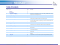
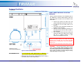
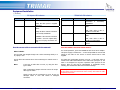
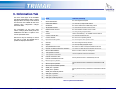
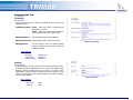
TECHNICAL MANUAL
TRIMAR 802.11a/b/g AP/REPEATER
PEGASUS WIRELESS CORPORATION
TRIMAR TECHNICAL MANUAL
Version 1.0
Introduction
The TRIMAR is a multiple-band, multiple-data-rate, multiple-role wireless
data radio that meets many of the challenges faced by today’s wireless
networking applications.
Compliant with both 802.11b/g and 802.11a standards and operating in
either the 2.4 GHz or 5 GHz bands, TRIMAR offers great flexibility in the
trade-offs between data speed, link distance and frequency planning for
adjacent coverage or linkages.
The TRIMAR can be configured to function as an access point or as a
repeater. Designed for both Indoors and Outdoor uses, it comes with a
weatherproof enclosure and is powered over the Ethernet cable, making
the product extremely easy to install. Its built-in RF connector allows
different types of antennas to be attached, allowing for great flexibility in
terms of deployment coverage and link distance requirements.
Whether used as an access point in a retail hotspot application for
Internet access or as an office wireless LAN (WLAN) for interconnecting
mobile computers, TRIMAR’s multiple SSID and VLAN features provide
service providers and network managers with great versatility in
customizing access control and classes of service for different user groups.
For connecting computer networks in different locations miles apart,
TRIMAR’s capability of working as a repeater, affords network designers,
integrators and contractors great flexibility in constructing point-to-point,
point-to-multiple point, multiple point-to-multiple point networks, as well
as wireless backbones.
The TRIMAR has built-in intelligence capable of automatically forming a
layer-two mesh network and discovering optimal paths. In case of node
failures, it automatically searches out alternative paths, making the
network self-healing and fault tolerant.
Copyright
Information in this document is subject to change without notice. Complying with
all applicable copyright laws is the responsibility of the user. No part of this
document may be reproduced or transmitted in any form or by any means,
electronic or mechanical, for any purpose, without the express written permission of
the seller. If, however, your only means of access is electronic, permission to print
one copy is hereby granted.
The seller provides this documentation without warranty, term, or condition of any
kind. The seller may make improvements or changes in the product(s) and/or the
program(s) described in this documentation at any time.
Other product and company names herein may be trademarks of their respective
owners.
Copyright © 2006, Pegasus Wireless Corporation. All rights reserved.
Notes:
1.
2.
OTC Wireless, Inc. is a wholly owned subsidiary of Pegasus Wireless
Corporation.
The term TRIMAR and TRIMAR AP are used interchangeably throughout
this document.
In addition, the TRIMAR’s ability to support the latest wireless networking
security standards: WPA, WPA2, WEP, AES, TKIP and 802.11i
authentication provides for maximum security deployment options for your
network and securing your data.
PEGASUS WIRELESS CORPORATION
TRIMAR TECHNICAL MANUAL
Version 1.0
Page 1 of 32
Table of Contents
Section
Title
Page
Features
3
Specifications
4
Description
1
Equipment Installation
5
2
Configuring the TRIMAR
9
Basic procedures for working with the TRIMAR web-based administration utility.
3
Information Tab
11
An explanation on how to obtain the current operational status of the TRIMAR.
4
Administration Tab
12
5
Basic Wireless Tab
15
6
Advanced Tab
17
7
SSID Admin Tab
19
8
WEP Security Tab
23
9
Access Control Tab
24
10
WDS Tab
25
11
DHCP Server Tab
27
12
Stations Tab
28
13
Save Tab
29
An explanation on how to create, save and upload a configuration/settings template.
14
Help Tab
31
Where to get Technical support and additional information.
Appendix
PEGASUS WIRELESS CORPORATION
Instructions and considerations for wiring and installing TRIMAR radios including
manufacturer’s recommended practices.
An explanation of the controls for the basic administrative functions of the TRIMAR
including setting a TRIMAR’s IP address or IP addressing mode.
An explanation of the Basic wireless operation controls including controls used to
control the visibility of SSIDs and configuring the controls for channel selection and
turbo mode operations.
An explanation of the Advance wireless operation controls.
An explanation of how to configure the eight SSIDs that a TRIMAR radio can support
including instructions on setting up each SSIDs security policies (WPA/WEP).
An explanation on how to configure the WEP controls.
An explanation of the control that are used to restrict wireless access based on device
MAC addresses.
An explanation on how to set the controls to enable TRIMARs to become participants
in a WDS mesh deployment.
An explanation on setting the controls that will allow the TRIMARs to function as
DHCP servers.
An explanation on viewing information on stations that have associated with the
TRIMAR.
32
TRIMAR TECHNICAL MANUAL
Version 1.0
Page 2 of 32
Features
GENERAL:
Enterprise-class wireless LAN capable of supporting up to 48
infrastructure stations/users.
Power-Over-Ethernet system (POE) allows individual radios to be
powered over the same cable used to carry data.
SSID:
Supports multiple SSIDs. Up to eight simultaneous virtual APs
can be supported by each TRIMAR radio.
Each SSID can have its own individual security and authentication
configuration that supports WEP, WPA or WPA2 (802.11i).
One of the custom configured SSIDs can be selected as the
visible SSID that will be broadcasted in the beacon. The station
users can scan and only see this visible SSID.
The visible SSID can be reserved for guest users. All of the other
SSIDs can be reserved for use by company employees.
TRIMARs can also be configured with none of their SSIDs being
visible.
WIRELESS:
Supports 802.11a and 802.11b/g. A TRIMAR radio can be used in
either 802.11a mode or 802.11b/g mode; but not in both modes
simultaneously.
Supports Atheros SuperA/G turbo mode to boost data rates up to
108Mbps.
Dynamic turbo mode.
Auto-channel setting to allow the radio to select the best channel
automatically during system boot-up.
All APs that are wirelessly linked together need to share the same
channel but can use different SSIDs.
SECURITY:
WPA/WPA2 support for TKIP and AES cipher type with personal
(PSK) and enterprise authentication (through 802.1x with
RADIUS server).
Two RADIUS servers setup per each virtual AP to provide flexible
and redundant deployment.
Supports four WEP keys (64-bits/128-bits) and authentication
type (open / shared key) is shared by each virtual AP and WDS
services.
Individual local bridging enable/disable. When disabled, even
stations assigned with the same SSID cannot communicate with
each other.
WEP key is shared with other virtual APs in the same BSS
network.
NETWORK:
Supports VLAN (Virtual Local Area Network) tags on each virtual
AP. (This function requires a VLAN capable switch or router).
VLAN tagging can be enabled/disabled for each individual SSID.
Each virtual AP can be assigned a unique VLAN ID (1 to 4095).
The VLAN ID determines to which VLAN a station belongs when
the station associated with the SSID.
VLAN support provides more secure network deployment.
Traffic for each individual VLAN ID is separated from each other.
NETWORK MANAGEMENT:
SNMP v1 and v2 with OTC enterprise MIB for total wireless
management.
WIRLESS MESH:
Supports WDS (Wireless Distribution System) with STP (Spanning
Tree Protocol) to link with other APs to form a large wireless
mesh network.
The WDS connection supports unsecured as well as WEP
encrypted deployments.
PEGASUS WIRELESS CORPORATION
TRIMAR TECHNICAL MANUAL
Version 1.0
Page 3 of 32
Specifications
TRIMAR FCC label:
• RF
O
O
O
O
O
O
O
Operating Frequency Range: 2.4 –2.4835 GHz, 5.15 – 5.85 GHz
Data Rate:
54, 48, 36, 24, 18,12, 11, 9, 6, 5.5, 2 and 1 Mbps
Turbo mode:
108 Mbps
Modulation:
OFDM/CCK/DQPSK/DBPSK
Antenna Connector: Type N Female
Transmission Power: 14dBm typical at antenna port
Receiving Sensitivity: 65dBm @ 54 Mbps, -80dBm @11Mbps, at 10-5 BER
• Network Interface: 10/100BaseT RJ-45
Figure 1: TRIMAR FCC label
• Security: WPA, WPA2, WEP, TKIP, AES, 802.11i
This label is located on the back of all official TRIMAR products. The
unit’s unique hardware MAC address and serial number are affixed on
this label.
• Management: WEB, SNMP
Hardware MAC address:
This is separately indicated from within
the TRIMAR’s web-based administration
utility. The hardware MAC address on
the label should match the web-based
administration utility’s reported MAC
address
(unless
this
has
been
subsequently modified by the user).
Product Serial Number:
This number is needed for product
verification should the unit ever require
servicing
by
Pegasus
Wireless
Corporation.
• Environment:
O Operating Temperature: -10o to 65oC
O Operating Humidity: 5% -100%. Rain proof
• Physical Dimension:
O 5.375 inches x 4.75 inches x 2 inches
• Certification: FCC, CE
PEGASUS WIRELESS CORPORATION
TRIMAR TECHNICAL MANUAL
Version 1.0
Page 4 of 32
1. Equipment Installation
Tip:
Manufacturer’s Recommended Practices
Place a UPS battery back-up unit or as a minimum,
a surge protector between the power supply outlet
and AC-DC adapter.
Applying Power and network connections to your TRIMAR Radio
Figure 2: Hooking up the DC-Injector
Safety Statement:
Use only the power adapter provided with this product or other Pegasus
Wireless Corporation authorized replacement power adapter. Connect the
power adapter to a properly grounded electrical outlet that is near the
product and easily accessible.
WARNING: The DC-injector and the power adapter are not
intended for outdoor use. These should be
protected from the elements and damp at all
times.
Refer service or repairs to a professional service person.
PEGASUS WIRELESS CORPORATION
TRIMAR TECHNICAL MANUAL
Version 1.0
Page 5 of 32
Equipment Installation
(.. /continued)
Installing the TRIMAR Radio
HOW TO RESET THE RADIO TO FACTORY
DEFAULTS:
Should it become necessary to do a hardware reset of
the TRIMAR AP to factory default settings, follow the
steps below. Refer to Figure 3 for the location of the
reset button:
1.
2.
3.
4.
5.
Unscrew and remove the cable cover and
gently pull assembly away from the main case.
To reset the unit the radio needs to be
powered.
Press firmly on the reset button and watch the
indication of the LED lamps.
When the reset is successfully performed, the
LED lamps will dim and then light up again as
the unit reboots.
After resetting, reconnect the CAT 5 cable and
replace the cable cover taking care to ensure
that this is replaced correctly to avoid
moisture from getting into the unit.
DO NOT UNDER ANY CIRCUMSTANCE OPEN THE PRIMARY
CASE OF THE RADIO. DOING SO WILL BREAK THE SPECIAL
WEATHER SEAL BETWEEN THE CASE COVER AND MAIN
CASING AND WILL AUTOMATICALLY VOID THE WARRANTY
ON THE UNIT.
THERE ARE NO USER SERVICABLE PARTS INSIDE THE CASE.
Figure 3: Bracket assembly details
RECOMMENDATIONS:
After fixing and testing the radio at its final
WARNING:
location, use the weather sealant provided to protect
the antenna and N-connector from the elements. Failure
to do so could cause water to corrode the connection or allow
water seepage to penetrate the weather casing and causing
catastrophic damage to the radio circuitry.
1. Do not mount the radio upside down or sideways. The
type N-connector must face downwards towards the ground.
2. Strap down the external CAT 5 cable leading from the radio to
the antenna mast or other suitable fixture.
PEGASUS WIRELESS CORPORATION
TRIMAR TECHNICAL MANUAL
Version 1.0
Page 6 of 32
Equipment Installation
(.. /continued)
DC-Injector LED indicators
LED
Power
Color
Amber
Network
Amber
State
OFF when there is no power.
Steady ON when power is supplied
to the unit.
OFF when network connection is
absent.
Steady ON when network connection
is successfully established.
BLINKING if the network connection
is unstable – check or replace cable;
make sure all plug connections are
snug.
Use the correct cable to connect with the network!
Rule of Thumb:
Use the white UTP straight-through CAT-5 when connecting directly to a
PC, laptop or hub.
Use the blue UTP crossover CAT-5 when connecting to a network router or
switch.
Note:
If one type of cable does not work, try using the other
type of cable.
Many contemporary laptops and some routers will accept
either type of cables.
Check to make sure all connections are snug. Do not use
damaged cables or ones with broken or damaged
connectors.
PEGASUS WIRELESS CORPORATION
TRIMAR TECHNICAL MANUAL
TRIMAR-AP LED indicators
LED
NW (network)
Color
Amber
RX
Green
TX
ON
(receive)
(transmit)
(power)
Red
Red
State
Steady ON when network
connection
is
successfully
established.
BLINKING when receiving
data.
OFF when radio is idle or
unable to receive data.
BLINKING when transmitting
data.
OFF when radio is idle or
unable to transmit data.
Steady ON when there is
power.
USE THE CORRECT VOLTAGE POWER SUPPLY.
For normal operations, power the TRIMAR AP with the 9V AC-DC adapter.
This power supply is rated 9V DC ~ 1A and will provided the correct POE
voltage to the radio via the 30-foot or 80-foot external CAT 5 cable
supplied.
For testing and configuration purposes a 5V DC ~ 1.5A power socket is
located on the radio underneath the CAT-5 cable cover (see Figure 3). The
radio is not designed for long-term operations when powered in this
manner. Doing so may lead to unpredictable or undesirable results,
including, but not limited to data loss or hardware damage.
Absolutely DO NOT use the 9V AC-DC adapter to power the radio at the
5V DC socket as this will overload the unit’s circuitry and render the radio
completely inoperative.
Version 1.0
Page 7 of 32
Equipment Installation
Tip:
(.. /continued)
Always test all equipment at the workbench before
installing them at their final positions.
Example Installations
Figure 4: Typical TRIMAR deployment schematic
Figure 5: TRIMAR repeater mode schematic
Figure 4 above illustrates a common wiring scheme for a TRIMAR radio unit
that is physically connected to the network.
Figure 5 illustrates a TRIMAR radio used as a repeater. In this type of
deployment, no physical connection to the network is necessary, all
communications is done via the 802.11 wireless connections.
A set up like this can be used to connect with another TRIMAR radio in a
separate building that is wired similarly to form the basis of a wireless
point-to-point bridge. Alternatively, it can be connected wirelessly with
TRIMAR repeaters (as shown in Figure 5) to form a larger wireless mesh.
In both of these types of operations, the TRIMAR APs need to be
configured to operate in WDS mode.
PEGASUS WIRELESS CORPORATION
TRIMAR TECHNICAL MANUAL
To work in this mode, the TRIMAR radio must be configured using WDS
and connected wirelessly to at least one radio that is physically connected
to the network being serviced.
Version 1.0
Page 8 of 32
2. Configuring the TRIMAR AP
Basic Procedure
The TRIMAR AP uses a web-based administration utility. To access this
utility you will need to use Microsoft ® Internet Explorer, Mozilla Firefox or
a compatible web-browser.
Accessing the web-based administration utility:
1.
2.
3.
Connect a PC either directly to the TRIMAR radio. If the radio is
already configured for operation on an established network,
connect to it via a network route.
The PC connecting with a TRIMAR radio’s web-based
administration utility must be on the same IP subnet as the radio.
(See insets at right).
Enter the IP address of the TRIMAR into the web-browser
window and click “Go”.
Preset Factory Defaults:
IP address:
Subnet Mask:
Default Gateway:
169.254.1.240
255.255.0.0
169.254.1.1
User name:
Password:
admin
public
Using the OTC Device Locator:
Figure 6: Enter the TRIMAR's IP address into the browser's address bar
4.
Enter the correct account and password when security dialog
panel appears.
Figure 8: OTC 802.11g Device Locator GUI
The OTC Device Locator program can be found on the CD that is distributed with
the TRIMAR AP. Install it on to the PC by creating a folder for it and copying the
.exe and .dll file into the new folder.
The Locator will locate all OTC AVCW and TRIMAR radios within the same network.
Its primary use is to identify the IP and MAC addresses of the radios.
Figure 7: Web-based administration password challenge dialog box
PEGASUS WIRELESS CORPORATION
TRIMAR TECHNICAL MANUAL
The PC running the program needs to have a wireless card; be connected to the
same network; or directly with at least one OTC 802.11g radio. To use the
program, simply click the “Scan” button and wait for the program to report its
findings. If the PC and the radio being accessed are already on the same IP subnet,
clicking on the “Web” button will open the default web-browser, which will proceed
to connect directly with the selected product’s web-based administration utility.
Version 1.0
Page 9 of 32
Configuring the TRIMAR AP
(.. /continued)
Navigating and using the web-based administration utility
The different pages of the web-based
administration utility can be accessed by
clicking on the buttons located on the left
side of the web-based administration
screen.
Make all the desired changes under each
tab and “Save” the changes before
moving to the next tab. If the only
changes that are being made are under
the same tab, simply click “Reboot” to
apply the settings. Otherwise, proceed to
other pages to make (and save) other
changes and only reboot the unit after all
configuration tasks have been completed.
SAVE CHANGES
PAGES:
BEFORE
SWITCHING
Figure 11: Reboot the unit to apply changes
If changes are not saved before
switching to another page, the
changes will be lost.
Clicking on the Cancel button will
abandon all changes made and
will reset the fields to their
previous values.
Figure 9: TRIMAR webbased
administration
navigation tabs
REBOOT THE TRIMAR AP
CHANGES HAVE BEEN MADE:
Figure 10: Save changes before changing pages
AFTER
IMPORTANT:
If you change the IP address of the TRIMAR AP, and this puts it on
a different IP subnet from the PC used to configure the settings,
the web-based administration utility may be unreachable until the
PC itself is set to operate within the same IP subnet.
ALL
If the TRIMAR AP is not rebooted
after all changes have been
made, closing the web-based
administration utility will cause all
newly enter custom settings to
be lost.
PEGASUS WIRELESS CORPORATION
TRIMAR TECHNICAL MANUAL
Version 1.0
Page 10 of 32
3. Information Tab
This is the “home page” of the TRIMAR’s
web-based administration utility. It will be
displayed when the utility is first accessed
and whenever the TRIMAR AP has been
rebooted after configuration changes
have been made.
The information on this page gives
various readings polled directly from the
TRIMAR AP. This data is a “capture” of its
current operational status.
Note that it may be necessary to refresh
the page to re-poll the TRIMAR AP to
update the displayed information.
Field
Definition/Meaning
1
Access Point Name:
The units assigned name/label
2
Radio MAC Address:
The units factory assigned MAC address
3
IP address:
The units IP address and IP addressing scheme
4
AP firmware version:
The units software firmware version number
5
Radio firmware version:
The units hardware firmware version number
6
SSID:
The units (primary) assigned SSIDs
7
Cell ID:
Used for load balancing – see TRIMAR Controller Manual
8
Current transmit rate:
The units data transmission rate
9
Current channel:
The unit’s current operating channel
10
Operational radio profile:
The unit’s assigned radio operation mode
11
Security:
The unit’s configured security schemes
12
Region:
The unit’s operating geographic region
13
Associated station count:
The number of radios currently associated with the unit
14
Number of stations allowed to associate:
The number of radios allowed to associate with the unit
15
Ethernet MAC Address:
Same as 2. above unless user reconfigured
16
Total packets received:
17
Total packets transmitted:
18
Packets received to host:
19
Packets transmitted from host:
20
Ethernet port rx packets:
21
Ethernet port tx packets:
Total of all packets received or transmitted
22
Ethernet port broadcast packets:
23
WLAN port rx packets:
24
WLAN port tx packets:
25
WLAN port broadcast packets:
26
WDS port rx packets:
27
WDS port tx packets:
28
WDS port broadcast packets:
Total of packets received or transmitted by the host
Total of packets received, transmitted or broadcasted via LAN
port
Total of packets received, transmitted or broadcasted via WLAN
port
Total of packets received, transmitted or broadcasted via WDS
port
Table 1: System status definitions
PEGASUS WIRELESS CORPORATION
TRIMAR TECHNICAL MANUAL
Version 1.0
Page 11 of 32
4. Administration Tab
Device Control:
(See Figure 12)
Reboot:
Reset Configuration:
Clicking on this button causes the unit to be
rebooted. This is normally used in conjunction
with configuring the TRIMAR AP.
Clicking on this button causes the unit to reboot
and will reset the unit’s configuration back to its
original factory default settings. Use with
caution as this will cause all custom user
settings to be lost.
Figure 12: Device Control
Firmware Upgrade:
(See Figure 13)
These controls are used to upload firmware and patches into the TRIMAR
AP.
Browse:
Use the “Browse” button to select a patch to
upload.
Upload:
Use the “Upload” button to apply a selected
patch to the unit.
Once a patch has been successfully uploaded, the TRIMAR AP will
automatically reboot.
Important:
Figure 13: Firmware Upgrade
Use only official firmware patches supplied by
Pegasus Wireless Corporation or an authorized
dealer/reseller.
Device Name:
(See Figure 14)
This field is used to give a TRIMAR AP a custom label/name to help more
easily identify the unit for administrative purposes. The label will be
displayed in the OTC Device Locator panel together with the unit’s IP
address.
Figure 14: Device Name
The value entered into this field has no other impact on the TRIMAR AP’s
operational characteristics.
PEGASUS WIRELESS CORPORATION
TRIMAR TECHNICAL MANUAL
Version 1.0
Page 12 of 32
Administration Tab
(.. /continued)
IP settings:
(See Figure 15)
These controls are used to assign the TRIMAR AP with its custom IP
addressing scheme.
IP Addressing Mode:
Static – select this control if a static/fixed IP
address is to be used.
DHCP – select this control if the IP address is
to be assigned by an external DHCP server.
Default IP address:
Use this field to enter a valid IP address.
Default subnet mask: Use this field to enter a valid subnet mask.
Default gateway:
Figure 15: IP settings
Use this field to enter the default gateway
(router IP address) for the subnet on which the
TRIMAR is located.
Factory Defaults:
IP address:
Subnet mask:
Default gateway:
169.254.1.240
255.255.0.0
169.254.1.1
Security:
(See Figure 16)
These controls are used to set the account name and password used to
access the web-based administration utility. If these are changed, these
should be properly documented as the only way to re-access a unit’s
administrative controls should the password be lost is to perform a hard
reset on the unit which may be extremely difficult if the radio is located in
a hard to access location.
Figure 16: Security
Factory Defaults:
User name:
Password:
PEGASUS WIRELESS CORPORATION
admin
public
TRIMAR TECHNICAL MANUAL
Version 1.0
Page 13 of 32
Administration Tab
(.. /continued)
SNMP Setting:
(See Figure 17)
These controls are used to enable SNMP control of the TRIMAR AP.
SNMP enabled:
Check this box
management.
to
enable
SNMP
SNMP server IP address:
This field is used to direct the TRIMAR AP
to the network location of the SNMP
server.
Read community:
SNMP read community string
Write community:
SNMP write community string
Figure 17: SNMP Setting
Load Control & Balance Setting:
(See Figure 18)
These controls are normally used to allow managed load-balancing of the
TRIMAR AP and requires the use of the TRIMAR Controller for full
functionality.
Controller IP address:
This field is used to direct the TRIMAR AP
to the network location of the TRIMAR
Controller.
Load Limit:
By default, the TRIMAR AP is factory set
to allow support to a maximum of 48
stations. This can be manually overridden
by entering another value. Restricting the
number of stations that are permitted to
associate with the unit may help improve
service in deployments where a few
specific individual stations demand a large
percentage of the overall available
bandwidth capacity.
If the TRIMAR Controller is used to
control the load-balancing of the TRIMAR
AP, the value entered into this field may
be
superceded
by
administrative
directives.
PEGASUS WIRELESS CORPORATION
TRIMAR TECHNICAL MANUAL
Figure 18: Load Control & Balance Setting
TRIMAR CONTROLLER
The TRIMAR Controller is sold separately and is usually required in
wireless deployments where the load capacity of the TRIMAR wireless
system needs to be managed for optimum network performance.
The use of the TRIMAR Controller allows network managers to fine tune
their systems and provides complete monitoring and administration
functions of the entire TRIMAR system.
Please contact Pegasus Wireless Corporation or authorized dealer/reseller
for additional information on the TRIMAR Controller.
Version 1.0
Page 14 of 32
5. Basic Wireless Tab
(See Figure 19)
Wireless On/Off:
This control allows a TRIMAR AP to be
switched On or Off. This is not the same as an
on/off switch. It simply allows the wireless
functions of the radio to be switched off for
maintenance or other contingencies.
Visible SSID:
The TRIMAR AP can support up to eight SSIDs
simultaneously. Only one can be visible. This
control is used to specify which SSID is to be
made visible. Alternatively, the same control is
used to make all the SSIDs invisible (choose
“None”).
Transmission Rate:
This control allows users to specify a data
transmission rate. It is recommended that this
should be left at the factory preset - Best
(automatic). When turbo modes are enabled,
transmission rates are doubled.
The following controls are inter-related:
802.11 Mode:
This control sets the TRIMAR AP’s 802.11
operation mode. Note that if 802.11a is
selected, an antenna in the 5 GHz range is
required. All other modes require that the
TRIMAR AP be equipped with a 2.4 Ghz
antenna.
Figure 19: Basic wireless controls
Adaptive Radio Selection:
This box is checked by default and this
enables the TRIMAR AP’s Adaptive Radio
feature. This control enables the use of the
TRIMAR’s Super A/G with Dynamic Turbo
mode. It needs to be unchecked if the turbo
mode is disabled or if other turbo modes are
selected.
Super mode:
This control determines which type of turbo
mode the TRIMAR AP will use. See Table 2 for
a full explanation of the choices. Turbo modes
always use preset default channels.
PEGASUS WIRELESS CORPORATION
TRIMAR TECHNICAL MANUAL
Version 1.0
Page 15 of 32
Basic Wireless Tab
(.. /continued)
(See Figure 19 on previous page)
Auto Channel Select:
This control allows the TRIMAR AP to
automatically select what it determines is the
best channel to use. This occurs during the
radio’s boot up process. The channel it selects
can be seen under the Information Tab.
Channel:
This control is used to set a channel manually.
Channels cannot be manually set when Super
modes are enabled or if the radio has been set
to automatically select a channel when it boots
up.
To manually set a channel it is necessary to
uncheck both the Adaptive Radio Selection and
the Auto Channel Select check boxes.
Additionally, the super modes must be
disabled.
PEGASUS WIRELESS CORPORATION
TRIMAR TECHNICAL MANUAL
Super Mode Options
Disabled
Super A/G without Turbo
Super A/G with Static Turbo
Super A/G with Dynamic Turbo
(AR enabled)
This is the Factory default. If in
doubt, leave the TRIMAR AP in
this mode. The cognitive radio
technology will optimize all
wireless operations automatically.
Super mode operation is disabled.
These modes are based on
Atheros A/G cognitive radio
technology.
Requires all WLAN equipment or
computers to be Atheros A/G
enabled for full benefits.
When used with standard WLAN
equipment, there should be at
least a 10%-20% performance
gain, depending on factors
present in the local operational
environment.
Table 2: Super mode options defined
Version 1.0
Page 16 of 32
6. Advanced Tab
(See Figure 20)
Fragmentation Threshold:
This determines the maximum size of
a data package in bytes. Packages larger than
the set value will be broken up for
transmission purposes. Reducing the package
size in a noisy wireless environment should
maintain overall performance.
Factory default:
3200 bytes
RTS/CTS Threshold:
Reducing the preset value will enable
RTS/CTS
and
may
maintain
overall
performance in a noisy wireless environment.
Factory default:
3200 bytes
Beacon Period:
This value determines the number of
milliseconds between AP beacon periods. This
controls the frequency that the AP will
broadcast its presence to other radios on the
network.
Factory default:
100 milliseconds.
Burst Time:
This value controls the number of
microseconds that the radio will occupy its
assigned channel for transmission purposes.
Increasing this value can help increase the
data throughput rate.
Factory default:
0 microseconds (disabled)
Power Saving:
By default, the TRIMAR AP will go into
standby mode if it has been idle for a preset
period. It will fully activate immediately if it
needs to send or receive data.
Factory default:
Enabled
PEGASUS WIRELESS CORPORATION
TRIMAR TECHNICAL MANUAL
Figure 20: Advanced wireless
Version 1.0
Page 17 of 32
Advanced Tab
(.. /continued)
(See on previous page Figure 20)
DTIM Interval:
This value determines the frequency when the
radio will send broadcast/multicast packets to
stations in power save mode. This function is
associated with the Beacon Period.
Factory default:
1 (each beacon period or once every 100
milliseconds)
802.11d
Global Harmonization control.
Factory default:
Disabled.
Transmit Power:
This controls the power output permitted to
the antenna. If the radio is causing
interference to another device, reducing the
antenna’s output may help alleviate the
problem. Do not reduce the power level for
any other reasons.
Factory default:
High
WLAN MAC address:
The MAC address of the wireless port. If left
blank, the factory preset MAC address will be
used. The factory default MAC address is
reported on the Information tab report screen.
Factory default:
blank (hardware MAC address is used)
PEGASUS WIRELESS CORPORATION
Note about the TRIMAR MAC address options:
The TRIMAR AP supports 2 MAC addresses, one used to address the
Ethernet port and the other the Wireless port. By default, these are set to
a particular unit’s hardware and are unique to the unit.
It is possible to manually enter and override the hardware MAC address by
entering the new MAC address information into the following areas:
WLAN MAC address field
Ethernet MAC address field -
TRIMAR TECHNICAL MANUAL
Version 1.0
Advanced Tab
WDS Tab
Page 18 of 32
7. SSID Admin Tab
SSID CONTROLS
(See Figure 21)
SSID #:
Selecting an item in this dropdown menu allows
configuration to be performed on the SSID
selected. All the settings on this page are the
exclusive properties of the selected SSID. Note
the SSID number at the top of the frame – this
indicates exactly which of the eight-supported
SSID is currently being configured.
The TRIMAR AP is designed to be able to support up to 8 SSIDs
simultaneously. Each SSID can be assigned unique security policies and
can individually be assigned to a separate VLAN. Only one SSID can be
made visible; the other seven will be invisible. The TRIMAR AP can also
be configured so that none of the SSIDs is visible. All created SSIDs will
share the same WEP keys (for those SSIDs configured to use WEP) as
well as the same channel assignment as set under the Basic Wireless
Tab. Additionally, the total number of stations that the TRIMAR AP can
simultaneously support remains at 48 stations over all created SSIDs.
Enable this SSID:
Check this box to enable the selected SSID.
Factory default:
Only SSID 1 is enabled by default.
Wireless Network:
Name (SSID)
Enter the desired SSID into this field.
(up to 32 characters)
Factory default:
TRIMAR
Disable Local:
By default, all stations connected to the TRIMAR
AP
are able to see and communicate with each other.
Checking this box will stop associated stations
from being able to see each other.
Bridging
Figure 21: SSID controls
This is useful for SSIDs that are used to service
“hot-spots” or “Guests accounts”. In these types
of deployments, it may not be desirable for PCs
connected to the same TRIMAR AP to be aware of
each others’ presence.
PEGASUS WIRELESS CORPORATION
TRIMAR TECHNICAL MANUAL
Version 1.0
Page 19 of 32
SSID Admin Tab
(.. /continued)
WPA configuration
(See Figure 22)
Each configured SSID can support its own unique WPA configuration,
which it does not need to share with the other SSIDs in the configuration
set.
WPA Enable:
Check this box if WPA is to be used to secure this
SSID’s wireless access and transmissions.
WPA Mode:
Select the desired WPA mode. The following choices
are available under the dropdown menu:
WPA
WPA2
WPA2 only
Cipher Type:
Select between the following:
TKIP
AES
TKIP and AES
PSK:
Enter a valid PSK Pass phrase. Minimum 8
characters to a maximum of 63 characters.
WPA Group Key:
Update Interval
Value in seconds after which the Group Key will be
refreshed.
Factory default:
3600 seconds (one every hour)
Note:
WPA-PSK with a TKIP/AES cipher can use for WPA
security without the presence of an 802.1X
authentication service. With this type of
implementation,
the
associated
radios
will
authenticate amongst themselves.
Figure 22: WPA configuration
WPA and TRIMAR APs in WDS mode
TRIMAR APs deployed in a WDS mesh cannot use WPA. All that is needed
to configure TRIMAR AP to work within a mesh is that the WDS function be
enabled and the MAC addresses of the other units in the same WDS mesh
be made known to all radios operating within the same mesh.
SSIDs serves no function in a TRIMAR AP WDS deployment. This means
that the individual TRIMAR APs within the WDS mesh can still use WPA
security policies associated with the individual SSIDs. These SSIDs can be
used with station units that are not immediate members of the WDS mesh.
TRIMAR APs set up as repeaters without a direct Ethernet connection with
the network should not use WPA with an 802.1X authentication service.
This type of WPA implementation is ideal for static
wireless deployment such as point-to-point,
building-to-building wireless bridges as they offer
maximum wireless security without the cost and
complexity associated with setting up a full 802.1X
authentication service.
PEGASUS WIRELESS CORPORATION
TRIMAR TECHNICAL MANUAL
Version 1.0
Page 20 of 32
SSID Admin Tab
(.. /continued)
802.1X configuration
(See Figure 23)
If WPA is used in conjunction with a RADIUS Server, these controls are
used to activate this service. The TRIMAR AP can support two RADIUS
servers. The first RADIUS server entered is the “preferred” server, and
the second RADIUS server entered is the “backup” server that will be
accessed if, for whatever reason, the first server cannot be located.
Authentication Timeout:
By default the 802.1X service will reauthenticate an associated station
once every 60 minutes.
RADIUS Server IP address:
The IP address of the Radius Server.
RADIUS Server Port number:
The port used by the 802.1X service.
RADIUS Server shared secret:
For enhanced security purposes the
shared secret password should not
be a word found in a dictionary and
be at least 16 characters long.
MAC Address Authentication:
Check this box if the 802.1X
authentication service requires MAC
address verification of associating
stations.
PEGASUS WIRELESS CORPORATION
TRIMAR TECHNICAL MANUAL
Figure 23: 802.1X configuration
Version 1.0
Page 21 of 32
SSID Admin Tab
(.. /continued)
WEP configuration
(See Figure 24)
The same WEP keys are used by all SSIDs using WEP encryption on the
TRIMAR AP. TRIMAR APs deployed in WDS mode are limited to using
WEP.
Enable WEP:
Check this box if the selected SSID
will implement WEP as a component
of its security policy.
Figure 24: WEP configuration
VLAN configuration
(See Figure 25)
Each of the TRIMAR AP’s eight SSIDs can support a separate VLAN.
Enable VLAN for:
This SSID
Check this box if the selected SSID is
a component of a specific VLAN.
VLAN tag:
Enter the correct VLAN tag number.
PEGASUS WIRELESS CORPORATION
TRIMAR TECHNICAL MANUAL
Figure 25: VLAN configuration
Version 1.0
Page 22 of 32
8. WEP Security Tab
WEP configuration
(See Figure 26)
The WEP settings configured under this tab are shared by all SSIDs
configured to use WEP. TRIMAR APs used in WDS mode are limited to
using WEP encryption only.
Enable WEP:
Check this box to enable WEP. Each
SSID using WEP must also have its
WEP configuration box checked.
Default WEP Key:
Select the default WEP transmission
key (1-4). The radio will use this key
for transmissions only. It will be able
to receive data encrypted using the
other three keys.
Authentication:
Open and Shared authentication is
supported.
Factory default:
Open
WEP key length:
Both 64-bit and 128-bit key lengths
are supported.
WEP key 1-4:
Enter the WEP keys using hexadecimal
characters. (1-9 and A-F)
WEP pass phrase generator
Figure 26: WEP configuration
This is a feature and should not be confused with a standard pass phase
field entry. To use this feature enter the desired pass phase into the pass
phrase field. Click on the “Generate WEP keys” function and all 4 keys will
be automatically generated and populate the WEP key fields above.
The generated WEP keys are not viewable. To use corresponding keys to
allow other TRIMAR radios to authenticate, use the exact same pass
phrase in their respective pass phrase generators.
Warning:
Other pass phrase generators may not be compatible
with the TRIMAR WEP key generator.
PEGASUS WIRELESS CORPORATION
TRIMAR TECHNICAL MANUAL
Version 1.0
Page 23 of 32
9. Access Control Tab
Access Control
(See Figure 27)
These controls allow administrators to specifically allow stations to
associate with the access point. This is accomplished by entering the
allowed stations’ unique MAC addresses into the MAC address fields.
Stations whose MAC addresses are not entered into the list will not be
able to authenticate with the TRIMAR AP.
Access Control is also commonly referred to as MAC address filtering.
Enable access control: Check this box if Access Controls are to be
used.
MAC address 1-48:
48 MAC address fields are available, one slot
for each of the 48 stations that the TRIMAR AP
can simultaneously support.
The MAC address needs to be entered as
hexadecimal numbers without delimiters. (A
valid MAC address entry has 12 characters).
Example:
0011F5910E06
Figure 27: Access Control
PEGASUS WIRELESS CORPORATION
TRIMAR TECHNICAL MANUAL
Version 1.0
Page 24 of 32
10. WDS Tab
For load-balance management and other network administrative
functions, use a TRIMAR Controller to manage all aspects of a
TRIMAR WDS mesh.
Wireless Distribution System
(See Figure 28)
WDS is one of the most important TRIMAR AP features. It allows TRIMAR
APs to communicate with each other as well as other makes of APs to
create radial and linear wireless meshes. Each TRIMAR AP can be linked
with up to six other WDS capable APs. This combination can be the basic
component of much larger mesh networks as meshes can easily be linked
with other meshes.
TRIMARs APs in WDS mode must be on the same channel, but
they can use completely separate SSIDs.
Enable WDS:
Check this box to enable the TRIMAR AP’s
WDS feature.
AP MAC address 1-6:
Enter the MAC addresses in hexadecimal
characters of all other APs that will be a part
of the same mesh.
Enable STP:
The Spanning Tree Protocol (STP) must be
enabled for all TRIMAR APs that have a
physical (Ethernet) connection as well as a
wireless connection with the same network.
This will prevent network loops from
occurring due to the multiple paths to the
same network.
Enable WEP for WDS:
Check this box to enable WEP encryption to
be used. The WEP keys need to be entered
under the WEP Security Tab.
Use separate MAC:
For administrative purposes it may be
desirable to manually assign the Ethernet port
a different MAC address. Check this box to
enable this feature.
Ethernet MAC address:
Enter in hexadecimal characters a new MAC
address for the Ethernet port.
WDS table:
This button is used to access the WDS table.
WDS must be enabled to use this feature.
PEGASUS WIRELESS CORPORATION
TRIMAR TECHNICAL MANUAL
Figure 28: WDS configuration
Version 1.0
Page 25 of 32
WDS Tab
(.. /continued)
WDS neighbor table
(See Figure 29)
This display reports on the radios that are a part of the same mesh and
includes information such as the associating units MAC address, SSID and
the wireless signal quality.
WDS table:
This button refreshes the display.
Figure 29: WDS Table
PEGASUS WIRELESS CORPORATION
TRIMAR TECHNICAL MANUAL
Version 1.0
Page 26 of 32
11. DHCP Server Tab
DHCP Server Configuration
(See Figure 30 and Figure 31)
The TRIMAR AP can be configured to function as a DHCP server. To use
this feature, since the TRIMAR AP can only issue IP addresses within its
own IP subnet, the TRIMAR AP must be given an IP address in the
same IP subnet as the IP addresses it will be assigning.
DHCP server:
Check this box to enable the TRIMAR AP’s
DHCP functions.
DHCP address range start: Enter the first number of the fourth octet
in the range of IP addresses to be
assigned.
DHCP address range end:
Enter the last number of the fourth octet
in the range of IP addresses to be
assigned.
DHCP timeout:
Enter the number of minutes that an
issued IP address will remain valid.
Preferred DNS server:
IP address of the primary DNS server.
Alternate DNS server:
IP address of the alternate DNS server.
WLAN client only:
Optionally, the TRIMAR AP can be
instructed to offer IP addresses only to
wireless clients. Check this box to enable
this feature. This function may be
mandatory in some network situations.
DHCP table:
On this tab, use this button to access the
DHCP server client table (Figure 30).
Figure 30: DHCP Server Configuration
DHCP server client table
This report shows information as to which PCs have been assigned DHCP
IP addresses by the TRIMAR AP.
DHCP table:
PEGASUS WIRELESS CORPORATION
On this tab, use this button to refresh the
DHCP server client table (Figure 31).
TRIMAR TECHNICAL MANUAL
Figure 31: DHCP server client table
Version 1.0
Page 27 of 32
12. Stations Tab
Stations
(See Figure 32)
The stations tab display shows information about all stations that have
associated with the TRIMAR AP. Information polled from the associated
stations include the individual stations’ MAC addresses as well as the
number of packets sent and received.
Figure 32: Associated stations display
PEGASUS WIRELESS CORPORATION
TRIMAR TECHNICAL MANUAL
Version 1.0
Page 28 of 32
13. Save Tab
Save Configuration
(See Figure 33, Figure 34 and Figure 35)
A TRIMAR AP’s configuration can be saved to a template and reapplied to
other TRIMAR APs. This feature makes it easy to configure and deploy
multiple units quickly and without having to re-type the configuration
information into every unit. In most instances, all that needs to be
changed are the individual unit’s IP addresses and adjustments to the
WDS settings so that units do not refer to themselves.
Before creating the template, the TRIMAR AP’s IP address needs
to be added to the PC’s Local Intranet zone. (See below for
instructions).
Figure 33: Save Configuration
Create Template: Click on this button to create the template. Another
window will open advising that a wait may be
necessary whilst the computer creates the file. Once
the file is created, a file navigation window will open
allowing an opportunity to choose where to save the
file and renaming it.
Default name is:
settings.htm
TURN OFF THE WEB-BROWSER’S POP-UP BLOCKER OR THE TEMPLATE
FILE WILL NOT BE CREATED
Figure 34: Saving TRIMAR Settings
Assigning the TRIMAR AP to the Local Intranet Zone
1.
2.
3.
4.
5.
6.
7.
8.
Go to the Microsoft® Windows Control Panel.
Find the Internet Options icon and double click to open the
application.
Select the “Security” tab.
Select the Local Intranet icon. The “Sites” button will become
available.
Click on the “Sites” button. In the panel that appears select
“advanced”.
Enter the IP address of the TRIMAR AP, include the “http://”.
(Example: http://169.254.1.240)
Click “Add”. This will add the TRIMAR AP’s IP address to the list.
Click the “OK” buttons to close all the windows.
Figure 35: Save the template file
PEGASUS WIRELESS CORPORATION
TRIMAR TECHNICAL MANUAL
Version 1.0
Page 29 of 32
Save Tab
(.. /continued)
Uploading a template
(See Figure 36)
To upload a template file into a TRIMAR AP open the settings.htm file
using a web-browser.
Target AP:
Enter the IP address of the TRIMAR AP to which the
template is to be applied.
Upload Settings:
Click on this button to upload the template file. This
can take several minutes.
Once the template has fully uploaded, the webbased administration utility for the target TRIMAR
AP will be automatically started. Negotiate the
password challenge screen when it appears. Wait
until the progress bar stops, then reboot the
TRIMAR AP so that the uploaded configurations can
be applied.
Once it restarts, review the uploaded configurations.
In particular, there may be some fields that needs to
be altered (such as its IP address or custom MAC
address settings).
TURN OFF THE WEB-BROWSER’S POP-UP BLOCKER OR THE TEMPLATE
FILE WILL NOT BE UPLOADED
Note:
In particular, be aware that the template is an exact
copy of the settings of the TRIMAR AP on which the
template was created. If this unit has a static IP
address, all subsequent TRIMAR APs to which the
template has been applied will be given the same
identical IP address.
PEGASUS WIRELESS CORPORATION
TRIMAR TECHNICAL MANUAL
Figure 36: Uploading a template
Version 1.0
Page 30 of 32
14. Help Tab
Contact our Technical Support department for additional technical
assistance for configuring and deploying your TRIMAR AP.
OTC Wireless Technical Support Department can be contacted by either
email, phone or the web-mail form on the Pegasus Wireless Corporation
web site:
Email:
Website:
Phone:
Fax:
[email protected]
http://www.otcwireless.com/support/technicalsupport.html
(510) 490-8288 ext 244
(510) 440-7046
Figure 37: Help
PEGASUS WIRELESS CORPORATION
TRIMAR TECHNICAL MANUAL
Version 1.0
Page 31 of 32
Appendix
Limited Warranty
FCC Rules and Regulations - Part 15
The seller warrants to the end user (“Customer”) that this product will be free from
defects in workmanship and materials, under normal use and service, for one (1)
year from the date of purchase. The seller’s sole obligation under this express
warranty shall be, at the seller’s option and expense, to repair the defective product
or part, deliver to Customer an equivalent product or part to replace the defective
item.
This equipment has been tested and found to comply with the limits for a Class B
digital device, pursuant to Part 15 of the FCC Rules. Operation is subject to the
following two conditions: (1) this device may not cause harmful interference, and (2)
this device must accept any interference received, including interference that may
cause undesired operation.
All returns must be authorized by Pegasus Wireless Corporation and accompanied
by a Return Materials Authorization (RMA).
All products that are replaced will become the property of the seller. Replacement
products may be new or reconditioned.
These limits are designed to provide reasonable protection against harmful interference
in a residential installation. This equipment generates, uses and can radiate radio
frequency energy and, if not installed and used in accordance with the instructions,
may cause harmful interference to radio communications. However, there is no
guarantee that interference will not occur in a particular installation. If this equipment
does cause harmful interference to radio or television reception, which can be
determined by unplugging the equipment and then plugging it back in, the user is
encouraged to try to correct the interference by one or more of the following
measures:
•
•
•
•
Reorient or relocate the receiving antenna.
Increase the separation between the equipment and receiver.
Connect the equipment into an outlet on a circuit different from that to which the
receiver is connected.
Consult the dealer or an experienced radio/TV technician for help.
Caution: Changes or modifications not expressly approved by OTC Wireless could void
the user's authority to operate the equipment. This transmitter must not be co-located
or operating in conjunction with any other antenna or transmitter.
FCC Compliance Information Statement
FCC Part 15 Declaration of Conformity (DoC)
The following equipment:
Product Name:
TRIMAR 802.11 a/b/g Wireless AP/BRIDGE/REPEATER
Model Number:
TRIMAR is herewith confirmed to comply with the requirements
of FCC Part 15 rules. The operation is subject to the following two conditions:
Exposure to Radio Frequency Radiation
Caution: The radiated output power of this device is far below the FCC radio
frequency exposure limits. In order to avoid the possibility of exceeding the
FCC radio frequency exposure limits, a minimum separation of 20 cm (8
inches) is recommended between the antenna and any persons.
1. This device may not cause harmful interference, and
2. This device must accept any interference received, including interference that may
cause undesired operation.
FCC ID: MKZTRIMAR
A declaration of conformity with the requirements of the directives is available from:
Pegasus Wireless Corporation, 48499 Milmont Drive, Fremont, California 94538, USA
PEGASUS WIRELESS CORPORATION
TRIMAR TECHNICAL MANUAL
Version 1.0
Page 32 of 32