1
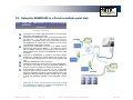
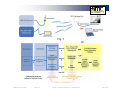
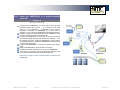
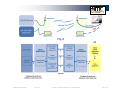
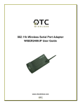
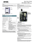
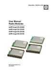
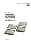
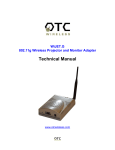
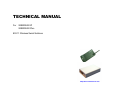
TECHNICAL MANUAL For WiSER2400.IP WiSER2400.Plus 802.11 Wireless Serial Solutions http://www.otcwireless.com Technical Manual For WiSER2400.IP WiSER2400.Plus 802.11 Wireless Serial Solutions Copyright Information in this document is subject to change without notice. Complying with all applicable copyright laws is the responsibility of the user. No part of this document may be reproduced or transmitted in any form or by any means, electronic or mechanical, for any purpose, without the express written permission of the seller. If, however, your only means of access is electronic, permission to print one copy is hereby granted. The seller provides this documentation without warranty, term, or condition of any kind. The seller may make improvements or changes in the product(s) and/or the program(s) described in this documentation at any time. Other product and company names herein may be trademarks of their respective owners. Copyright © 2001-2005, OTC Wireless, Inc. All rights reserved. Version 2.16 WiSER 2400 Technical Manual Version 2.16 Copyright 2001-2005, OTC Wireless, Inc. All Rights Reserved Page 2 of 32 TABLE OF CONTENTS INTRODUCTION 4 1. Installation 6 1.2 Installation of WiSER2400 Administrative Software 9 1.3 Installation of VirCOM, the virtual serial COM port redirector 9 2. WiSER Deployment Strategies 10 2.1 Using the WiSER2400 in a Point-to-point Link 10 2.2 Using the WiSER2400 in a Point-to-multiple point Link 14 Using the WiSER 2400 Administration Software 18 3.1 Overview 18 3.2 Password Protection 20 3.3 Link Status 21 3.4 Configuration Page 22 3.5 Encryption 27 3.6 Statistics 28 3.7 Admin 29 3. APPENDIX 30 Troubleshooting 30 Limited Warranty 31 Regulatory Compliance 32 WiSER 2400 Technical Manual Version 2.16 Copyright 2001-2005, OTC Wireless, Inc. All Rights Reserved Page 3 of 32 INTRODUCTION The WiSER2400.IP and the WiSER2400.Plus are IEEE 802.11b compliant devices with built-in serial interfaces. They are designed to allow nonwirelessly enabled serial devices to be connected and fully integrated into an 802.11 Network. The WiSER2400 receives data from equipment with serial ports; converts the serial data into 802.11 compliant TCP or UDP data packets and transmits these packets wirelessly. Conversely, the WiSER can receive wireless packets, which it unpacks and delivers byte-by-byte to the destination equipment/device through a serial port. The WiSER2400 requires no device driver and is operating system independent. They can be used with almost any type of equipment that uses a serial port, including (but not limited to) cash registers, electronic whiteboards and navigational instruments. Administration of the WiSER2400 is done through a Windows based administrative software program. The administration software can be used to configure the unit’s operating parameters, administrative and local network settings. It can also be used to monitor the unit’s communication link conditions. Fig. 1 WiSER2400.IP The WiSER2400.IP comes with an RS-232 interface and a built-in 2dBi antenna. It comes supplied with a 5V DC power adapter. The WiSER2400.Plus provides the same functionalities as the WiSER2400.IP. It has an RS-232 DB-9 connector as well as a miniPhoenix connector for RS-485/422 interfaces. It accepts 5V DC to 32V DC power supply that has to be provided for separately by the user. Input power connection is made through the mini-Phoenix connector. It also comes with a DIN rail mounting clip and plate assembly. Fig. 2 Note: WiSER2400.Plus Throughout this manual, the term WiSER2400 is used to refer to both the WiSER2400.IP and the WiSER2400.Plus WiSER 2400 Technical Manual Version 2.16 Copyright 2001-2005, OTC Wireless, Inc. All Rights Reserved Page 4 of 32 Key Features Specifications Works with any 802.11b or 802.11g access point Model WiSER2400.IP; WiSER2400.Plus Supports peer-to-peer networking with one another or any 802.11b/g Standard 802.11 and 802.11b station devices Host Interface Supports TCP/IP and UDP networking over 802.11 Frequency RS232 (WiSER2400.IP) RS232/485/422 (WiSER2400.Plus) 2.4GHz – 2.497GHz Plug & Play operation— RF Channels 11 channels (US, Canada), 13 channels (Europe, Japan) Transmission power RF Receiver sensitivity Antenna 16dBm at antenna input typical o o No driver on the host device is required Operation independent of operating system on the host equipment or device (Windows 98/NT/2000/ME/XP, Linux, Unix, embedded, etc.) Supports 64-bit and 128-bit WEP encryption for secured communication 11Mbps data rate and automatic selection of lower data rate (5.5, 2 and 1 Mbps) in degraded RF environment Wireless Data Rate Wireless Modulation Wireless Link Distance Serial interface supports XON/XOFF, DTR/DSR (WiSER2400.IP and WiSER2400.Plus) and RTS/CTS (WiSER2400.Plus) for both local and remote hand-shake/flow control Supports RS-232 interface (WiSER2400.IP) Supports RS-232/485/422 interfaces, selectable by software configuration (WiSER2400.Plus) Compact integrated omni-directional-antenna (WiSER2400.IP) Reverse-SMA RF connector for antenna Input Power Current consumption LED Indicators Microsoft-Windows-based administrative software Protocols supported: TCP, UDP, ICMP, ARP Comes with a virtual serial COM port redirector software, VirCOM Version 2.16 Serial Port Interface Serial Data Rate attachment (WiSER2400.Plus) WiSER 2400 Technical Manual Wireless Network Types Wireless Data Encryption Network Security Operating Temperature Regulation Compliance -80dBm @1e-5 BER typical 2 dBi integrated dipole antenna (WiSER2400.IP); ReverseSMA RF connector (WiSER2400.Plus) 11, 5.5, 2 or 1 Mbps fixed rate, or configured to automatic rate selection CCK, Direct Sequence Spread Spectrum 300 ~1200 ft (WiSER2400.IP, depending on environment); Link Distance for WiSER2400.Plus depends on antenna used Support infrastructure and ad-hoc station modes Support the standard 64-bit and the 128-bit WEP MAC-address-based access control Data Bit: 7/8; Parity: none/even/odd; Stop Bit: 1 1200, 2400, 4800, 9600, 14.4K, 19.2K, 38.4K, 57.6K, 115.2K 5VDC for WiSER2400.IP (adapter provided); 5VDC to 32 VDC for WiSER2400.Plus (to be supplied by user) <480mA (max. reached in transmit-mode) 4: Power, Transmission, Receiving, Link -10°C – 50°C FCC part 15,Class B CE (ETSI EN 300 328-1, ETSI EN 301 489-17) IC Copyright 2001-2005, OTC Wireless, Inc. All Rights Reserved Page 5 of 32 1. Installation 1.1.1 Standard Hardware WiSER2400.IP 1 WiSER2400.IP radio 1 RS232-P cable 1 RS232-C cable 1 ac-dc power adapter 1 pair of Velcro mounting pads 1.1.2 Power WiSER2400.IP Uses 5V DC for input power. adapter is provided. 1.1.3 Serial Connections An AC-to-DC power The RS-232-P cable is for connecting the WiSER2400.IP to the RS232 port of DCE equipment (whiteboard, instrument, etc.) during communication. It terminates in a male DB-9 connector and is labeled “Board” on the cable. The RS-232-C cable is for connecting the WiSER2400.IP to a computer or DTE equipment during configuration using the administrative software. It terminates in a female DB-9 connector and is labeled “Computer” on the cable Version 2.16 WiSER2400.Plus Uses 5V DC to 32V DC for input power (to be supplied by user). See Fig. 4 for an illustration on how to connect the power input to the mini-Phoenix connector. WiSER2400.IP The WiSER2400.IP has a built-in RJ-45 connector and uses an RJ-45 to DB-9 adapter cable for connecting to the serial port of a PC or a device. Two cables are included in the package: WiSER 2400 Technical Manual WiSER2400.Plus 1 WiSER2400.PLUS radio 1 DIN Rail Mounting Assembly WiSER2400.Plus For RS-232 Connection WiSER2400.Plus has a built-in DB-9 connector for RS-232 connection. User is to provide the proper RS232 cable for connection to a PC or a device. Use a null-modem serial cable to connect the WiSER2400.Plus to a PC. Use a straight-thru serial cable to connect the WiSER2400.Plus to a DCE device For RS-485/422 Connection Please refer to Fig. 4 for connecting the RS-485 and RS-422 data lines to the mini-Phoenix connector on the WiSER2400.Plus. Copyright 2001-2005, OTC Wireless, Inc. All Rights Reserved Page 6 of 32 1.1.4 Selecting the Serial Mode for WiSER2400.Plus WiSER2400.IP The WiSER2400.Plus has a 4-position dipswitch next to the mini Phoenix connector for selecting the serial operating mode: RS-232 RS-485 (select RS-485 and half-duplex) RS-422 (select RS-485 and full-duplex) The factory default has the dipswitch set in the RS-232 mode. Please refer to Fig. 4 for details in setting the dipswitch for different operating modes. 1.1.5 Status LEDs Power on the WiSER2400, the LEDs on the front panel should exhibit the following patterns: (Refer to Fig. 3 and Fig. 4) LED Color ON RED RX GREEN Light Blinking Pattern On when transmitting Proper power is supplied Unit is linked to a wireless system Unit is not linked to any wireless system Unit is transmitting RF signal Blinking Serial Mode Steady on Steady on Steady blink TX LINK RED YELLOW Indication Secure the WiSER2400 at the desired location with the provided Velcro (for WiSER2400.IP) or DIN Rail mounting kit (for WiSER2400.Plus) once the hardware is setup and works properly with the intended host device or equipment. WiSER 2400 Technical Manual Version 2.16 Fig. 3 Copyright 2001-2005, OTC Wireless, Inc. All Rights Reserved WiSER2400.IP Page 7 of 32 WiSER2400.Plus This section describes the signals expected on the mini-Phoenix connector pins. 10-pin mini-Phoenix terminal: Dip Switch: Pin: 1. 2. 3. 4. 5. 6. 7. 8. 9. 10. Location (from left to right) DATA+(RS-485) DATA- (RS-485) N/C TX+ (RS-422) TX- (RS-422) RX+ (RS-422) RX- (RS-422) N/C V+ (Up to +32 VDC) GROUND DB 9 male connector: Pin: 1. 2. 3. 4. 5. 6. 7. 8. 9. 1. #RS232/485 selector 2. #Full/Half duplex selector 3. 120 ohm termination -- 422 RX pair 4. 120 ohm termination -- 422 TX pair or 485 pair. For 1 & 2: The level up position is high. The level down position is low. For 3 & 4: DCD RXD TXD DTR Ground DSR RTS CTS - The level up position is without terminator. The level down position is with terminator. Fig. 4 WiSER 2400 Technical Manual Version 2.16 Copyright 2001-2005, OTC Wireless, Inc. All Rights Reserved WiSER2400.Plus Page 8 of 32 1.2 Installation of WiSER2400 Administrative Software 1.3 Installation of VirCOM, the virtual serial COM port redirector 1.2.1 System Requirements 1.3.1 System Requirements To support the WiSER2400 administrative software, the computer must meet the following minimum requirements: To support the WiSER2400 administrative software, the computer must meet the following minimum requirements: Windows®98 (SE)/ NT/ ME/ 2000/ XP One COM port (with a DB-9 male connector or an appropriate adapter to connect to a DB-9 female connector) (Optional) A TCP/IP wireless network that connects the PC running the administrative program and the WiSER2400 unit. Windows®98 (SE)/ NT/ ME/ 2000/ XP Active TCP/IP services VirCOM files are under the VirCOM folder on the distribution CD-ROM. 1.2.2 Installation 1.3.2 Installation To install the administrative program, simply insert the distribution CD-ROM into the CD-ROM drive. Copy the “wauti_nnnn.exe” file to the desired harddrive location on the PC (where ‘nnnn’ is a number). Click on the setup.exe to install VirCOM. WiSER 2400 Technical Manual Version 2.16 See the VirCOM Technical Manual for the detail information on using VirCOM. Copyright 2001-2005, OTC Wireless, Inc. All Rights Reserved Page 9 of 32 2. WiSER Deployment Strategies 2.1 Using the WiSER2400 in a Point-to-point Link 2.1.1 Using the WiSER2400 in a point-to-point link Scheme 1 See Figure 5 (overleaf) Connect the PC to an 802.11b/g access point, or use a PC with a built-in 802.11b/g wireless LAN card. Configure the WiSER2400 to match its serial parameters (baud rate, parity bit, … etc.) with that of the serial device it is to be attached to. Configuration can be done by temporarily connecting the WiSER2400, by a serial cable or wirelessly, to a PC running the WiSER2400 administration software. Configure the WiSER2400 to match up its TCP/UDP/IP settings (listening port, destination IP address, … etc.) with that on the PC side for a TCP/IP or UDP/IP connection. Configure the WiSER2400 to operate in the proper wireless network type: Infrastructure mode for linking to an access point, or Ad-hoc mode for linking with a PC with a built-in wireless LAN card. Attach the WiSER2400 to the serial device. Establish the wireless link between the PC and the WiSER2400. The system is now ready for running the application software on the PC to control the serial device through the wireless link. If the application software on the PC can only communicate through a serial COM port interface and does not support the standard TCP/UDP/IP protocols through the network interface, the COM port re-directing software program, VirCOM, will be needed to bridge the application software to the TCP/UDP/IP network port. Please refer to Section 3 of this manual as well as the VirCOM Technical Manual for details on configuring the WiSER2400 and the Virtual COM port re-directing software. WiSER 2400 Technical Manual Version 2.16 Copyright 2001-2005, OTC Wireless, Inc. All Rights Reserved Page 10 of 32 Fig. 5 WiSER 2400 Technical Manual Version 2.16 Copyright 2001-2005, OTC Wireless, Inc. All Rights Reserved Page 11 of 32 2.1.2 Using the WiSER2400 in a point-to-point link Scheme 2 See Figure 6 (overleaf) Configure the WiSER2400 on the device side to match its serial parameters (baud rate, parity bit, … etc.) with that of the serial device it is to be attached to. Configuration can be done by temporarily connecting the WiSER2400, by a serial cable or wirelessly, to a PC running the WiSER2400 administration software. Similarly, configure the serial parameters of the WiSER2400 on the PC side so that it can communicate with the PC. Configure the WiSER2400s on either side of the link to match up their TCP/UDP/IP settings (listening port, destination IP address, … etc.) for a TCP/IP or UDP/IP connection. Configure the WiSER2400s on both sides to operate in the Ad-hoc mode. Attach the WiSER2400s to the serial device and the PC. Establish the wireless link between the PC and the WiSER2400. The system is now ready for running the application software on the PC to control the serial device through the wireless link. Please refer to Section 3 of this manual for details on configuring the WiSER2400. WiSER 2400 Technical Manual Version 2.16 Copyright 2001-2005, OTC Wireless, Inc. All Rights Reserved Page 12 of 32 Fig. 6 WiSER 2400 Technical Manual Version 2.16 Copyright 2001-2005, OTC Wireless, Inc. All Rights Reserved Page 13 of 32 2.2 Using the WiSER2400 in a Point-to-multiple point Link 2.2.1 Using the WiSER2400 in a point-to-multiple point link Scheme 3 See Figure 7 (overleaf) Connect the PC to an 802.11b/g access point, or use a PC with a built-in 802.11b/g wireless LAN card. Configure each WiSER2400 to match its serial parameters (baud rate, parity bit, … etc.) with that of the serial device it is to be attached to. Configuration can be done by temporarily connecting the WiSER2400, by a serial cable or wirelessly, to a PC running the WiSER2400 administration software. Configure each WiSER2400 to match up its UDP/IP settings (listening port, destination IP address, … etc.) with that on the PC side for a UDP/IP connection. Configure the PC side to operate in UDP broadcast mode. Enable each WiSER2400 to receive UDP broadcasts. Configure the WiSER2400s to operate in the proper wireless network type: Infrastructure mode for linking to an access point, or Ad-hoc mode for linking with a PC with a built-in wireless LAN card. Attach the WiSER2400s to the serial devices. Establish the wireless link between the PC and the WiSER2400s. The system is now ready for running the application software on the PC to control the serial devices through the wireless link. If the application software on the PC can only communicate through a serial COM port interface and does not support the standard TCP/UDP/IP protocols through the network interface, the COM port re-directing software program, VirCOM, will be needed to bridge the application software to the TCP/UDP/IP network port. Please refer to Section 3 of this manual as well as the VirCOM Technical Manual for details on configuring the WiSER2400 and the Virtual COM port re-directing software. WiSER 2400 Technical Manual Version 2.16 Copyright 2001-2005, OTC Wireless, Inc. All Rights Reserved Page 14 of 32 Fig. 7 WiSER 2400 Technical Manual Version 2.16 Copyright 2001-2005, OTC Wireless, Inc. All Rights Reserved Page 15 of 32 2.2.2 Using the WiSER2400 in a point-to-multiple point link Scheme 4 See Figure 8 (overleaf) Configure each WiSER2400 on the device side to match its serial parameters (baud rate, parity bit, … etc.) with that of the serial device it is to be attached to. Configuration can be done by temporarily connecting the WiSER2400, by a serial cable or wirelessly, to a PC running the WiSER2400 administration software. Similarly, configure the serial parameters of the WiSER2400 on the PC side so that it can communicate with the PC. Configure the WiSER2400s on either side of the link to match up their UDP/IP settings (listening port, destination IP address, … etc.) for a UDP/IP connection. Enable the WiSER2400 on the PC side to send UDP broadcasts. Enable each WiSER2400 on the device side to receive UDP broadcasts. Configure the WiSER2400s on both sides to operate in the Ad-hoc mode. Attach the WiSER2400s to the serial device and the PC. Establish the wireless link between the PC and the WiSER2400. The system is now ready for running the application software on the PC to control the serial devices through the wireless link. Please refer to Section 3 of this manual for details on configuring the WiSER2400. WiSER 2400 Technical Manual Version 2.16 Copyright 2001-2005, OTC Wireless, Inc. All Rights Reserved Page 16 of 32 Fig. 8 WiSER 2400 Technical Manual Version 2.16 Copyright 2001-2005, OTC Wireless, Inc. All Rights Reserved Page 17 of 32 3. Using the WiSER 2400 Administration Software 3.1 Overview This chapter describes the functionality and operations of the WiSER2400 Diagnostic and Configuration administrative software program. The WiSER2400 administrative program is supported on Microsoft Windows® 98(SE), NT, Millennium, 2000, and XP. To use the administrative program to monitor and configure the WiSER2400, the PC can be connected to the WiSER2400 either directly through the serial port by cable or via a wireless network connection. A connection selection window will pop up as shown on the right when the administrative program starts. Once the connection selection is chosen, the administrative program will display an interface as shown in Fig. 10 and Fig. 11 respectively, depending on whether the PC is connected to the WiSER2400 by serial port, or by a wireless connection. Fig. 9 WiSER2400 administration connection dialog panel Warning: The administrative program in serial port connection mode will not work if another RS232 application program is set to use the same COM port. Make sure that no other application is connected with the COM port when starting the administrative program. In Windows, any connection with a COM port is exclusive. 3.1.1 The Tabs There are five Tabs in the administrative software interface window: Link Status Configuration Encryption Statistics Administration Each will be covered in detail below. WiSER 2400 Technical Manual Version 2.16 Copyright 2001-2005, OTC Wireless, Inc. All Rights Reserved Page 18 of 32 Fig. 10 Administrative software dialog with a PC connected to the WiSER2400 via a serial cable Fig. 11 Administrative software dialog with a PC connected to the WiSER2400 wirelessly. Fig. 10 shows the administrative program interface when the PC is connected with the WiSER2400 through the serial port by a cable. The user first needs to select the proper COM port on the PC and its baud rate, byte size, and parity (as shown in the top of Fig. 10) to match those of the WiSER2400 before clicking on the “Connect” button to establish communication link between the administrative program and the WiSER2400 unit. Fig. 11 shows the administrative program interface when the PC is wirelessly connected to the WiSER2400. To connect the PC to the WiSER2400 via wireless networking, one needs to make sure that the WiSER2400 and the PC running the administrative software are on the same subnet. Defaults: Baud Rate: 9600 / Data bits: 8 / Parity: none Alternatively, the user can click on the “Detect…” button (as shown in the bottom of Fig. 10) to have the software automatically detect the RS232 parameter settings of the WiSER2400 at a given COM port. The connection between the PC and the WiSER2400 will be automatically made when the administrative software succeeds in correctly detecting the parameter settings of the WiSER2400. Once the connection is made, the Connect button will turn into a Disconnect button. Simply click on the “Disconnect” to terminate the link between the PC and the WiSER2400. WiSER 2400 Technical Manual Version 2.16 The default IP settings for the WiSER2400 are: IP address: Subnet mask: 192.168.11.191 255.255.255.0 The administrative program, when started in the wireless connection mode, will automatically scan for all the available WiSER2400 units on the network. Alternatively, the user can force a scan by clicking the “Get MAC/IP” button as shown in the top of Fig. 4b. The scan results will be displayed in a pull-down list. The user then selects from the menu for the unit to be configured or monitored. Copyright 2001-2005, OTC Wireless, Inc. All Rights Reserved Page 19 of 32 3.2 Password Protection Before any change/modification can be made to the configuration of a WiSER2400, a password must be submitted before the configuration command is executed. After entering the password, click “OK” to proceed “Cancel” to stop. The Password Utility is also used to add or change a password for a WiSER2400 unit. Fig. 12 WiSER2400 Password Utility panel NOTE: The default password of WiSER2400 is none. (Leave the field blank). WiSER 2400 Technical Manual Version 2.16 Copyright 2001-2005, OTC Wireless, Inc. All Rights Reserved Page 20 of 32 3.3 Link Status The Link Status page displays wireless link information such as SSID (of the access point the WiSER2400 is connected with, or the group ID in an ad-hoc peer-to-peer network), the firmware version and release date, role of the radio, RF channel, port status, link quality, and signal strength. Use the Refresh button to retrieve/update the Link Status information. Fig. 13 WiSER2400 administration software Link Status panel WiSER 2400 Technical Manual Version 2.16 Copyright 2001-2005, OTC Wireless, Inc. All Rights Reserved Page 21 of 32 3.4 Configuration Page The Configuration page has four sections: Serial Port Serial IP Proxy Wireless Port Peer Host After selecting the desired section, click on the Refresh button at the bottom of the page to bring up the current settings. After changing the settings, use the Apply button to save the new settings to the WiSER2400. Fig. 14 WiSER2400 administration software Configuration/Serial Port panel WiSER 2400 Technical Manual Version 2.16 Copyright 2001-2005, OTC Wireless, Inc. All Rights Reserved Page 22 of 32 End Frame Byte: 3.4.1 Serial Port (Refer to Fig. 14 on previous page). Serial Parameter Baud rate: This value specifies the character that signals the end of a data-string, and the data would be sent to the destination unit right after the radio receives the designated character. Range 0x00 to 0x1F. Default value: 0x0D = Carriage Return for setting the baud rate of the WiSER2400’s serial port. Supported values: 1200, 2400, 4800, 9600, 14400, 19200, 38400, 57600, and 115200 bps. If the user specifies ‘None’ (or leaves the field blank), this will signify that there is no End Frame Byte and data will be sent immediately once the WiSER2400 receives the next Start Frame Byte. Default value: 9600 bps Parity Bit: for setting the error-checking bit. Supported values: “None”, “Even”, and “Odd” Data Bit: for setting the number of bits in the data section. Supported valued: 7 and 8. Range: 1 to 200 bytes. Stop Bit: supported value: 1. Default value: 200 bytes Flow Control: for setting local flow control option for the serial connection. Supported modes: None, XON/XOFF and Hardware flow control. Serial Interface The WiSER2400.IP supports RS-232 serial interface. The WiSER2400.Plus supports RS-232/485/422 serial interfaces. Data Packetizing Start Frame Byte(s): Max Bytes/Pkt: Serial Mode Data Only Mode: This value specifies the maximum number of bytes the WiSER2400 will hold before they are sent off. When this mode is activated, the WiSER2400 serial port would accept only communication data traffic and ignore the configuration command. This mode will stop the communication between the administrative software and the WiSER2400. To regain the access to the WiSER2400 for administration, refer to the Troubleshooting Section for recovery instructions. Default value: Data Only Mode This value specifies a special character or characters that signals the start of a data-string. Range from 0x00 to 0x1F and options of “None” and “Other”. If “none” is selected, there would be no Start Frame Byte. If “Other” is selected, the user can configure a Start Frame Byte of up to six bytes. Data and Command Mode: In this mode, the WiSER2400 serial port accepts both communication data traffic and the administration commands. Default value: none WiSER 2400 Technical Manual Version 2.16 Copyright 2001-2005, OTC Wireless, Inc. All Rights Reserved Page 23 of 32 3.4.2 Serial-IP-Proxy MAC Address: the MAC address of the WiSER2400. This field is not modifiable. DHCP Enable: Allows the WiSER2400 to obtain IP address from a DHCP server. IP Address: The IP address of the WiSER2400, user configurable. Listen Port: The port number used by the WiSER2400 to communicate. This is the source port number in the TCP/UDP packets sent from this WiSER2400. Default value: 8002. Subnet Mask: For configuring the subnet mask settings. Gateway: For specifying the IP address of the Gateway. Protocol TCP (Client): For setting the WiSER2400 as a TCP Client. TCP (Server): For setting the WiSER2400 as a TCP Server. UDP: For setting up the WiSER2400 to run UDP protocol: Receive Broadcast Packet: Optional operation mode to enable the WiSER2400 to receive UDP broadcast packets. Send Serial Data Broadcast: Optional operation mode to enable the data received from the WiSER2400 serial port to be transmitted wirelessly as UDP broadcast packets. Note: The WiSER2400 can only operate in either UDP mode or TCP mode, but not in both modes simultaneously. WiSER 2400 Technical Manual Version 2.16 Fig. 15 WiSER2400 administration software Configuration/Serial-IP-Proxy panel Copyright 2001-2005, OTC Wireless, Inc. All Rights Reserved Page 24 of 32 3.4.3 Wireless Port Wireless Settings The SSID of the access point the WiSER2400 is to be associated with; or the peer-to-peer group ID when the WiSER2400 is operated in the adhoc mode. Maximum: 32 characters. A blank entry is allowed. When left blank, the WiSER2400 would interpret it as ‘ANY’ and will try to join any available open wireless network. SSID: Network Type: Infrastructure mode: for the WiSER2400 to be connected to an access point. Ad-Hoc mode: for the WiSER2400 to join a peer-to-peer wireless network. Default value: Infrastructure. Channel: For setting the RF channel of the WiSER2400 when operated in the “Ad-Hoc” mode. Supported value: 1 to 11 (US) 1 to 13 (International). Advanced Wireless Settings Transfer Rate: For setting up the wireless data transmission rate. Six choices available in the pull-down menu. Fragmentation Threshold: For setting up the fragmentation threshold for the wireless packet. Default value: 2436. Lower value recommended for operation in a noisy RF environment. RTS Threshold: WiSER 2400 Technical Manual Fig. 16 WiSER2400 administration software Configuration/Wireless Port panel For setting up the RTS threshold for the wireless packet. Lower value recommended for operation in a network with potential hidden-nodes problems. Version 2.16 Copyright 2001-2005, OTC Wireless, Inc. All Rights Reserved Page 25 of 32 3.4.4 Peer Host Destination Unit MAC Address: The MAC address of the destination device. IP Address: The destination IP address of the device that the WiSER2400 radio is set to communicate with. For TCP server and UDP modes, the IP Address can be left as 0.0.0.0. In TCP client mode, a valid IP address is required. Listen Port: The port number the destination device listens on to receive the TCP/UDP packets. Note: The Peer Host is normally the computer on which the serial device’s application program is run. Fig. 17 WiSER2400 administration software Configuration/Peer Host panel WiSER 2400 Technical Manual Version 2.16 Copyright 2001-2005, OTC Wireless, Inc. All Rights Reserved Page 26 of 32 The remaining fields in the Encryption page are described below. 3.5 Encryption The WiSER2400 supports Wired Equivalent Privacy (WEP) security for both 64-bit and 128-bit encryptions. The Encryption page contains two sections: 3.5.1 Encryption This section allows the user to choose from three encryption options: 64 bits, 128 bits or none (disabled). The WiSER2400 uses the shared key scheme when either 64 or 128-bit key is selected. Once the type of encryption is selected, use the following section as a guideline on setting up encryption: Deny Unencrypted Data Frames: if checked, the WiSER2400 will block unencrypted data frames from being received. Transmission key: For selecting a key from Key 1 to Key 4 for transmission encryption. The default key is set to Key 1. The WiSER2400 will receive wireless packets encrypted with any key from Key 1 to Key 4. WEP key factor: Allows the user to choose how many frames the Initialize Vector (IV) is reused for. Four options are available: Every frame, Every 10 frames, Every 50 frames and Every 100 frames. The default is Every 100 frames. When the Apply button is clicked, the program validates all entered data and prompts the user to re-enter the data if any of the entries are invalid. If all of the data is valid, it will be applied to the radio unit. 3.5.2 WEP Keys Creation This section allows the user to generate the WEP encryption keys. Notes: There are 24 pre-fixed bits in either 64 or 128-bit encryption key. For 64-bit encryption, there are 10 hexadecimal characters (40-bits) that need to be generated by the user (example: 0A1B2C3D4E); for 128-bit encryption there are 26 hexadecimal characters (104 bits) to be generated (example: 12345678901234567890ABCDEF). There are two ways to generate the encryption key. One is to use Pass Phrase automatically generate the key. Or, the user can manually input the keys in the Manual Entry fields. For automatic key generation, select Pass phrase and enter an arbitrary combination of continuous alphanumerical characters into the Pass phrase field. The maximum length allowed for the character string is 64. Click the Apply button to save the encryption key setting. To manually generate the key, select Manual Entry and enter the hexadecimal numbers to the fields for Key 1 to Key 4. Click the Apply button to save the encryption key setting. Fig. 18 WiSER2400 administration software Encryption panel WiSER 2400 Technical Manual Version 2.16 Copyright 2001-2005, OTC Wireless, Inc. All Rights Reserved Page 27 of 32 3.6.2 WLAN Statistics: 3.6 Statistics The statistics of the data traffic through both the serial (COM) port and the wireless link is displayed in this page. Use the Refresh button located at the bottom of the page to retrieve/update the most current statistics. 3.6.1 RS232 Statistics: COM Sent: The total number of bytes sent by the WiSER2400 through the serial (COM) port. COM Received: The total number of bytes received by the WiSER2400 through the serial (COM) port, including: o o o o o Without error: Total number of bytes received without error. Break Detect error: Total number of bytes received with break detects error. Frames error: Total number of bytes received with frame error. Overrun error: Total number of bytes received with overrun error. Frames Discard: The total number of data frames that were received from the serial (COM) port but were discarded by the WiSER2400 before being able to be transmitted out wirelessly, usually due to buffer overflow. Transmitted Frames: The total number of Uni-cast Frames and Broadcast Frames successfully transmitted wirelessly from the WiSER2400. Transmitted Retried Frames: Total number of Single Retry Frames and Multi Retry Frames transmitted from the WiSER2400. Transmitted Octets: The total number of bytes successfully transmitted from the WiSER2400 including Uni-cast Octets and Multicast Octets Received Frames: The total number of Uni-cast Frames and Multicast Frames successfully received by the WiSER2400. Received Error Frames: The total number of wireless data frames received by the WiSER2400 with errors, including: Discard-NoBuffer, Discards-Wrong-SA, Discard-Wep-Undecryptable, and Frame-Check-Sequence Errors. Received Octets: The total number of bytes successfully received by the WiSER2400, including Uni-cast Octets and Multicast Octets. Fig. 19 WiSER2400 administration software Statistics panel WiSER 2400 Technical Manual Version 2.16 Copyright 2001-2005, OTC Wireless, Inc. All Rights Reserved Page 28 of 32 3.7 Admin Under this tab users will find tools for Administrative settings: Change Password: Used for changing the password. Please keep a safe record of changed passwords as losing the password could prohibit future changes to the unit’s configuration. Set Factory Default: This function resets all of the WiSER2400’s settings back to its factory defaults. To prevent unauthorized tampering with a WiSER2400’s settings, in order for this feature to function, the software will require the user to enter the WISER2400’s assigned password. Default password: none (leave blank) If the unit’s set password has been lost and the WiSER2400 has to be reconfigured or set back to its default state, contact OTC Technical Support for assistance. Reboot Unit: Applying this action will cause the WiSER2400 to reboot. Fig. 20 WiSER2400 administration software Admin panel WiSER 2400 Technical Manual Version 2.16 Copyright 2001-2005, OTC Wireless, Inc. All Rights Reserved Page 29 of 32 APPENDIX Troubleshooting Blank Pages Appear When Opening the Administrative Program Poor Link Quality This is possibly due to the unavailability of the COM port. Check the Connection and Status fields at the bottom of the program’s main window. Press the Connect button again to see if the status indicates “Connected.” If not, check to see if you have another program running that accesses (or protects) the same COM port. If the Signal Strength indicator is reasonably high (>20%) and the Link Quality is not zero, but stays in the Poor range, it could be due to one of the following reasons: • • No Radio Link If the Link Quality indicator in the Radio Status panel shows 0%, check the following for possible causes: • • • • Make sure that the Signal Strength indicator under Radio Status panel is not zero. A minimum of 20% is recommended. If the “Signal Strength” is less than 20%, the distance between the WiSER2400 and the targeted AP may be too far. Decrease the distance between the radio pair to see if the radio link can be improved. Make sure that the encryption keys are entered correctly if WEP encryption is enabled. Make sure that there is no RF interference present in the radio network. Make sure that radio interference is not present in the radio network. Make sure that the radio is not surrounded by many strongly reflecting (metallic) surfaces. With multiple reflecting surfaces between the radio in question and the target radio, a severe multi-path problem may introduce high bit error rate despite a strong Signal Strength. Make sure that there is no severe packet collision caused by a “hidden node” problem. A “hidden node” problem is a situation where the RF signal from two or more Station radios cannot reach each other (but can reach the AP) (i.e. The Bridge stations have no awareness of/cannot detect the existence of the other station). In such situations, multiple Stations may attempt to transmit data packet to the AP at the same time and cause packet collision. To solve this problem, re-arrange the problematic Stations so that their RF signals are mutually sensible to all Stations. There is no guarantee that the packet collision can be entirely eliminated, but the severity can be reduced enough to see visible improvement of the link quality. No Data Transfer While the Radio Link is Good Radio Interference If the Link Quality indicator shows good link quality, but the host computer/equipment cannot properly exchange data: You may be able to minimize RF interference by doing the following: • • • • • Make sure the RS232 cables are properly connected to the radio and computer/equipment. Make sure that the RS232 cables in use are not defective. Make sure that the COM port on the computer/equipment is available and not used by another active program/process. Retrieve the “Configuration” information of the WiSER2400 by click on the “Refresh” button. Make sure that the “IP setting” on the “Configuration” tab are correct: IP addresses, port numbers, etc. A very clear indicator that shows that there is a connection between the WiSER2400 radio and the intended destination device is the “Dest unit’s MAC address” field. After clicking the “Refresh” button a few times while the “Configuration” tab is selected, this field should show the MAC address of the destination unit. If this does not work, check the IP address settings. WiSER 2400 Technical Manual Version 2.16 • • • Although the WiSER2400, when properly configured, will seek a clear channel to use, it cannot avoid interference if too many 2.4GHz interference sources are present. A “clear” channel should be at least 20MHz, but preferably 30MHz, apart from any other channel in use. Find out what other usages are in use in the vicinity and try to coordinate channel assignments with other users. Reseat the WiSER2400 radio to a location where the interference is minimized; in general, increasing the distance between radio pairs may cause radio interference. Avoid using 2.4GHz cordless phone in the vicinity of the radios. Keep the computer with the WiSER2400 radio away from the microwave oven and large metal objects. Copyright 2001-2005, OTC Wireless, Inc. All Rights Reserved Page 30 of 32 Recovering from the Data Only Mode Limited Warranty There are two approaches for recovering the WiSER2400 radio from the Data Only Mode. First is to use the Administrative software under wireless connection since the WiSER2400 radio will still take configuration command from the wireless port even when it is running Data Only Mode. Use the alternative approach if the WiSER2400 can only be linked through a serial connection. The instruction for the alternative approach is given below. 1. 2. 3. 4. 5. Have the WiSER2400 radio connected to the COM port of the PC Start the Administrative software running the serial connection mode Power up or power cycle the WiSER2400 radio unit Within 10 seconds after the WiSER2400 has powered up, use the Connect button in the administrative software to establish a serial link with the WiSER2400 radio Once the link between the configuration program and the WiSER2400 radio is established, the user can start reconfiguring the WiSER2400 radio. The seller warrants to the end user (“Customer”) that this product will be free from defects in workmanship and materials, under normal use and service, for one (1) year from the date of purchase from the seller or its authorized reseller. The seller’s sole obligation under this express warranty shall be, at the seller’s option and expense, to repair the defective product or part, deliver to Customer an equivalent product or part to replace the defective item, or if neither of the two foregoing options is reasonably available, The seller may, in its sole discretion, refund to the Customer the purchase price paid for the defective product. All returns must be authorized by OTC Wireless, Inc. and accompanied by a Return Materials Authorization (RMA). All products that are replaced will become the property of the seller. Replacement products may be new or reconditioned. Technical Support If problems are still not resolved, please contact our Technical Support to obtain further assistance. Current contact information will be on our Web site: http://www.otcwireless.com WiSER 2400 Technical Manual Version 2.16 Copyright 2001-2005, OTC Wireless, Inc. All Rights Reserved Page 31 of 32 Regulatory Compliance FCC Part 15 Declaration of Conformity (DoC) FCC Radiation Exposure Statement The equipment is confirmed to comply with the requirements of FCC Part 15 rules. The operation is subject to the following two conditions: This equipment complies with FCC radiation exposure limits set forth for an uncontrolled environment. This equipment should be installed and operated with minimum distance of 20cm between the radiator & your body. This transmitter must not be co-located or operating in conjunction with any other antenna or transmitter. 1. 2. This device may not cause harmful interference, and This device must accept any interference received, including interference that may cause undesired operation. FCC ID: MKZ0207232XG This product is in conformity with the protection requirements of EC Council directives 89/336/EEC, 73/23/EEC, and 1999/5/EC on the approximation and harmonization of the laws of the Member States relating to electromagnetic compatibility, safety of electrical equipment designed for use within certain voltage limits and on radio equipment and telecommunications terminal equipment. FCC Rules and Regulations - Part 15 Warning: This device has been tested and found to comply with the limits for a Class B digital device pursuant to Part 15 of the Federal Communications Commissions Rules and Regulations. These limits are designed to provide reasonable protection against harmful interference when the equipment is operated in a commercial environment. This equipment generates, uses, and can radiate radio frequency energy and, if not installed and used in accordance with the instruction manual, may cause harmful interference to radio communications. However, there is no guarantee that interference will not occur in a particular installation. If this equipment does cause harmful interference to radio or television reception, which can be determined by turning the equipment off and on, the user is encouraged to try and correct the interference by one or more of the following measures: • • • • European Community (EC) Directives Conformity and Restrictions The CE marking indicates compliance: This product satisfies the radio spectrum requirements of EN 300 328-1, the EMC requirements of EN 301 489-17 and the safety requirements of EN 60950. Relocate your WLAN equipped laptop computer. Increase the separation between the WLAN equipped laptop computer and other electronics. Connect the WLAN equipped laptop computer into an outlet on a circuit different from that of other electronics. Consult the dealer or an experienced radio/TV technician for help. Caution: Changes or modifications not expressly approved by OTC Wireless could void the user’s authority to operate the equipment. WiSER 2400 Technical Manual Version 2.16 Copyright 2001-2005, OTC Wireless, Inc. All Rights Reserved Page 32 of 32