1
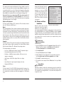
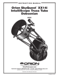
instruction Manual Orion® Parsec™ Series Astronomical Imaging Cameras Parsec 8300C (Color) #52075 Parsec 8300M (Monochrome) #52077 Parsec 10100C (Color) #52078 #52078 Providing Exceptional Consumer Optical Products Since 1975 OrionTelescopes.com Customer Support (800) 676-1343 E-mail: [email protected] Corporate Offices (831) 763-7000 89 Hangar Way, Watsonville, CA 95076 © 2008-2011 Orion Telescopes & Binoculars IN 383 Rev. B 11/11 Table of Contents 1. Introduction . . . . . . . . . . . . . . . . . . . . . . . . . . . 4 6. Multiple Camera Control for Autoguiding . . . 34 1.1. The Parsec 8300 . . . . . . . . . . . . . . . . . . . . . . . . . . . . . . 4 6.1. Autoguider Calibration . . . . . . . . . . . . . . . . . . . . . . . . . 34 1.2. The Parsec 10100C . . . . . . . . . . . . . . . . . . . . . . . . . . . . 4 7. Other Features Of MaxIm DL . . . . . . . . . . . . . 37 1.3. Feature Highlights . . . . . . . . . . . . . . . . . . . . . . . . . . . . . . 5 7.1. Information Window . . . . . . . . . . . . . . . . . . . . . . . . . . . 37 2. Getting Started . . . . . . . . . . . . . . . . . . . . . . . . . 6 7.2. Night Vision . . . . . . . . . . . . . . . . . . . . . . . . . . . . . . . . . . 37 2.1. Parts List . . . . . . . . . . . . . . . . . . . . . . . . . . . . . . . . . . . . . . . . . . . . . 6 7.3. Observatory Control Window . . . . . . . . . . . . . . . . . . . . 38 2.2. System Requirements . . . . . . . . . . . . . . . . . . . . . . . . . . 7 8. Tips . . . . . . . . . . . . . . . . . . . . . . . . . . . . . . . . . 38 2.3. Software and Driver Installation . . . . . . . . . . . . . . . . . . . 9 8.1. Polar Alignment . . . . . . . . . . . . . . . . . . . . . . . . . . . . . . 38 3. Software Walk‑Through . . . . . . . . . . . . . . . . . 10 8.2. Choosing a Site for Astro-Imaging . . . . . . . . . . . . . . . . 39 3.1. The Camera Control Window . . . . . . . . . . . . . . . . . . . . 11 8.3. Using Focal Reducers and Barlow Lenses . . . . . . . . . 40 3.2. The Screen Stretch Window . . . . . . . . . . . . . . . . . . . . . 14 8.4. Filters . . . . . . . . . . . . . . . . . . . . . . . . . . . . . . . . . . . . . . 40 4. Astronomical Imaging . . . . . . . . . . . . . . . . . . 16 8.5. USB Extension Cable . . . . . . . . . . . . . . . . . . . . . . . . . . 40 4.1. Focusing . . . . . . . . . . . . . . . . . . . . . . . . . . . . . . . . . . . . 17 8.6. Care and Maintenance . . . . . . . . . . . . . . . . . . . . . . . . . 40 4.2. Setting the Cooler . . . . . . . . . . . . . . . . . . . . . . . . . . . . . 19 9. Specifications . . . . . . . . . . . . . . . . . . . . . . . . . 42 4.3. Imaging Deep Sky Objects . . . . . . . . . . . . . . . . . . . . . . 20 5. Image Processing . . . . . . . . . . . . . . . . . . . . . . 26 5.1. Image Calibration . . . . . . . . . . . . . . . . . . . . . . . . . . . . . 26 5.2. Convert Raw to Color (For Parsec 8300C and 10100) 27 5.3. Stacking – Combining Images . . . . . . . . . . . . . . . . . . . 28 5.4. Filter . . . . . . . . . . . . . . . . . . . . . . . . . . . . . . . . . . . . . . . 32 5.5. Color Balance . . . . . . . . . . . . . . . . . . . . . . . . . . . . . . . . 32 2 3 1. Introduction Welcome to the exciting world of astro-imaging. Your new Parsec™ Astronomical Imaging Camera is capable of capturing professional quality astro-images of your favorite celestial objects. You can showcase spectacular images on your computer, share them on the internet, or print them. The camera’s large 8.3 mega-pixel array provides very high resolution images which are great for publishing in large prints. Please read this instruction manual before attempting to use the camera or install the needed software. For the most detailed information on specific camera and software functions, consult the Maxim DL Help Topics included with the CD; the tutorials found there are especially useful for familiarizing yourself with the software and camera. 1.1.The Parsec 8300 The Parsec 8300 is a high resolution, 8.3 megapixel CCD with a dual-stage, regulated thermoelectric cooler to enable maximum imaging performance. Both the 8300M and 8300C are very sensitive and capable of detecting faint deep sky objects in a short exposure; and longer exposures can reveal extremely deep fields with subtle nebulosity and galaxies in the background. The unique versatility of the Kodak KAF8300 full frame CCD lets you take advantage of the densely-packed pixel array. 1x1 mode (3326 x 2504) utilizes the full resolution of the camera, providing the most detailed images and largest possible prints. Binning in 2x2 mode (1663 x 1252) increases the camera’s sensitivity and full well capacity (meaning it can collect more light) at the expense of resolution. Binning in 2x2 mode can be especially useful for longer focal length and higher focal ratio telescopes. Note that the Parsec 8300C model will not have any color in 2x2 mode. 1.2.The Parsec 10100C The 10.7 megapixel Parsec 10100C uses Kodak’s KAI10100 interline CCD. It has the same cooling system and architecture as the Parsec 8300, but with slightly faster data transfer to accommodate the higher number of pixels (3760 x 2840 in 1x1, 1880 x 1420 in 2x2). Additionally the number of binning modes includes 1x1 (full resolution), 2x2, 3x3, and 4x4. This CCD chip offers the unique ability to image in color at 1x1 mode, as well as 2x2 mode. This is advantageous when imaging with different focal lengths. In general, the longer focal length telescopes (like RCs and SCTs) are more suited to image with in 2x2 for this particular CCD sensor, because the pixels are small. Imaging in 2x2 mode makes each pixel size the equivalent of 10.8 microns instead of 5.4 in 1x1 mode. Binning 2x2 with color cameras is normally captured in monochrome only. But the Parsec 10100C can bin 2x2 in color. 4 Tripod adapter LED 2 Power port USB port LED 1 Figure 1. Parsec ports and LEDs. 1.3.Feature Highlights • Simple interface: A USB port and power port are all that’s needed to power and connect to the Parsec (Figure 1). • Dual-stage thermoelectric cooler: Dramatically reduces thermal noise in all images. • Regulated cooling: Enables you to set the exact temperature within the cooling range of the camera. This allows you to take calibration images like dark frames at the exact same temperature as your light frames, making for the cleanest images possible. Additionally, since you can match the CCD temperature at any time (within the range of the cooler), you have the freedom to take dark frames when it’s most convenient for you, so you don’t have to use up valuable imaging time to take dark frames. • Regulated cooling fan speed: Three fan speed settings allow you to set the speed to your liking. High is the loudest but most effective setting. • Shutter: A shutter is necessary for Kodak CCD chips, but it also enables you to automatically take dark frames without having to cap the front of your telescope. This is especially useful when taking autosave image sequences. • High speed USB 2.0 interface and internal memory buffer: The full frame 32 megabyte SDRAM on-board memory ensures a clean image download each time, even if the system resources of your PC are temporarily compromised. The high-speed USB 2.0 downloads the full frame within 15 seconds depending on your computer speed. • Compact design: With a footprint of just 4" x 4" with 3" of depth, the Parsec easily fits into your imaging setup. The Parsec’s compact size also makes the camera suitable for Celestron® Hyperstar or Fastar systems. 5 Parsec LED Status Indicators LED 1 On/Idle Solid Exposing Off Reading Solid Downloading Solid LED 2 Blink Blink Solid Blink Hard carrying case Parsec 8300 Figure 2. The Parsec’s LED status indicators CD-ROM 2" nosepiece (camera ships with nosepiece attached) USB cable DC power cable with lighter plug Figure 4. Parts list Figure 3.1. The shutter is free to move when the Parsec is off. Figure 3.2. The shutter resets its position and holds firmly in place when the Parsec is powered on. • LED Status Indicator: Two LEDs on the Parsec indicate the camera power, exposure, image readout, and download (Figure 2) A Note about the Shutter The Parsec’s leaf shutter moves freely when the camera is off. You may notice the shutter in an arbitrary position when removing the dust cap from the nosepiece (Figure 3.1). This is normal and does not affect operation in any way. Once the Parsec is powered on, current is applied to the shutter’s motor and the shutter position resets and firmly holds its place. (Figure 3.2) Figure 5.1. The Parsec fits into a 2" focuser, just like a standard 2" eyepiece. Firmly tighten the thumbscrew that secures the Parsec in the focuser. 2. Getting Started 2.2.System Requirements 2.1.Parts List (Figure 4) • Parsec Astronomical Imaging Camera • 2" nosepiece (camera ships with nosepiece attached) • USB cable • DC power cable with lighter plug • CD-ROM • Hard carrying case 6 Figure 5.2. If your telescope has T-threads, remove the nosepiece from the Parsec and thread the camera directly onto the telescope. This provides the most secure connection. Telescope The Parsec can be used with most telescopes compatible with 2" format eyepieces. The camera is simply inserted into a focuser in the same way as a standard eyepiece (Figure 5.1). The camera is also compatible with 1.25" focusers that include camera T-threads, although some vignetting (edge darkening) may occur. Caution: Be sure to always firmly tighten the thumbscrew(s) that secure the Parsec in the telescope focuser, or it could fall out and onto the ground! If your telescope has T-threads for direct camera attachment, a more secure connection can be made. First, unthread the nosepiece from the Parsec camera body. This exposes the camera’s T-threads. Then, simply thread the camera onto your telescope (Figure 5.2). 7 The camera’s pixel size and sensitivity make the Parsec suitable for most telescopes. For telescopes with very long focal lengths (2000mm and greater), you can optionally bin 2x2 (see section 2. Astronomical Imaging) to utilize greater sensitivity and obtain sharper images at the expense of resolution. Note that the Parsec 8300C (color) camera will lose its color information if binning in 2x2. Because the Parsec uses a larger format CCD chip, a telescope with a 2" focuser is recommended to for full field illumination. You can still use the camera with a 1.25" focuser if it has optional T-threads; however, some vignetting (edge-darkening) may occur in the images. Backfocus Requirement The Parsec requires 29.24mm (1.151") of backfocus. This is the distance from the front of the T-threads to the CCD sensor. Mount Deep sky imaging with the Parsec requires an equatorial mount with a right ascension (R.A.) motor drive. The goal for your mount is to seamlessly track the apparent movement of the sky as the Earth rotates. The tracking must be very accurate, or the object you want to image will drift and blur across the camera’s field of view while the exposure is taken. Even a small amount of drift will cause a star to look oblong instead of a round point. We recommend using a high-quality equatorial mount which utilizes periodic error correction (PEC) or has the ability to interface with an autoguider. Computer The Parsec requires a PC to operate the camera. For astro-imaging in the field at night, a laptop computer is highly recommended. The included software is Maxim DL which requires Windows XP, or Windows Vista operating systems. The following hardware is also required: 2.3.Software and Driver Installation Figure 6. The Launcher provides an Before the camera can be used, the easy menu for software installation. software and camera drivers must be installed onto your computer. Turn on your computer and allow the Windows operating system to load as normal. Insert the included CD-ROM into your computer’s CD-ROM drive, and the Launcher will appear. This allows you to install the Maxim DL software. After the software is installed, the drivers will install automatically once the Parsec is initially connected to the computer. Do not connect the camera to your computer before you have installed the software. Software and Driver Installation To install Maxim DL: 1. Insert the CD-ROM into the drive. The Launcher will appear (Figure 6). (For Windows 7 and Vista computers, the AutoPlay window will appear first. Select Run Launcher.exe, then the Launcher will appear.) • Processor – 700 MHz speed or higher, Pentium™ III equivalent or higher 2. Click Install MaxIm DL • Recommended minimum memory size is 512 MB. 3. The Install Shield Wizard will start. Click Next. • Disk Space – 380 MB for software installation, 1GB or more to store images is recommended. 4. Read the Maxim DL License Agreement. If you agree with the terms, then select I accept the terms in this license agreement and click Next. • Video Display – 1024 X 768 or higher, 16-bit color or higher. 5. Click Install. The installation will proceed. • Mouse 6. The installation is now complete. Click the Finish button. Do not open MaxIm DL yet. • Internet Explorer 4 or higher required to display on-line help • High-speed USB 2.0 port Power The Parsec requires 12 volts DC (12VDC) with approximately 2 amperes of current. Power to the entire camera, including the thermo-electric cooler (TEC), and fan is supplied by the included power cable when plugged into a 12VDC power source. 8 Imaging in the field usually requires the use of a portable field battery to supply power, or you can use a 110VAC to 12VDC power converter if you have access to an AC outlet. Make sure the power supply provides at least 2 amperes of current. This allows the Parsec TEC to use 100% of its potential cooling power. Camera Driver Installation Now that the software is installed, the camera driver must also be installed. You must connect power to the camera and connect the USB cable from your camera to the computer before starting MaxIm DL, or the software and computer will not recognize the camera. 9 For the most detail regarding all of the features in MaxIm DL, please consult the comprehensive help tutorial in MaxIm’s Help Topics. The following section of the manual will walk you through the basic features mostly found in the Camera Control Window. Figure 7. Access the Camera Control Window from the View menu, or pressing Ctrl + W, or selecting the icon. To install the camera driver: 1. Insert the CD-ROM into the computer. The Launcher will appear (Figure 6). (For Windows 7 and Vista computers, the AutoPlay window will appear first. Select Run Launcher.exe, then the Launcher will appear.) 2. In Launcher screen, select Install FTDI. This installs the driver files for the Parsec camera. Figure 8. User Registration Window. 3. Connect the Orion Parsec to a USB port on the computer with the supplied USB cable. 4. Plug the supplied power cable into a 12VDC power source and connect the cable to the Parsec. LED status indicator and cooling fan will automatically power on. Windows will automatically detect the camera and install it onto your computer. Wait for the message to appear, Device Installed Successfully. Note: Your computer must have a high-speed USB 2.0 port available. If your computer has multiple USB ports, you will need to install the driver again if the Parsec is connected to a different USB port. The Parsec uses FTDI drivers which are WHQL certified by Microsoft for both 32-bit and 64-bit Windows operating systems including Windows XP, Vista and Windows 7. We recommend regularly checking www.ftdichip.com/Drivers/ D2XX.htm for updates. 3. Software Walk‑Through MaxIm DL 5 is a powerful imaging program which offers complete control for your Parsec camera, autoguider, telescope, and imaging accessories such as a motorized filter wheel and focuser. In addition to controlling your camera and accessories for image capture, MaxIm DL also provides all the necessary processing tools to assemble your astro-image. 10 The Parsec includes a free 60-day trial of MaxIm DL 5 Pro. Start by opening MaxIm DL, and you will be prompted with the User Registration window which requires your license information (Figure 8). Refer to the registration label on the envalope of your software CD and enter the information exactly as it is shown on the label. Once your information is entered correctly, the OK button will become available, click OK to proceed. You will only have to enter your software license once. 3.1.The Camera Control Window The Camera Control Window controls your Parsec camera, as well as your autoguider if you are using one. The window has three tabs, Expose, Guide, and Setup. Figure 9.1. The Setup tab in the Camera Control Window. Figure 9.2. The More/Less button reveals more detailed information about the camera status, such as the cooler temperature, exposure progress, and more. To access the Camera Control Window, Open MaxIm DL and go to View, then select Camera Control Window, or you may click on the icon found in MaxIm (Figure 7) or press Control + W. The Setup Tab and Connecting the Parsec (Figure 9.1) We recommend selecting More on the bottom right of the Setup (Figure 9.2) tab which will reveal more information such as the cooler status, exposure progress, and more. Camera 1 should be used for your Parsec. Camera 2 should be used for your autoguider if you are using one. To connect your Parsec camera to MaxIm DL. 1. Plug the Parsec into your computer’s USB port. 2. Plug the power cable into the Parsec, with your 12VDC power source already connected. The cooling fan and LED status indicators will automatically power on. 11 Figure 11. The Expose tab using the Exposure Preset default settings in Find Star. Figure 10. Select Orion Parsec in the pull down menu. 3. In the Setup tab in MaxIm DL’s Camera Control Window, select Setup Camera. Locate the Orion Parsec in the dropdown list and click OK (Figure 10). 4. Click Connect and your Parsec will connect to MaxIm DL. The Expose Tab and Taking your First Parsec Image We recommend becoming familiar with the Parsec during the day. Connect the camera to your telescope and focus on an object ¼ of a mile away. If you do not have enough outward focus travel to focus this closely, you may need an extension tube (available from Orion). In the Expose tab: 1. Select Find Star in Exposure Preset (Figure 11). Use the default settings and notice that X Binning/Y Binning is set to 2/Same. This cuts the resolution to 1/4 and speeds up the download time while making initial focusing easier to obtain. 2. Reduce the exposure Seconds to 0.1. 3. Click Expose and you will hear the shutter. Wait a few seconds for the image to appear. It may be over exposed or grossly out of focus. Adjust the 12 telescope’s focus and adjust the exposure time as needed to get a focused image. 4. Look at the Pixel value in the Information window while the mouse cursor is over the image. The Pixel and Average value should be well below 50000 or your image is overexposed (Figure 12). If you cannot get the Pixel value low enough during the day, you will need to reduce the aperture of your telescope by creating an aperture mask. 5. You may change the Binning X/ Binning Y to 1x1. For the Parsec 8300C, set the Frame Type to Color. Figure 12. The Information window displays detailed information about the image, including the Pixel count which can indicate if the image is overexposed. Note: Any time a setting is changed in the Exposure Preset, a * will appear next to the preset name indicating the settings are different than the default. Click the 13 Readout Mode In the Expose Tab, select Normal for the best image quality, and Fast for a quicker image download. Frame Type Choose, Light (Raw or Color for the 8300C), Bias, Dark, and Flat. Please read section 5, “Astronomical Imaging” to determine when and why to take a dark or flat. Number of pixels at brightness level arrow button next to the preset name to manage your presets, including Update Current Preset, and Save As New Preset. See MaxIm DL’s Help Topics for more detailed information. Range of brightness levels Figure 13. The Screen Stretch Window is a histogram that allows you to adjust the apparent brightness levels of an image on your screen. Fan Speed Select Camera Settings in the Expose tab (Figure 14.1) to access the fan speed, High, Medium, or Low (Figure 14.2). High is recommended for the best cooling performance. There are a large slew of settings in the Camera Control Window’s Expose tab. Please read MaxIm DL’s Help Topics which covers all the settings in greater detail. 3.2.The Screen Stretch Window The function of the Screen Stretch Window (Figure 13) is to properly map the image brightness levels captured by the camera into corresponding image brightness levels on the computer screen. A typical camera image has each pixel (light detecting site, over eight million pixels form a single Parsec image) represented as a number (from 1 to 65535) depending on brightness. This has to be mapped into the video monitor’s brightness range (from 1 to 255). It is important to set the screen stretch appropriately, or a great image may look terrible! When an image is displayed, you will notice a graph in the Screen Stretch Window. This is called the “histogram” of the currently displayed image. A histogram is a simple bar graph that shows the range of brightness in an image. Each bar in the graph represents a level of brightness; the bar to the far left in the histogram represents the dimmest pixels, and the bar to the far right is for the brightest pixels. The height of the bar is the total number of pixels at that brightness level in the image. Every image has a different histogram depending on how much of the image is bright or dark. Directly viewing the histogram of your image in the Screen Stretch Window provides an easy interface for making decisions on how the screen stretch should be set. In Maxim DL, the two parameters entered in the Screen Stretch Window are Minimum and Maximum. A pixel that is at the Minimum value is set to zero (black), and a pixel at the Maximum value is set to 255 (white). An easy way to adjust the 14 Figure 14.1. The Camera Settings is found in the Expose tab. Maximum and Minimum values is to move the slider arrows located directly under the histogram of the image in the Screen Stretch Window. The red slider arrow corresponds to the Minimum value and the green arrow corresponds to the Maximum value. Simply left-click and then drag each arrow to adjust it to the desired level. The best results are obtained by adjusting the arrows (numbers) until the most pleasing display appears. Figure 14.2. Adjust the Fan Speed in the Parsec Settings. There are also seven automatic settings in the Screen Stretch Window. Typically, Medium will give good results for deep sky objects, so the default screen stretch setting is Medium. Instead of using the Screen Stretch Window, it is faster to use the Quick Stretch facility. This allows you to modify the image appearance instantly with small up/ down and left/right movements of the mouse. To do this, hold down the Shift key, then left-click and drag the mouse on the image. You’ll find this feature to be a great convenience when fine adjusting the screen stretch to get an image to look its best. The trick with stretching is determining exactly how to stretch the image for best effect. Often there are several different possibilities for the same image. Trial-anderror will be the best way to judge what the best screen stretch setting is. Try 15 4.1.Focusing Focusing the CCD camera is one of the most critical parts of imaging. It can be challenging, but MaxIm DL has some helpful features which will assist you when focusing your Parsec. Before focusing, make sure your mount is polar aligned and tracking. For best results, we recommend focusing on a star at least 30° above the horizon (or higher). Follow these steps to achieve an accurate focus: 1. Find and center a moderately bright star through your finder scope. Try to find a star around magnitude 4 or 5. If you are not using an optical finder or just using your unaided eye, the star should look relatively faint. This is important because brighter stars will easily over saturate the camera and compromise the focus accuracy. 2. Center your telescope on the star using an eyepiece. Make sure the right ascension (R.A.) tracking motor is engaged on your mount. 3. Replace the eyepiece with the Parsec. 4. Set the Exposure Preset to in the Camera Control Window’s Expose tab to Focus. 5. Click the Expose button. You should see the out of focus star in the image. If you do not see anything, you need to increase the exposure time. Figure 15. Subframe around the star you want to focus on by drawing a box around it with your mouse. several different settings until you find one you think looks best. When the image is subsequently saved, the screen stretch setting information will be kept when the image is next opened. Feel free to adjust the Screen Stretch settings all you want; it will not effect the image data you captured and only effects how the image is displayed. You can always switch back to a preset setting, like Medium or Moon. 4. Astronomical Imaging Now that you’re familiar with basic camera and software operation, it’s time to take the Parsec out at night under the stars to capture some astronomical images. We recommend starting with the Moon, as it is easy to acquire into the camera’s field of view, and typically does not require stacking multiple exposures like planetary and deep sky images do. 6. Check that the Subframe section has both the On and Mouse boxes checked on. 7. Draw a small box around the unfocused star with your mouse (hold-click and drag the mouse cursor around the star to draw the box, Figure 15). 8. In the Expose tab, towards the right, select Continuous. Click Expose. The camera will only download the area you previously selected, which makes each image download significantly faster than the whole frame. Note: If the Parsec is grossly out of focus, no object will appear in the image, not even a blur. Increase the exposure time if needed and patiently move through the focus range of your telescope until you see the centered star come into view. 1. Gradually adjust the telescope’s focuser inward until the star visually comes to a small point on your computer screen. You have achieved a rough focus. Some small adjustments remain to get a perfect focus. 2. Click the Stop button. 3. Set Seconds somewhere between 0.1 and 3 seconds (or longer for fainter stars), depending on the brightness of your star. 16 17 a fainter star. Paying attention to these values will help you get a very accurate focus, far better than simply looking at the star image on your screen. 7. Click Stop once you reach the best focus and click Reset in the Subframe section at the bottom of the Camera Control window. Before proceeding to take images, switch back to the desired Exposure Preset. Figure 17.1. Turn the Coolers on. Note: Due to atmospheric seeing conditions, you may notice significant fluctuation in the FWHM and Max Pixel values while focusing. You typically have to take multiple exposures each time you adjust the focuser to determine the quality of your focus. Figure 16.1. Select Display Large Statistics in the Expose tab. 4. Click Expose. 5. Carefully watch the FWHM and Max Pixel values in the Camera Control Window. If you are standing several feet from your laptop while focusing, check the Display Large Statistics option in the Expose tab (Figures 16.1 and 16.2). The FWHM (Full-Width Half Maximum) indicates the diameter of the star. The Max Val is the brightness value for the brightest pixel in the star. The smaller the FWHM, and the larger the Max Pixel, the closer you are to focused. Figure 17.2. Establish a Setpoint(C) you wish to set the CCD temperature to. 4.2.Setting the Cooler The Parsec can cool the CCD to more than 35°C below the ambient temperature. But remember that the ambient temperature changes and you want to have enough cooling capacity to take dark frames at the same temperature later. To set the cooler: 1. Connect the Parsec camera with MaxIm DL in the Camera Control Window’s Setup tab. 2. In the Camera Control Window’s Setup tab, click On under the Coolers box (Figure 17.1). Figure 16.2. The Focus Statistics offer a convenient way to easily monitor your focusing while standing at the telescope several feel away from your laptop. 6. Adjust the focus as needed to get the smallest FWHM and largest Max Pixel possible. The Max Pixel should stay well below 50000, as this approaches saturation. If the Max Pixel approaches 40000-50000, reduce the exposure time or try selecting 18 Caution: Once you have achieved focus, be sure to click the Reset button in the Subframe box, otherwise the camera will crop all your images into a small square! 3. Click Cooler under the Camera 1 box and enter the Setpoint(C) you wish to cool the CCD to (Figure 17.2). Keep in mind the cooling range of the camera which is MAX 30-40°C below ambient depending on fan speed. The Setpoint(C) is the absolute temperature, so this will be the actual target temperature of the CCD camera. If you set the temperature to -10°C, the CCD chip will literally cool to 10 degrees below zero Celsius. 4. Click More/Less on the bottom right of the Camera Control Window to monitor the cooling status. After a couple of minutes the Cooler Power 19 Figure 18.1. The Autosave Setup window sets all of your options to autosave your image in a sequence. sures of 60 seconds or more also require autoguiding with a separate camera. The Orion StarShoot AutoGuider can be operated with the Parsec in MaxIm DL. To start: Figure 17.3. Monitor the Cooler Power, Sensor Temp, and Setpoint and make sure they reach your goals. should drop below 100% (Figure 17.3). If the Cooler Power does not drop below 100% after a couple of minutes, you will need to raise the Setpoint. 5. Monitor the Sensor Temp and Setpoint and make sure they match. If the Senor Temp is higher than the Setpoint, you will need to raise the Setpoint. We recommend keeping the Cooler Power to about 80% (or less) for the best performance while still having the ability to match the temperature later if needed. Pushing the cooler to near 100% will hinder the accuracy if your dark frames if the dark frame temperature does not match your light frame. 4.3.Imaging Deep Sky Objects Capturing impressive images of deep sky objects, such as galaxies, nebulae, and star clusters, require relatively long exposures. You will take several individual images and stack them together to form one high-quality resultant image. Very accurate polar alignment is essential for deep sky imaging. Stars will streak across the field of view without precise polar alignment and tracking. Longer expo- 20 1. Acquire and center the deep sky object into the field of view of your eyepiece. If you are using a mount with an accurate computerized go-to system, you can keep the camera installed in your telescope’s focuser without using the eyepiece. 2. Remove the eyepiece and replace it with the Parsec. 3. Set the Exposure Preset to Focus and precisely focus the camera. If necessary, move the telescope to a nearby star to determine the best focus. For best results, when using the Parsec 8300C, select Light Raw for Frame Type so you can properly calibrate your astro-images later, see section 5, “Image Processing”. For Parsec 8300M users, simply choose Light for Frame Type. 4. In the Expose tab, set Seconds to 10-20 and click Expose. After the image downloads check to see if the deep sky object is centered well in your camera. Adjust the camera orientation if needed, keeping in mind that you may have to refocus the camera after making the adjustment. Reposition the telescope if needed to center the deep sky object. 5. Set the Exposure Preset to LRGB, even if you are using the Parsec 8300C. You can always rename the Exposure Preset with your custom settings. 6. Click the Autosave button, and select your exposure times, and frame type (Figure 18.1). 21 Figure 18.2. Select Set Image Save Path. 7. Select the file folder in which you would like to save the images with Select Image Save Path found by clicking the arrow in the Autosave Setup window (Figure 18.2) and set the name of the file in Autosave Filename. Typically the name of the object being imaged, such as “OrionNebula1”, will be entered here. If “OrionNebula1” is the Autosave Filename, and you choose to save five images, then the images will appear in the selected file folder as “OrionNebula1_0001. fit”, “OrionNebula1_0002. fit”, “OrionNebula1_0003.fit”, “OrionNebula1_0004.fit”, and “OrionNebula1_0005.fit”. Try exposures of 30-60 Seconds to start. Figure 20. Set the Type to Dark in the Autosave Setup window. (background noise level), read noise (noise introduced during camera readout and download) and hot pixels (bright dots in the image). All of this noise exists in your raw astro-image too, which distracts from the detail you want to see. To eliminate most of the camera noise, you can take several dark frames, average them, then subtract them from your astro-images, also called, “light” images. Note: Make sure the cooler set point and CCD temperature are the same as they were when you took your light frames. To take dark frames for subtraction from “light” images: Figure 19. A dark frame contains the thermal and background noise, as well as any read noise. The same noise appears in your “light” images. Dark frames isolate the noise so it can later be subtracted from your “light” images. 8. Click Expose, and the camera will commence taking the images. Note: When the camera is taking long exposure images, it is critically important not to touch, shake, or otherwise disturb the telescope, or a blurred image will result. Also, make sure no surrounding light shines into the telescope during the exposure. Dark Frames Dark frames are images taken with no light coming into the camera. A dark frame is typically taken with the telescope’s objective capped. The only data in the image is the inherent camera noise (Figure 19). The noise contains the dark current 22 1. Set the Frame Type in the Camera Control Window’s Expose tab to Dark. Or if you are taking a sequence of images, set the Type in the Autosave Setup window to Dark (Figure 20). Even though MaxIm DL will already know which of your images are dark frames, it’s a good idea to assign a preset, such as D to better organize your different images. Note to Parsec 8300C and 10100 users: You must take Raw Light frames in monochrome BEFORE converting to color in order to utilize dark frames. 2. Use the same exposure time as the “light” images you have or will take. If your “light” image is 60 seconds, the dark frame must also be 60 seconds. 3. Set the number of dark frames you would like the camera to take under (3 to 10 will generally suffice, as these will be averaged together). 4. Click OK, and proceed to click Expose in the Expose tab. Since the Parsec has a shutter, you to not need to be present when the dark frames are taken, it will occur automatically during the sequence! 23 Flat Fields A flat field is an image taken with uniform featureless light entering the telescope, such as a blue sky in the early morning or after sunset. Flat fields solve a number of issues in your astroimages. 2. Point the telescope at a uniform and featureless light source, like the sky at dusk or dawn, or a blank white sheet of paper. Make sure the camera orientation is exactly the same as it is or was for astro-imaging (Although the telescope is pointing at a featureless surface, the focus and orientation must be set as it normally would be for astro-images.) Vignetting Vignetting (Figure 21.1) in a telescope reveals edge-darkening in the astroimage. The large CCD chip in the Parsec can easily detect vignetting through almost any telescope, even specialized astrographs. Vignetting is more apparent when the telescope’s illuminated field is not large enough to illuminate the full area of the CCD chip. As a result, more light is detected in the center of the image compared to the edge. Figure 21.1. Larger format CCD cameras like the Parsec reveal vignetting through most telescopes. Vignetting occurs when the edge of the image plane has less illumination than the center. Dust and Particles Dust and particles (Figure 21.2) will inevitably show up in your raw astroimages. Large particles on the CCD Figure 21.2. Dust or other particles on optical window sometimes look like the camera’s optical window can show up unfocused circles or doughnuts in your as distracting dark shapes in your images. images. It’s too late to clean your camera if you are already imaging in the field at night. And even when the camera is clean, dust usually finds a way to show up in your images. Telescope Artifacts Very large particles or other artifacts in your telescope can effect your astro images. Insufficient telescope baffling or poor collimation can also cause unsymmetrical field illumination in your images. To take a flat field image: 1. Ensure that the telescope is focused and ready for astro-imaging. 24 3. Set the Frame Type in the Camera Control Window’s Setup tab to Flat. Or if you are taking a sequence of images, set the Type in the Autosave Setup window to Flat. Even though MaxIm DL will already know which of your images are flat frames, it’s a good idea to assign a preset, such as F to better organize your different images. 4. Set the Seconds to 0.1 for now and click OK, then Expose. You want the Max Pixel to read somewhere around 20000. Adjust the exposure time as needed until the Max Pixel is close to 20000. It’s a good idea to take several flat frames and try different exposure times until you find the correct exposure. If you are taking your flats near dusk or dawn, the sky brightness will changes rapidly. The flat fields also need dark frames. 5. Add another Slot sequence in Autosave Setup and select Dark under Type. Select the same exposure time as your flat and assign a prefix such a FL. 6. Click OK then Expose. Note that you can set all of your lights, darks, flats, and dark flats at the same time in the Autosave Setup window to make the sequence faster and more convenient. Once you get used to all of these features, you will be able to set all of the frames you want in Autosave Setup window without having to go back to add more frame types. Light and Dark 2x2 Modes For added convenience and versatility, the Parsec’s individual pixels (lightdetecting sites) can be “binned” into units of two-by-two pixels (i.e. four individual pixels create one binned 2x2 pixel). This creates larger and more sensitive pixels, but with decreased resolution. This can be useful for some types of astronomical imaging, such as capturing faint nebulae. It can also be useful for quickly checking the image centering and orientation before using the full resolution to actually capture images. To use in “2x2” mode, select X Binning/Y Binning to 2x2/Same. Note to Parsec 8300C users: By binning the images in 2x2, you will bypass the RGB filter built into the camera; so the resulting binned images will be black and white, without the ability to convert to color. 25 Figure 22.1. Before your images are Figure 22.2. Combining multiple deep combined, an individual deep space image will have more noise and less detail. space images greatly increases the detail in the resulting combined image Each individual deep sky image is faint and has a noticeable amount of noise. Combining the individual deep sky images eliminates the noise and enhances the detail in the deep sky object by improving the signal to noise ratio. The more images you combine, the better the resulting image will look. (Figures 22.1 and 22.2). Read section 5 “Image Processing” to utilize MaxIm DL’s Stack function. 5. Image Processing After you have captured and combined individual images (with or without dark frame subtraction) into a single resultant image, you may want to perform some additional image processing to bring out subtle details or to make the image appear more pleasing overall. MaxIm DL contains several image processing functions which will further enhance your image once your individual images have been calibrated and combined. The image processing functions are found in the Process menu. Figure 23. The Set Calibration window lets you automatically select all of your calibration images. 5. Click OK. The darks and flats you previously saved will be subtracted from your “light” images. 6. With your astro-image open in MaxIm DL, select Calibrate from the Process menu (or click the Calibrate icon in MaxIm DL) You should see a significant amount of noise disappear. This process can be automated for all of your light images, see “Stacking – Combining Images”. 1. Select Setup Calibrate from the Process menu. 5.2.Convert Raw to Color (For Parsec 8300C and 10100) 2. Click Clear All Groups if any filenames appear in the window. Once you have calibrated your images, you need to convert them to color: 3. Select the Source Folder where you saved your dark frames (Figure 23) 1. Open the raw images you wish to convert to color. If you need to convert more than 5 images or so, please refer to “Batch Processing” as this method allows you to combine an unlimited number of images without consuming more memory from your computer. 5.1.Image Calibration 4. Click Auto-Generate and MaxIm DL will automatically find all of your calibration images such as darks and flats. The selected dark frames will now appear in the pop-up window. 2. Select Convert Color in the Process menu. 26 27 6. The Tree View on the left side of the Stack dialog will now show all the image files you have selected, arranged into groups according to their FITS header. You can open the groups to view the files by clicking on the + sign. If you would like to view an individual file, rightclick it and select Display Image. Alternatively, using the right-click menu select Auto Display, and any image you click on will be automatically displayed. 3. Select Orion Parsec High Quality in the Select Camera pull down menu (Figure 24). 4. Click OK and the image should appear in color. You can make several adjustments to the Color Balance if needed (see “Color Balance”). 5.3.Stacking – Combining Images Combining individual deep sky images enhances the detail in the deep sky object by improving the signal to noise ratio. We will demonstrate stacking LRGB images; however, a similar process works for monochrome, one-shot color, and RGB image sets. Figure 24. The Convert Color window converts raw images taken from the Parsec 8300C to color. 1. Select the Process menu Stack command (Figure 25) 2. On the Select tab, turn on Classify by OBJECT and FILTER. 3. Click the FILTER button to set up the filter mapping. This will determine what filters are mapped into which LRGB color channels. To change a row, click once on the row, then click once on the Filter Color item, and enter a new value. This will make sure that your filters are automatically assigned to the correct group (Figure 26). Figure 25. The Stack window is a powerful feature which automatically calibrates, sorts LRGB filtered images, and 4. If your images have not yet been combines your astroimages. calibrated, turn on Mark added images as Auto Calibrate. Each image will automatically be calibrated as it is needed, using the settings from the Set Calibration command. 5. Click the drop list on the multi-function button and select Add Folder. Browse to a folder on disk where your images are located. This folder may contain images of several different targets, as long as the OBJECT FITS keyword is set in each image (during imaging, this is automatically obtained from the Observatory Control window if a telescope is connected). 28 Figure 26. Filter Channels. 7. If necessary, you can move images or entire groups by dragging them. You can set properties for groups or individual files using the right-click menu. 8. Select the Quality tab (Figure 27). If you would like to eliminate images with out-of-round stars caused by bad tracking, turn on the Roundness check box. The Threshold should be set to limit how far out of round the star can be; for example, 0.1 will throw out any image with stars that are more than 10% out of round. Click the Measure All button, and any bad images will automatically receive an X in the enable box. You can manually override this decision if you like, by changing the enable box. 9. Select the Align tab (Figure 28). If your images have been solved using PinPoint Astrometry you may wish to use the Astrometric align mode, which is extremely accurate. Alternatively, the Auto Star Matching mode is fully automatic and quite accurate. There are a variety of other alignment modes available, including manual alignment. Figure 27. The Stack window can measure the image quality and automatically reject the ones which are not good enough to combine. Figure 28. The Align tab can automatically align (register) your images by using Auto Star Matching or Astrometric functions. 29 command before opening them with the Open command. Alternatively, you can simply drag and drop them from Windows Explorer onto the MaxIm DL window. 10.You can select one of the images to be the Reference Image, using the right-click menu. This image will not be shifted during alignment; all other images will be aligned to it. If you do not select the reference image, the first image in the list will be used. 11.Select the Color tab (Figure 29). If you wish to customize the color balance settings you may do so; otherwise click the Defaults button, which assumes 1:1:1 color balance. Also turn on Auto equalize background to remove any background color cast due to sky glow. 12.Select the Combine tab and set the Combine Method (Figure 30). For large numbers of images we recommend using Sigma Clip; a Sigma Factor of 3 is a good starting point. If you have a modest number of images the SD Mask mode will produce a better result (but will take more time); a good starting point for the settings is a Sigma Factor of 0.5 and a Number of Passes of 3. Tip: Once you have all the settings the way you like them, you can simply dump in the images and click the Go button. You can also drag-and-drop images onto the Tree View from the Windows Explorer, or select files individually. When you use the Add Folder option calibration files are automatically ignored; the other methods for adding files will include them. Usually you don’t want to stack the calibration files automatically, since the Set Calibration command does that for you with proper normalization, etc. Figure 29. The Color tab. 1. Average sums all the pixels and divides by the number of images chosen to combine. 2. Sum adds up all the pixels in the images. This will increase the Max Pixel value and the offset in the Screen Stretch window. If you Sum the image, the file should be saved as a fit in IEEEFloat (beyond 16 bits) to preserve all the data in the image. Figure 30. The Combine tab lets you select the different combine methods such as SigmaClip or Average. 13.Be sure to turn on Ignore Black Pixels. If there are any areas where the images do not completely overlap, this will ignore the contribution from the missing data. Otherwise you may get strips across the edges of the image that look dimmer. 14.Set Normalization to Linear and set Area to 50%. This setting assumes that any changes in intensity between the images are due to extinction rather than changes in background level. If you have strong background level changes you may want to use Delta-Level instead. 15.Select whether you want the results created as new images or written to a disk folder using the commands in the Options menu. 16.Click Go to start the stacking process. This may take some time; you can interrupt and restart the process if needed. If you have multiple image groups, they will be stacked separately. Color sets will automatically be color combined. To view results written to a folder, you must close the Stack 30 There are several methods that will achieve slightly different results when stacking images, such as, Average, Sum, Median, and Sigma-Clip. Each of these methods will improve your image buy stacking it, but each one combines the images in different ways. 3. Median takes the middle pixel value from all of the images. The Median mode is useful when some pixels are extremely bright or dark (hot/dark pixels, cosmic ray hits). If Median mode is used, a Normalize option is available. Normalize will remove differences in the image scaling which could interfere with the median processing. 4. Sigma-Clip combines the best features of Average and Median. SigmaClip is the best choice for removing unwanted noise, hot pixels and satellite trails. It works like Average but also calculates the standard deviation of the averaged pixel values. The Sigma Factor will determine how many pixels from the standard deviation are discarded. The lower the Sigma Factor, the more pixels are discarded. 3.0 is a good value to start with. A new average is calculated without the discarded pixel. This value is assigned to the corresponding pixel in the output image. 5. SD Mask is a custom variation on Sigma Clip contributed by Ray Gralak. This is an iterative algorithm that more effectively removes outlier pixels while preserving “good” pixels. It is most useful when the number of images available is too small for effective use of Sigma Clip. 6. Drizzle is a method intended for combining undersampled, dithered images developed by Andy Fruchter (Space Telescope Science Institute) and Richard Hook (Space Telescope European Coordinating Facility). This process, formally called Variable-Pixel Linear Reconstruction, can restore 31 the Preview Image to see how altering these parameters will affect your image (or click the Full Screen button to see the changes applied to your full image). detail finer than the pixel size of the frames being combined. The technique is described at http:// xxx.lanl.gov/abs/astro-ph/9808087. Note for the Parsec 8300M: Before any color balance adjustment can be made, you must first Combine Color to each individual LRGB or RGB images. 5.4.Filter Color images from CCD cameras typically require a background level adjustment. This is accomplished by bringing the background level (or bias) in each color plane down to zero. Each of the Background Level values is subtracted from every image pixel in its color plane. Any pixel values that become negative are forced to zero. The Auto button automatically determines the settings necessary to equalize the image background in all three color planes. The Reset button resets the background level subtraction to zero on all planes. Filtering an image is an operation that emphasizes certain characteristics of an image while suppressing others. MaxIm DL supports several kinds of Filters, such as: Unsharp Mask, Kernal Filters, and Digital Development, available from the Filter menu. Please read MaxIm DL’s Help Topics for the most detailed information about the various image processing filters available. The following are just some of the many processing filters available in MaxIm DL. Figure 31. The Color Balance Window. Unsharp Mask is a method of sharpening or high-pass filtering an image. It amounts to subtracting a low-pass filtered version of an image from itself. The low-pass filtered version is called the mask. Kernal, High-Pass Filter can be set to More or Less for different effect. The HighPass Filter can be useful for accentuating fine details in an image. Kernal, Gaussian Blur is a method of blurring an image. It can be used to suppress noise in an image at the expense of sharpness. The Radius setting controls the amount of blurring applied to the image. Increasing the radius increases the amount of blur applied. For best results, turn on the Auto Full Screen preview button, and adjust the settings. This allows you to rapidly adjust the settings until you are satisfied with the results. Then, click OK to actually apply the filter settings to the image. It is best to use a light touch with this command, to avoid over-processing the image. Over-processing can create artifacts; i.e. features in the image that are not real. It also amplifies the noise in the image. 5.5.Color Balance The sensitivity of most CCD cameras as a function of wavelength (color) is different from the response of the human eye. The filters used for creating color composites also have their own characteristics, as do the telescope optics. Although “perfect” color rendition is an elusive if not impossible goal (all individuals see colors slightly differently), it is straightforward to get “good” color balance with simple weightings. This is where the Color Balance command (in the Process menu, Figure 31) comes in handy to touch up the resultant colors in your images. Use 32 Scaling adjustment (entered as a percentage) allows you to compensate for transmittance differences between the filters used to acquire the three color planes. Values of 100% result in no change. The scaling percentages can be typed in or adjusted using the “spin” controls (small up and down click arrows to the right of the scaling numbers). The Preview Image is particularly helpful in monitoring the results when using the spin controls. The Reset Scaling button resets to 100% on all three planes. The Click On White Area to Set Scaling check box enables the operation of the mouse to set the scaling. Set the Background Level first (you can use Auto), then click on a white object (e.g. a neutral-colored star) in the image (not the Preview Image) with the mouse. The Scaling settings will automatically be adjusted to make the selected point appear white. If an area of the image is known to be white (or gray), this is an easier way to determine the scaling factors, and can be used to instantly color balance the image. Note on File Format When saving individual images that were not taking during a sequence (using Save or Save As in the File menu), you have a choice of file formats. The default produces .fit files, but .tif, .jpg, .png, and .bmp file formats can also be selected. Having a choice of output file formats is useful, especially if images will be exported to other software programs for additional image processing (like Adobe Photoshop, for instance). If you save to a file format other than .fit, you will need to check the Auto Stretch box, or otherwise Stretch the image to change the Output Range (in the Stretch command window) to match the Size Format (in the Save As window). Otherwise, the Output Range will likely exceed the Size Format, and the saved image will be ruined (will turn all white). For example, say the Output Range is set to create image brightness values in 16-bit format, while the Size Format of a specific file format (.jpg, for example) may only support 8-bits. Since the 16-bit format sees 65535 brightness levels, and the 8-bit format can only support 255 levels, all of the levels above 255 in the 16-bit image (i.e. the vast majority of the 16-bit brightness levels) will be saved at the maximum 8-bit value of 255. So the saved .jpg will have very little brightness 33 information from levels 1 to 254 and almost all the brightness information at level 255. Thus a white image results. If you plan to do all image processing within MaxIm DL Edition (or the optional full version of MaxIm DL), saving images in the FITS (.fit) File Format using the IEEE Float Size Format is recommended. This ensures that all saved data will be kept intact. If another Size Format is utilized, there may be some loss of data, especially when saving combined images. 6. Multiple Camera Control for Autoguiding One very nice feature of the MaxIm DL software is the ability to control two cameras simultaneously. This way, you only need one computer and software program to image and autoguide at the same time. This feature is also compatible with older SSDSI cameras. 1. Plug both cameras, one at a time, into the USB ports on your computer. Install the drivers for each camera as detailed prior in this instruction manual. 2. Open the MaxIm DL software. In the Camera Control Window’s Setup tab that appears, select the imager as Camera 1 and the autoguider as Camera 2, then click Connect. 3. Click on the Guide tab, Camera 2 will be assigned here. 6.1.Autoguider Calibration If you are using a second camera as an autoguider, you must calibrate the system. The exact orientation of the camera, the focal length of the guide telescope optics, and the speed of the motor drive all affect the calibration. To perform autoguider calibration: Figure 32. The Guider Settings configure your autoguider in MaxIm DL. each axis. The Calibration Time determines how long it activates the motors each time. The usual value is 5-10 seconds; start out with a value of 5. 5. Make sure all of the Guider Enables boxes are checked. 1. Switch to the Guide tab. 6. For Autoguider Output, set Control Via. If you are using the Orion StarShoot AutoGuider for example, choose Guider Relays. 2. Set the X and Y Aggr (aggressiveness) to 8 to start with. Set the Exposure to 1.0 second. Under Guide Star, make sure the Watch box is checked. 7. Click Apply. You can leave this dialog box open, or Close it if you wish. Note: The X and YAggr (aggressiveness) controls on the Guide tab allows you to adjust how vigorously star motions are tracked out in each axis. An aggressiveness setting of 10 means that the Parsec attempts to track out 100% of the motion, whereas a setting of 1 means that the Parsec only tracks out 10% of the motion. Usually a setting of around 8 or 9 provides the best tracking, since it reduces overshoot and helps ignore random motions due to atmospheric seeing and wind loads. You should experiment to determine the best setting for your particular telescope. 3. Click the Settings button (Figure 32). 4. Maxim DL needs to know how fast the telescope moves in right ascension (R.A.) and declination (Dec.) when the autoguider commands are issued. To do this, the software will Calibrate the mount by moving it back and forth on 34 8. Make sure that the telescope mount is set to move at 1X sidereal or slower. For some mounts, you must set the guide rate manually. The maximum usable rate is 1X sidereal. If your mount does not drift quickly, you can set the speed slower than 1X depending on your imaging configuration. 9. On the Guide tab, set to Expose, and click the Start button. A single image will be taken. Ensure that a well-focused bright star (near the actual object to be imaged) appears in the image. If not, adjust the guide scope and try again. Make sure the star is roughly centered. Note: The algorithm can be confused if another star appears in the frame; to minimize this risk, calibrate on an isolated bright star. 10.Now, set to Calibrate, and click the Start button. A series of five exposures will be taken; each time the telescope will be moved slightly. If the telescope 35 does not move, check the Settings. Remember, you have to set up a method for sending the autoguider commands to the telescope! 11.The star should move in an L shape. If it does not move enough, a warning message will appear. The recorded positions will be displayed in the scrolling log, along with any error messages. Note: If the star does not move far enough, or moves too far (i.e. the star leaves the field), the duration of the calibration move commands can be adjusted by clicking the Settings command and changing the Calibration Time fields (measured in seconds). A longer calibration time will increase the motion of the star; a shorter time will decrease the motion. Typical values range from five to ten seconds, depending on the correction speed, focal length, and pixel size. 12.Once you have successfully calibrated, switch to the Track mode. Click Start, and watch the star. It should move to the center of the small track box, and whenever it drifts off it should be pulled back again. You can zoom in the window for a better look. Also the tracking errors will be displayed in the scrolling log. 13.If the star bounces back and forth, reduce the aggressiveness for that axis. If it corrects too slowly, increase the aggressiveness. Changes to the aggressiveness settings take effect immediately. You are now ready to take a long-exposure image through the main telescope and imaging camera. The Parsec will continuously send small correction factors to the mount’s motor drive to insure steady and accurate tracking throughout the duration of the exposure, however long that may be. Other Autoguiding Notes: • If you are using a German equatorial mount you must calibrate with the tube on the same side of the mount as it will be when actually imaging. • The calibration settings need changing if you move the telescope in declination by more than about five degrees. Select another bright star, and Calibrate again. • If you experience bad guiding in declination and cannot resolve it through adjusting the calibration or aggressiveness, you may have a stiction problem with your declination drive. Watch which way the star drifts, and turn off the Guider Enable checkbox (in the Settings window) that pushes the star in that direction. That will prevent the stiction cycle from happening. • Make sure that any backlash compensation in the mount is turned off. • On most telescopes, the Right Ascension drive likes to have some load pushing against sidereal tracking. If the mount is balanced such that it is pulling the mount forwards slightly, the gear teeth may bounce back and forth resulting in terrible guiding that cannot be corrected by an autoguider. Be sure to always balance the telescope such that it “lifting the weight” rather than “allowing it to fall”; i.e. heavier on the East side. Note that this may require balancing the telescope differently when it is pointed East versus West. 7. Other Features Of MaxIm DL This manual only covers a small fraction of all the capabilities and features of MaxIm DL. We strongly recommend reading through MaxIm DL’s Help Topics for more detailed information about all of the features once you have become more familiar with setting up and using your Parsec camera. 7.1.Information Window The Information window displays numerical information about selected areas of the image. The window can be switched on and off using the Information Window command on the View menu, or by using the cursor button on the Toolbar. The window can remain open as a floating toolbox without interfering with other commands. The Information window has four modes of operation: Aperture, Region, Area, and Astrometric. There is also a Magnitude display that can be calibrated to show accurate stellar magnitudes. Except in Area mode, the mouse cursor will change to a crosshair and “bullseye” when the Information window is active and the mouse is over the selected image or preview. The sizes of the various elements of the circular cursor can be changed using the mouse with the right-click menu. To lock the cursor at a specific position and freeze the information display, double-click on the image. When locked, the circular cursor can be moved using the arrow keys. You can then copy text from the status area of the Information window to the clipboard using the mouse and CTRL-C (or right-click the mouse in the status area and select Copy from the resulting context menu). To restore normal operation, click the mouse again on the image. Numbers exceeding one million are shown in scientific notation; a lower case e followed by an integer means the preceding quantity must be multiplied by that power of ten. 7.2.Night Vision Selecting Night Vision toggles the night vision mode on and off. Three types of night vision display are available, selected by a dropdown on the General tab of the File Settings dialog: 36 37 Red helps maintain the human eye’s dark adaptation, Blue is the color to which most CCD cameras are least sensitive, and Dim maintains the color display but reduces the overall intensity to about one-eighth normal. • In red mode, all menus, dialog boxes, etc., are switched to red. Monochrome images are displayed red, but color images are displayed in their normal colors. This allows the user to inspect a color image without switching the entire screen back to normal colors. Red light helps maintain the human eye’s dark adaptation because it does not as readily destroy the “visual purple” photosensitive pigment of the scotopic vision system (“rod” cells). • In blue mode, all menus, dialog boxes, and monochrome images are shown in blue. As before, color images are displayed in their normal colors. The blue mode is useful when imaging with CCD cameras because it is the band in which most CCD cameras are least sensitive. • In dim mode, all menus, dialog boxes, and images (both monochrome and color) are displayed at approximately one-eighth normal brightness in order to reduce ambient light conditions in the observatory. 7.3.Observatory Control Window The Observatory Control Window provides comprehensive control and status for any other astro-imaging accessory you might be interfacing with your computer, including: • Telescope mount control with auto-center • Focuser control with autofocus • Rotator control with FOV slaving • Dome control with telescope slaving • A simple but powerful planetarium with image overlays, FOV overlays • Extensive searchable catalogs The Observatory Control Window is resizable using the mouse. 8. Tips 8.1.Polar Alignment Good telescope mount polar alignment is of critical importance for long-exposure CCD imaging. Inaccurate polar alignment leads to image movement over time (even with motor drives running and engaged), which limits the amount of time an exposure can be taken before the stars begin to streak and blur. If your equatorial mount uses a polar axis finder scope, we highly recommend utilizing it for polar alignment. If not, a technique known as the “drift method” of polar alignment has been used for many years, and can achieve an extremely accurate polar alignment. Unfortunately it is very time consuming, since the drift of a star 38 over time must be observed. The basic idea is to let the telescope mount track while watching a star to see which way the star drifts. Note the direction of the drift, and correct by moving the mount in the appropriate direction. To perform the drift method of polar alignment: 1. Do a rough polar alignment by pointing the R.A. axis of the mount at Polaris (the North Star). 2. Find a bright star near the meridian (the imaginary line running northto-south through zenith) and near the celestial equator (zero degrees declination). Point the telescope at this star, and center it in an illuminated reticle eyepiece (available from Orion). If you don’t have an illuminated reticle eyepiece, use your highest- magnification eyepiece. 3. Determine which way is north and south in the eyepiece by moving the telescope tube slightly north and south. 4. Now, let the mount’s motor drive run for about five minutes. The star will begin to drift north or south. Ignore any east-to-west movement. 5. If the star drifts north, the telescope mount is pointing too far west. If the star drifts south, the telescope mount is pointing too far east. Determine which way the star drifted and make the appropriate correction to the azimuth position of the mount. Rotate the entire mount (and tripod) slightly east or west as needed or use the azimuth adjustment knobs (if your mount has them) to make fine adjustments to the mount’s position. 6. Next, point the telescope at a bright star near the eastern horizon and near the celestial equator (Dec. = 0). 7. Let the telescope track for at least five minutes, and the star should begin to drift north or south. 8. If the star drifts south, the telescope mount is pointed too low. If the star drifts north the telescope mount is pointed too high. Observe the drift and make the appropriate correction to the mount’s altitude (or latitude); most mounts have some sort of fine adjustment for this. Repeat the entire procedure until the star does not drift significantly north or south in the eyepiece. When this is accomplished, you are very accurately polar aligned, and should be able to produce good (unguided) images of up to several minutes long, assuming the mount’s drives track well with little periodic error. 8.2.Choosing a Site for Astro-Imaging Once you have a focused image, you may find your image shifting and washed out. This can be caused by many environmental factors. Poor seeing (movement of molecules in the air, such as heat rising) and poor transparency (moisture, smoke, or other sky contaminants) will all serve to reduce image quality. That is why most major astronomical telescopes are on high mountains in thin air, to get above much of the transparency and seeing problems. Also, wind will move your telescope and affect images. Your eyes viewing through an eyepiece can change 39 slightly to compensate for disturbances like these, but the camera can not. Keep these factors in mind when choosing an observing site for astronomical imaging. For the best astro-images, we recommend finding a location with dry air, some altitude, and away from city or streetlights. Even a nearby hilltop in the countryside can provide better viewing conditions than many convenient backyard locations. 8.3.Using Focal Reducers and Barlow Lenses Focal reducers and barlow lenses change the effective focal length of a telescope. These lenses are inserted between the camera and telescope when imaging to change image scale. Focal reducers serve to decrease the focal length of your telescope. This increases the field of view seen by the camera (decreases camera magnification). This can be very useful for obtaining images of wide-field deep sky objects, such as the Andromeda Galaxy or the Pleadies star cluster. Focal reducers will usually thread onto the nosepiece of the Parsec. Any quality optical lens cleaning tissue and optical lens cleaning fluid specifically designed for multi-coated optics can be used to clean the glass surface of the Parsec’s optical window. Never use regular glass cleaner or cleaning fluid designed for eyeglasses. Before cleaning with fluid and tissue, blow any loose particles off the surface with a blower bulb or compressed air. Then apply some cleaning fluid to a tissue, never directly on the optics. Wipe the optical surface gently in a circular motion, then remove any excess fluid with a fresh lens tissue. Oily fingerprints and smudges may be removed using this method. Use caution; rubbing too hard may cause scratches. Store the Parsec in the included hard carrying case. Keep the camera in a dry location away from direct sunlight. Barlow lenses increase the focal length of your telescope, which makes the camera’s field of view narrower (increases camera magnification). This is useful for planetary imaging. Keep in mind that when the focal length is doubled, the image will become four times dimmer, so a longer exposure may be necessary. Barlow lenses are generally inserted in the focuser’s drawtube and secured with the thumbscrew on the focuser’s drawtube, and the Parsec’s nosepiece is inserted into the barlow and secured with the thumbscrew on the barlow lens. 8.4.Filters Any standard Orion 2" filter will thread into the 2" nosepiece of the Parsec. Light pollution filters, or special light pollution filters designed for imaging (such as the Orion SkyGlow Imaging Filter) improves image contrast from urban areas with severe light pollution. For the Parsec 8300M, we recommend using a motorized filter wheel, such as the Orion Nautilus to easily manage LRGB or narrowband filters to assemble a color image. 8.5.USB Extension Cable Most imaging setups may require extra distance to comfortably reach from Parsec to the computer. We recommend purchasing a 10’ USB extension cable if you need more cord length (available through Orion, check the catalog and/or www. OrionTelescopes.com). Do not exceed 20’ of cable length or you may start to experience connection problems. 8.6.Care and Maintenance When the Parsec is not in use, the dust cap should be replaced on the end of the nosepiece. This prevents dust from accumulating on the Parsec’s optical window. If significant dust does accumulate on the optical window, or the optical surface is touched, then it should be cleaned. 40 41 9. Specifications Parsec 8300 CCD Sensor (Parsec 8300C) Kodak KAF-8300CE Parsec 10100C CCD Sensor Kodak KAI-10100-CXC CCD Sensor (Parsec 8300M) Kodak KAF-8300-AXE CCD detector size 17.86mm x 13.49mm CCD detector size 17.96mm x 13.52mm Sensor format 22.5mm diagonal Sensor format 22.5mm diagonal Pixel array 3760x2840 (10,678,400 total) Pixel array 3326x2504 (8,328,304 total) Pixel size 4.75µm x 4.75µm Pixel size 5.4µm x 5.4µm Exposure range 0.002 seconds to infinity Exposure range 0.002 seconds to infinity A/D conversion 16 bit A/D conversion 16 bit Binning 1x1, 2x2, 3x3 and 4x4 Binning 1x1 and 2x2 Full Well Capacity 25,000e- Full Well Capacity 25,500e- Read Noise (RMS) 9e- Read Noise (RMS) 8e- Dark Signal (at 0ºC) 0.15e-/pixel/second Dark Signal (at 0ºC) 0.15e-/pixel/second Thermoelectric cooling 40°C below ambient temperature Thermoelectric cooling 40°C below ambient temperature Operating Power Range 10VDC to 13.8VDC Operating Power Range 10VDC to 13.8VDC Camera current draw Approximately 2A (at 12VDC) Camera current draw Approximately 2A (at 12VDC) USB connection 2.0 High speed USB connection 2.0 High speed IR-cut filter Yes IR-cut filter (Parsec 8300C) Yes Optical window Fully coated with anti-reflection coatings IR-cur filter (Parsec 8300M) No Backfocus Distance from T-threads 29.24mm (1.15") Optical window Fully coated with anti-reflection coatings Weight 900g (32 oz) Backfocus Distance from T-threads 29.24mm (1.15") Autoguider capability Yes Weight 900g (32 oz) Mounting 2" nosepiece or T-thread Autoguider capability Yes Mounting 2" nosepiece or T-thread 42 43 This device complies with Part 15 of the FCC Rules. Operation is subject to the following two conditions: (1) this device may not cause harmful interference, and (2) this device must accept any interference received, including interference that may cause undesired operation. Changes of modifications not expressly approved by the party responsible for compliance could void the user’s authority to operate the equipment. Note: This equipment has been tested and found to comply with the limits for a Class B digital device, pursuant to Part 15 of the FCC Rules. These limits are designed to provide reasonable protection against harmful interference in a residential installation. This equipment generates, uses and can radiate radio frequency energy and, if not installed and used in accordance with the instructions, may cause harmful interference to radio communications. However, there is no guarantee that interference will not occur in a particular installation. If this equipment does cause harmful interference to radio or television reception, which can be determined by turning the equipment off and on, the user is encouraged to try to correct the interference by one or more of the following measures: Reorient or relocate the receiving antenna. Increase the separation between the equipment and receiver. Connect the equipment into an output on a circuit different from that to which the receiver in connected. Consult the dealer or an experienced radio/TV technician for help. A shielded cable must be used when connecting a peripheral to the serial ports. One-Year Limited Warranty This Orion Parsec Astronomical Imaging Camera is warranted against defects in materials or workmanship for a period of one year from the date of purchase. This warranty is for the benefit of the original retail purchaser only. During this warranty period Orion Telescopes & Binoculars will repair or replace, at Orion’s option, any warranted instrument that proves to be defective, provided it is returned postage paid to: Orion Warranty Repair, 89 Hangar Way, Watsonville, CA 95076. If the product is not registered, proof of purchase (such as a copy of the original invoice) is required. This warranty does not apply if, in Orion’s judgment, the instrument has been abused, mishandled, or modified, nor does it apply to normal wear and tear. This warranty gives you specific legal rights, and you may also have other rights, which vary from state to state. For further warranty service information, contact: Customer Service Department, Orion Telescopes & Binoculars, 89 Hangar Way, Watsonville, CA 95076; (800) 676-1343. Orion Telescopes & Binoculars OrionTelescopes.com 89 Hangar Way, Watsonville, CA 95076 Customer Support Help Line (800) 676-1343 © 2008-2011 Orion Telescopes & Binoculars 44