1
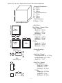
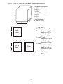
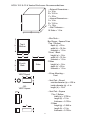
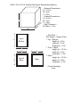
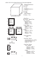
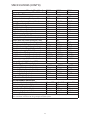
subwoofer
HCCA
10.2
12.2
15.2
10.4
12.4
15.4
TABLE OF CONTENTS
Introduction . . . . . . . . . . . . . . . . . . . . . . . . . . . . . . . . . . . . . . . . . . . . . . . . . . . . . . . . . . . . . . . . . . .3
Practice Safe Sound™ . . . . . . . . . . . . . . . . . . . . . . . . . . . . . . . . . . . . . . . . . . . . . . . . . . . . . . . . . . .3
Installation . . . . . . . . . . . . . . . . . . . . . . . . . . . . . . . . . . . . . . . . . . . . . . . . . . . . . . . . . . . . . . . . . . . .3
Tools of the Trade . . . . . . . . . . . . . . . . . . . . . . . . . . . . . . . . . . . . . . . . . . . . . . . . . . . . . . . . . . . . . .4
Finding Speaker Mounting Locations . . . . . . . . . . . . . . . . . . . . . . . . . . . . . . . . . . . . . . . . . . . . . .4
Features . . . . . . . . . . . . . . . . . . . . . . . . . . . . . . . . . . . . . . . . . . . . . . . . . . . . . . . . . . . . . . . . . . . . . .4
Re-cone Kit . . . . . . . . . . . . . . . . . . . . . . . . . . . . . . . . . . . . . . . . . . . . . . . . . . . . . . . . . . . . . . . . . . . .6
Wiring Configurations . . . . . . . . . . . . . . . . . . . . . . . . . . . . . . . . . . . . . . . . . . . . . . . . . . . . . . . . . .6
Parallel—One Speaker (dual 2 ohm voice coils) . . . . . . . . . . . . . . . . . . . . . . . . . . . . . . . . . . .7
Parallel—Two Speakers (dual 4 ohm voice coils) . . . . . . . . . . . . . . . . . . . . . . . . . . . . . . . . . .8
Parallel—One Speaker (dual 4 ohm voice coils) . . . . . . . . . . . . . . . . . . . . . . . . . . . . . . . . . . .9
Series-Parallel—Two Speakers (dual 2 ohm voice coils) . . . . . . . . . . . . . . . . . . . . . . . . . . . .10
Series-Parallel—Three Speakers (dual 4 ohm voice coils) . . . . . . . . . . . . . . . . . . . . . . . . . . .11
Series—One Speaker (dual 2 ohm voice coils) . . . . . . . . . . . . . . . . . . . . . . . . . . . . . . . . . . .12
Series-Parallel—Four Speakers (dual 4 ohm voice coils) . . . . . . . . . . . . . . . . . . . . . . . . . . . .13
Series-Parallel—Four Speakers (dual 2 ohm voice coils) . . . . . . . . . . . . . . . . . . . . . . . . . . . .14
2 Amplifiers—One Speaker (dual 2 ohm voice coils) . . . . . . . . . . . . . . . . . . . . . . . . . . . . . .15
2 Amplifiers—One Speaker (dual 4 ohm voice coils) . . . . . . . . . . . . . . . . . . . . . . . . . . . . . .16
Enclosure Design . . . . . . . . . . . . . . . . . . . . . . . . . . . . . . . . . . . . . . . . . . . . . . . . . . . . . . . . . . . . . .17
HCCA 10.2 & 10.4 Sealed Enclosure Recommendations . . . . . . . . . . . . . . . . . . . . . . . . . . . .18
HCCA 10.2 & 10.4 Vented Enclosure Recommendations . . . . . . . . . . . . . . . . . . . . . . . . . . .19
HCCA 12.2 & 12.4 Sealed Enclosure Recommendations . . . . . . . . . . . . . . . . . . . . . . . . . . . .20
HCCA 12.2 & 12.4 Vented Enclosure Recommendations . . . . . . . . . . . . . . . . . . . . . . . . . . .21
HCCA 15.2 & 15.4 Sealed Enclosure Recommendations . . . . . . . . . . . . . . . . . . . . . . . . . . . .22
HCCA 15.2 & 15.4 Vented Enclosure Recommendations . . . . . . . . . . . . . . . . . . . . . . . . . . .23
Specifications . . . . . . . . . . . . . . . . . . . . . . . . . . . . . . . . . . . . . . . . . . . . . . . . . . . . . . . . . . . . . . . . .24
Specifications (Cont’d) . . . . . . . . . . . . . . . . . . . . . . . . . . . . . . . . . . . . . . . . . . . . . . . . . . . . . . . . .25
2
INTRODUCTION
Thank you for your purchase of the Orion HCCA SubWoofers. These woofers
represent a combination of incredible performance and value. The HCCA series
subwoofers feature a massive 4" voice coil and triple stacked magnet assembly to
maximize excursion and output. Capable of maintaining their balance at
exceptionally high output levels. These high-performance woofers are built with dual
2 or 4 ohm voice coils, to get the most out of your amplifier. They are available in
standard 10”, 12” and 15” sizes.
We at Orion strive to give you all the latest up to date information about this product.
What we can’t give you in this manual is personal installation or technical experience.
If you have questions concerning the use or application of this product, please refer
to the nearest Authorized ORION Dealer for assistance, visit www.orioncaraudio.com,
or call the Orion technical support hotline at 1-800-876-0800. As we are always
finding new ways to improve our product, the features and specifications are subject
to change without notice.
PRACTICE SAFE SOUND™
Continuous exposure to sound pressure levels over 100dB may cause permanent
hearing loss. High powered automotive sound systems can generate sound pressure
levels in excess of 130dB. When playing your system at high levels, please use hearing
protection and prevent long term exposure.
INSTALLATION
The performance of these HCCA subwoofers is directly proportional to the quality of
installation. Care taken during the installation process will be rewarded with years of
satisfying performance. If you are unsure about your installation capabilities, please
refer to your local Authorized Orion Dealer for technical assistance. Orion dealers are
trained professionals dedicated to extracting the maximum performance out of your
Orion system. If you decide to install this speaker system yourself, please read the
entire section on sealed and vented enclosures before starting your installation.
Please Note: Due to the extremely long excursion and high temperature possibilities
of this woofer, it is recommended that when the woofer is installed it be positioned
so that the cone either faces upward or downward only.
3
TOOLS OF THE TRADE
Listed are the majority of the tools required to perform the installation. Having
proper tools will make the installation much easier. It is very difficult when you
half way through the installation and discover that you require a specific tool to
yourself through a particular part of the installation. Some of these tools
necessities. Some make the job much easier.
• Marking Pen
• Electric Drill
• Assorted Drill Bits
• Phillips Screwdriver
• Allen wrenches
• Volt/Ohm Meter (Optional)
• Wire Strippers
• Wire Cutters
• Table saw
• Wire Crimper
• Jig saw
the
get
get
are
FINDING SPEAKER MOUNTING LOCATIONS
Choosing the correct speaker locations will have the greatest effect on the sound
quality of the system. There are many different considerations needed when choosing
the locations that best suit your needs. The locations must be large enough for the
speakers to fit. Care is needed to ensure that the location you have chosen will not
affect any of the mechanical or electrical operations of the vehicle.
Determining the best location for the speakers will depend on your cosmetic needs
and your vehicle's interior. Usually the woofers are installed in the trunk, rear seat, or
rear of the vehicle.
FEATURES
1
2
21
20
19
18
17
16
15
3
4
5
6
7
8
9
14
10
13
12
11
4
1.
Paper dust cap - moisture and UV 12. Voice coil gap vents. Part of the
resistant.
enhanced voice coil cooling system
(forced convection - aluminum heat
sinking -shorting rings to reduce
inductive heating).
2.
Tall, wide, balanced, NBR Foam (high 13. Cast aluminum rear pole piece heat
density expanded polyester foam)
sink with fins and vent holes. Part of
surround for linear controlled long
the enhanced voice coil cooling
excursion using a Tri Radius
system
(forced
convection
symmetrical edge design optimized
aluminum heat sinking).
on non-linear FEA.
Paper cone - moisture and UV 14. High temperature (Polyester Amide
resistant.
Amide Resin Coated) Copper clad
Aluminum voice coil wound on an
aluminum former (10" uses 3" voice
coil, 12 & 15 use a 4" voice coil) Dual
2 and 4 ohm voice coils available.
Custom Cast Aluminum frame.
15. Screen meshed areas to allow
venting below spider to and keep
foreign object out of the voice coil gap.
3.
4.
5.
6.
7.
Spider ring attachment screws. Part 16. Cast aluminum top pole piece heat
of re-cone feature (8 hex screws).
sink with fins and vent hole. Part of
the enhanced voice coil cooling
system (forced convection-aluminum
heat sinking-shorting rings to reduce
inductive heating).
aluminum voice coil former (10" uses 17. Bottom flat interlaced Conex spider
3" voice coil former, 12 & 15 use a 4"
with stitched and looped tinsel leads
voice coil former).
attached.
Venting in Voice coil former. Part of 18. Custom allen head screw terminals.
the enhanced voice coil cooling
A pair on each side (one pair for
system (forced convection).
each voice coil).
8.
11mm Steel front plate.
19. Spider spacer and spider mounting
ring assembly part of field re-cone
kit attachment method. (eight allen
head screws).
9.
Large 3 stack ceramic magnets (10" 20. Top flat interlaced Conex spider.
264 oz 12/15" 445 oz).
10. 11mm Steel back plate / pole piece 21. Surround clamp ring, part of field reT yoke assembly.
cone kit attachment method. (eight
allen head screws).
11. 1.25" vent. Part of the enhanced
voice coil cooling system (forced
convection - aluminum heat sinking shorting rings to reduce inductive
heating).
5
RE-CONE KIT
A re-cone kit is available for these speakers and can be obtained from your dealer. The
part number for each model is listed below.
Model
HCCA10.2CK
HCCA10.4CK
HCCA12.2CK
HCCA12.4CK
HCCA15.2CK
HCCA15.4CK
Description
ORION HCCA
ORION HCCA
ORION HCCA
ORION HCCA
ORION HCCA
ORION HCCA
10"
10"
12"
12"
15"
15"
2
4
2
4
2
4
OHM
OHM
OHM
OHM
OHM
OHM
Re-Cone
Re-Cone
Re-Cone
Re-Cone
Re-Cone
Re-Cone
Kit
Kit
Kit
Kit
Kit
Kit
Re-cone Kit p/n
27902
27904
27907
27909
27912
27914
WIRING CONFIGURATIONS
The following illustrations provide guidelines on properly connecting your HCCA
Orion woofer to an Orion amplifier for maximum power and performance using
common parallel, and series/parallel wiring configurations.
Recommended Amplifier Power
1 woofer
1,200 to 4,000 watts
2 woofers
2,400 to 8,000 watts
3 woofers
3,600 to 12,000 watts
4 woofers
4,800 to 16,000 watts
6
Parallel—One Speaker (dual 2 ohm voice coils)
One dual 2 ohm voice coil woofer with voice coils in parallel results in a 1 ohm load
to the amplifier.
2 ohm
-
2 ohm
-
+
+
+
-
1. Connect the speaker in parallel by connecting the two positive (+) terminals
together and the two negative (-) terminals together.
2. Wire the positive (+) terminals of the woofer to the positive (+) terminal on the
amplifier. Wire the negative (-) terminals of the woofer to the negative (-) terminal
on the amp
7
Parallel—Two Speakers (dual 4 ohm voice coils)
Two dual 4 ohm voice coil woofers with voice coils in parallel and the two woofers in
parallel results in a 1 ohm load to the amplifier.
+
+
+
4 ohm
-
4 ohm
4 ohm
-
4 ohm
-
+
+
-
1. Connect the speaker in parallel by connecting the four positive (+) terminals
together and the four negative (-) terminals together.
2. Wire the positive (+) terminals of the woofers to the positive (+) terminal on the
amplifier. Wire the negative (-) terminals of the woofers to the negative (-) terminal
on the amplifier.
8
Parallel—One Speaker (dual 4 ohm voice coils)
One dual 4 ohm voice coil woofer with voice coils in parallel results in a 2 ohm load
to the amplifier.
+
+
4 ohm
-
4 ohm
-
+
-
1. Connect the speaker in parallel by connecting the two positive (+) terminals
together and the two negative (-) terminals together.
2. Wire both positive (+) terminals of the woofer to the positive (+) terminal on the
amplifier. Wire both negative (-) terminals of the woofer to the negative (-) terminal
on the amplifier.
9
Series-Parallel—Two Speakers (dual 2 ohm voice coils)
Note: Verify and ensure that the woofer wiring is connected as shown with
the negative connection from the first woofer coil connected to the positive
connection of the second woofer coil.
Two dual 2 ohm voice coil woofers with voice coils in series and then parallel the two
series woofers results in a 2 ohm load to the amplifier.
+
+
2 ohm
2 ohm
+
-
2 ohm
-
-
2 ohm
-
+
+
-
1. Connect each woofer in series by connecting the negative (-) of the first coil to the
positive (+) terminal of the second coil.
2. Wire the positive (+) terminal of the first coil on each woofer to the positive (+)
terminal on the amplifier. Wire the negative (-) terminal of the second coil on each
woofer to the negative (-) terminal on the amplifier.
10
Series-Parallel—Three Speakers (dual 4 ohm voice coils)
Note: Verify and ensure that the woofer wiring is connected as shown with
the negative connection from the first woofer coil connected to the positive
connection of the second woofer coil.
Three dual 4 ohm voice coil woofer with voice coils of each woofer wired in series and
then parallel the three woofers for a resulting 2.67 ohms.load to the amplifier.
+
+
+
4 ohm
4 ohm
-
+
+
4 ohm
-
-
4 ohm
-
4 ohm
-
4 ohm
-
+
+
-
1. Connect each woofer in series by connecting the negative (-) of the first coil to the
positive (+) terminal of the second coil.
2. Wire the positive (+) terminal of each woofer’s first coil to the positive (+) terminal
on the amplifier. Wire the negative (-) terminal of each woofer’s second coil to the
negative (-) terminal on the
amplifier.
11
Series—One Speaker (dual 2 ohm voice coils)
One dual 2 ohm voice coil woofer with voice coils in connected in series results in a 4
ohm load to the amplifier.
+
2 ohm
-
2 ohm
-
+
+
-
1. Connect the woofer in series by connecting the negative (-) of one terminal to the
positive (+) terminal of the other coil.
2. Wire the positive (+) terminal of the first coil to the positive (+) terminal on the
amplifier. Wire the negative (-) terminal of the second coil to the negative (-) terminal
on the amplifier.
12
Series-Parallel—Four Speakers (dual 4 ohm voice coils)
Note: Verify and ensure that the woofer wiring is connected as shown with
the negative connection from the first woofer coil connected to the positive
connection of the second woofer coil.
Four dual 4 ohm voice coil woofers should be wired with the voice coils on each
woofer in series and then parallel the four woofers for a resulting 2 ohm load to the
amplifier.
+
+
+
+
+
+
4 ohm
-
4 ohm
-
4 ohm
-
4 ohm
-
4 ohm
-
4 ohm
-
4 ohm
-
4 ohm
-
+
+
+
-
1. Connect each woofer in series by connecting the negative (-) of the first coil to the
positive (+) terminal of the second coil.
2. Wire the positive (+) terminals of the first coil of each woofer to the positive (+)
terminal on the amplifier. Wire the negative (-) terminal of the second coil of each
woofer to the negative (-) terminal on the amplifier.
13
Series-Parallel—Four Speakers (dual 2 ohm voice coils)
Note: Verify and ensure that the woofer wiring is connected as shown with
the negative connection from the first woofer coil connected to the positive
connection of the second woofer coil.
Four dual 2 ohm voice coil woofers should be wired with the voice coils on each
woofer in series and then parallel the four woofers for a resulting 1 ohm load to the
amplifier.
+
+
+
+
+
+
2 ohm
-
2 ohm
-
2 ohm
-
2 ohm
-
2 ohm
-
2 ohm
-
2 ohm
-
2 ohm
-
+
+
+
-
1. Connect each woofer in series by connecting the negative (-) of the first coil to the
positive (+) terminal of the second coil.
2. Wire the positive (+) terminals of the first coil of each woofer to the positive (+)
terminal on the amplifier. Wire the negative (-) terminal of the second coil of each
woofer to the negative (-) terminal on the amplifier.
14
2 Amplifiers—One Speaker (dual 2 ohm voice coils)
One dual 2 ohm voice coil woofer with each voice coil connected to an individual
amplifier, resulting in a 2 ohm load to each amplifier.
-
+
+
2 ohm
2 ohm
-
+
+
-
-
1. Connect one of the speaker’s voice coils to the first amplifier by connecting the
positive (+) terminal and the negative (-) terminal from the speaker to the respective
positive (+) terminal and the negative (-) terminal from the first amplifier.
2. Connect the other of the speaker’s voice coils to the second amplifier by connecting
the positive (+) terminal and negative (-) terminal from the speaker to the respective
positive (+) terminal and the negative (-) terminal from second amplifier.
15
2 Amplifiers—One Speaker (dual 4 ohm voice coils)
One dual 4 ohm voice coil woofer with each voice coil connected to an individual
amplifier, resulting in a 4 ohm load to each amplifier.
-
+
+
4 ohm
4 ohm
-
+
+
-
-
1. Connect one of the speaker’s voice coils to the first amplifier by connecting the
positive (+) terminal and the negative (-) terminal from the speaker to the respective
positive (+) terminal and the negative (-) terminal from the first amplifier.
2. Connect the other of the speaker’s voice coils to the second amplifier by connecting
the positive (+) terminal and negative (-) terminal from the speaker to the respective
positive (+) terminal and the negative (-) terminal from second amplifier.
16
ENCLOSURE DESIGN
This section gives the basic description for a sealed enclosure. Orion HCCA woofers
are designed for sealed enclosures and vented enclosures. Sealed enclosures are
generally considered the most versatile for all music types and are the easiest to
build. They will also give high power handling with a wider range of frequencies.
The enclosure must be absolutely air tight. Use a high quality wood glue for all
seams of the enclosure. The enclosure should also be screwed together. The
enclosure should be no less than 3/4" on sides. The baffle board (woofer mounting
plate) should be no less than 1". If the woofer mounting is to be recessed then a
minimum of two 3/4" plates together should be used. As MDF is a porous material
it is best to also seal the inside of the enclosure.
NOTE: The woofer must face up or down only, especially in sealed enclosures.
NOTE: Refer to the website www.orioncaraudio.com for updated enclosure
data for your woofer application.
17
HCCA 10.2 & 10.4 Sealed Enclosure Recommendations
A
C
—External Dimensions—
A = 13 in.
B = 13.5 in.
C = 14.5 in.
—Internal Dimensions—
A = 11 in.
B = 11.5 in.
C = 12.5 in.
—Wall Thickness—
All Sides = 1.0 in.
B
c
—Box Parts—
Box Shape – Square Prism
1 Top, 1 Bottom
depth (c) = 14.5 in.
width (b) = 13.5 in.
thickness = 1.0 in.
1 Front, 1 Back
height (a) = 11 in.
width (d) = 11.5 in.
thickness = 1.0 in.
2 Sides
height (a) = 11 in.
depth (c) = 14.5 in.
thickness = 1.0 in.
Top &
Bottom
b
a
d
c
Front &
Back
Sides
—Driver Mounting—
Front
18
HCCA 10.2 & 10.4 Vented Enclosure Recommendations
A
C
—External Dimensions—
A = 13.5 in.
B = 14.5 in.
C = 15.5 in.
—Internal Dimensions—
A = 11.5 in.
B = 12.5 in.
C = 13.5 in.
—Wall Thickness—
All Sides = 1.0 in.
B
—Box Parts—
Box Shape – Square Prism
1 Top, 1 Bottom
depth (c) = 15.5 in.
width (b) = 14.5 in.
thickness = 1.0 in.
1 Front, 1 Back
height (a) = 11.5 in.
width (d) = 12.5 in.
thickness = 1.0 in.
2 Sides
height (a) = 11.5 in.
depth (c) = 15.5 in.
thickness = 1.0 in.
Top &
Bottom
c
b
a
d
c
Front &
Back
Sides
—Driver Mounting—
Front
VENT Round
h
e
g
—Vent Part—Round
outside diameter (e) = 2.75 in.
inside diameter (g) = 2.5 in.
length (h) = 10 in.
- OR VENT Square
e
—Vent Part—Square
1 Top, 1 Bottom
width (e) = 2.466 in.
length (h) = 10 in.
thickness = 0.125 in.
2 Sides
height (g) = 2.216 in.
length (h) = 10 in.
thickness = 0.125 in.
h
h
g
19
HCCA 12.2 & 12.4 Sealed Enclosure Recommendations
A
C
—External Dimensions—
A = 16.5 in.
B = 16 in.
C = 16 in.
—Internal Dimensions—
A = 14 in.
B = 14 in.
C = 14 in.
—Wall Thickness—
All Sides = 1.0 in.
B
c
—Box Parts—
Box Shape – Square Prism
1 Top, 1 Bottom
depth (c) = 16 in.
width (b) = 16 in.
thickness = 1.0 in.
1 Front, 1 Back
height (a) = 14.5 in.
width (d) = 14 in.
thickness = 14 in.
2 Sides
height (a) = 14.5 in.
depth (c) = 16 in.
thickness = 1.0 in.
Top &
Bottom
b
a
d
c
Front &
Back
Sides
—Driver Mounting—
Front
20
HCCA 12.2 & 12.4 Vented Enclosure Recommendations
A
C
—External Dimensions—
A = 16 in.
B = 15.5 in.
C = 20 in.
—Internal Dimensions—
A = 14 in.
B = 13.5 in.
C = 18 in.
—Wall Thickness—
All Sides = 1.0 in.
B
—Box Parts—
Box Shape – Square Prism
1 Top, 1 Bottom
depth (c) = 20 in.
width (b) = 15.5 in.
thickness = 1.0 in.
1 Front, 1 Back
height (a) = 14 in.
width (d) = 13.5 in.
thickness = 1.0 in.
2 Sides
height (a) = 14 in.
depth (c) = 20 in.
thickness = 1.0 in.
Top &
Bottom
c
b
a
d
c
Front &
Back
Sides
—Driver Mounting—
Front
VENT Round
h
e
g
—Vent Part—Round
outside diameter (e) = 4.25 in.
inside diameter (g) = 4 in.
length (h) = 15 in.
- OR VENT Square
e
—Vent Part—Square
1 Top, 1 Bottom
width (e) = 3.795 in.
length (h) = 15 in.
thickness = 0.125 in.
2 Sides
height (g) = 3.545 in.
length (h) = 15 in.
thickness = 0.125 in.
h
h
g
21
HCCA 15.2 & 15.4 Sealed Enclosure Recommendations
A
C
—External Dimensions—
A = 17.5 in.
B = 18 in.
C = 20 in.
—Internal Dimensions—
A = 15.5 in.
B = 16 in.
C = 18 in.
—Wall Thickness—
All Sides = 1.0 in.
B
c
—Box Parts—
Box Shape – Square Prism
1 Top, 1 Bottom
depth (c) = 20 in.
width (b) = 18 in.
thickness = 1.0 in.
1 Front, 1 Back
height (a) = 15.5 in
width (d) = 19 in.
thickness = 1.0 in.
2 Sides
height (a) = 15.5 in
depth (c) = 20 in.
thickness = 1.0 in.
Top &
Bottom
b
a
d
c
Front &
Back
Sides
—Driver Mounting—
Front
22
HCCA 15.2 & 15.4 Vented Enclosure Recommendations
A
C
—External Dimensions—
A = 17.5 in.
B = 21 in.
C = 18 in.
—Internal Dimensions—
A = 15.5 in.
B = 19 in.
C = 16 in.
—Wall Thickness—
All Sides = 1.0 in.
B
—Box Parts—
Box Shape – Square Prism
1 Top, 1 Bottom
depth (c) = 18 in.
width (b) = 21 in.
thickness = 1.0 in.
1 Front, 1 Back
height (a) = 15.5 in.
width (d) = 19 in.
thickness = 1.0 in.
2 Sides
height (a) = 15.5 in.
depth (c) = 18 in.
thickness = 1.0 in.
Top &
Bottom
c
b
a
d
c
Front &
Back
Sides
—Driver Mounting—
Front
VENT Round
h
e
g
—Vent Part—Round
outside diameter (e) = 5.25 in.
inside diameter (g) = 5 in.
length (h) = 15 in.
- OR VENT Square
e
—Vent Part—Square
1 Top, 1 Bottom
width (e) = 4.681 in.
length (h) = 15 in.
thickness = 0.125 in.
2 Sides
height (g) = 4.431 in.
length (h) = 15 in.
thickness = 0.125 in.
h
h
g
23
SPECIFICATIONS
Directed Part Number 27302
Model Number 10.2
Thiele/Small Parameters
Fs (free-air resonance, Hz)
30.78
Vas (equivalent compliance, cu. ft.
0.564
Vas (equivalent compliance, liters)
15.98
Qms (Q, mechanical)
3.63
Qes (Q, electrical)
0.42
Qts (total driver Q)
0.38
Re (DC resistance, ohms)
3.93
Z (nominal impedance, ohms)
2x2
Le (inductance, mh)
1.93
Efficiency (1W @ 1M, dB)
83
Xmax (one way linear excursion, in.)
1.0
Xmax (one way linear excursion, mm)
25
Pe (continuous power handling, watts)
1500
Peak power handling (music, watts)**
3000
Mms (total moving mass, grams)
261.93
Cms (mechanical compliance, mm/N)
0.102
Bl (motor strength, Tesla-M)
21.81
Sd (effective radiating area, sq. cm.)
333.3
Sd (effective radiating area, sq. m.)
0.03333
Sd (effective radiating area, sq. in.)
51.6616
Frequency range (Hz)
31-250
Energy Bandwidth Product (EBP)
74
Driver Physical Dimension
Speaker Displacement (cu ft.)
0.1268
Mounting hole diameter (mm)
238
Mounting hole diameter (inches)
9.37
Mounting depth (mm)
214
Mounting depth (inches)
8.425
Magnet Weight (Oz)
263.7
Basket diameter (inches)
Recommended Enclosures
Typical sealed enclosure (cu. ft.)
0.5 to 0.8
Vented enclosure (cu. ft.)
1.2
Port tuning frequency (Hz)
38
Port diameter (inside, in.)
3.4
Equivalent square port (in.)
3x3
Port length (in.)
12
Enclosure Details
27304
10.4
27307
12.2
32.49
0.564
15.98
3.63
0.46
0.41
7.57
2x4
2.93
83
1.0
25
1500
3000
235.64
0.102
28.05
333.3
0.03333
51.6616
32-250
70
22.56
1.847
52.33
2.99
0.36
0.32
4.07
2x2
2.61
85
1.2
30
2000
4000
421.18
0.118
25.85
559.9
0.05599
86.78467
23-250
62
0.15382
238
9.37
214
8.425
263.7
0.28931
292
11.496
261
10.276
445
0.5 to 0.8
1.2
38
3.4
3x3
12
0.9 to 1.35
2
38
5
4.5x4.5
15
1. Parameters listed are for conventional applications only, for further help please call Tech Audio Support
2. 1" MDF is recommended.
3. Recommended enclosures are NET Box Volumes, speaker and port displacement are calculated into the
volume of the enclosure, you will not need to add these volumes to calculate GROSS volume for the
enclosure.
*** Sub-sonic filters should always be used and adjusted specifically for vented box designs.
NOTE: The woofer must face up or down only, especially in sealed enclosures.
Specifications subject to change without notice
© 2007 Directed Electronics, Inc. Vista, CA 92081 All rights reserved.
24
SPECIFICATIONS (CONT’D)
Directed Part Number 27309
Model Number 12.4
Thiele/Small Parameters
Fs (free-air resonance, Hz)
23.98
Vas (equivalent compliance, cu. ft.
1.847
Vas (equivalent compliance, liters)
52.33
Qms (Q, mechanical)
2.99
Qes (Q, electrical)
0.42
Qts (total driver Q)
0.37
Re (DC resistance, ohms)
7.76
Z (nominal impedance, ohms)
2x4
Le (inductance, mh)
3.67
Efficiency (1W @ 1M, dB)
85
Xmax (one way linear excursion, in.)
1.2
Xmax (one way linear excursion, mm)
30
Pe (continuous power handling, watts)
2000
Peak power handling (music, watts)**
4000
Mms (total moving mass, grams)
372.77
Cms (mechanical compliance, mm/N)
0.118
Bl (motor strength, Tesla-M)
32.07
Sd (effective radiating area, sq. cm.)
559.9
Sd (effective radiating area, sq. m.)
0.05599
Sd (effective radiating area, sq. in.)
86.78467
Frequency range (Hz)
24-250
Energy Bandwidth Product (EBP)
57
Driver Physical Dimension
Speaker Displacement (cu ft.)
0.30361
Mounting hole diameter (mm)
292
Mounting hole diameter (inches)
11.496
Mounting depth (mm)
261
Mounting depth (inches)
10.276
Magnet Weight (Oz)
445
Basket diameter (inches)
Recommended Enclosures
Typical sealed enclosure (cu. ft.)
0.9 to 1.35
Vented enclosure (cu. ft.)
2
Port tuning frequency (Hz)
35
Port diameter (inside, in.)
5
Equivalent square port (in.)
4.5x4.5
Port length (in.)
15
27312
15.2
27314
15.4
23.72
4.01
113.68
2.99
0.46
0.40
4.08
2x2
2.59
88
1.2
30
2000
4000
517.86
0.087
26.03
962.1
0.09621
149.1258
24-250
51
24.73
7.23
113.68
2.99
0.52
0.44
7.23
2x4
3.68
88
1.2
30
2000
4000
476.42
0.087
32.15
962.1
0.09621
149.1258
24-250
48
0.37704
383
15.079
294
11.575
445
0.33403
383
15.079
294
11.575
445
1.9 to 2.5
3.5
35
6.25
5.5x5.5
14.5
1.9 to 2.5
3.5
35
6.25
5.5x5.5
14.5
NOTE: Due to the high power capabilities and long excursion of these woofers, the Thiele/Small Parameters
were calculated and measured using a Klippel analyzer system.
25
NO WARRANTY
THIS PRODUCT IS SOLD "AS-IS"
DIRECTED ELECTRONICS (hereinafter "SELLER") MAKES NO WARRANTY of any kind
(express, implied or otherwise) in connection with this Product. THIS PRODUCT IS SOLD
AS-IS, AND YOU THE PURCHASER ASSUME THE ENTIRE RISK AS TO ITS QUALITY AND
PERFORMANCE. ANY IMPLIED WARRANTY OF MERCHANTABILITY OR FITNESS FOR A
PARTICULAR PURPOSE THAT EXCEEDS THE FOREGOING WARRANTY IS HEREBY
EXPRESSLY DISCLAIMED BY SELLER TO THE MAXIMUM EXTENT ALLOWED BY LAW
AND IS EXCLUDED FROM ANY AGREEMENT MADE BY ACCEPTING THIS OFFER.
SELLER neither assumes nor authorizes any person to assume for it any liability in
connection with the sale of this Product. SELLER has absolutely no liability for any and all
acts of third parties including distributors, authorized dealers or installers. SELLER will not
be liable for any direct, indirect, special, incidental or consequential damages, loss or
expense arising in connection with the use of the Product or the inability to use the Product
for any purpose whatsoever. This Product is not eligible for return or exchange. Any return
of this Product to SELLER will be declined at Shipper's expense.
All exclusions and limitation are made only to the extent permitted by applicable law and
shall be of no effect to the extent in conflict with the express requirements of applicable
law. Some states do not allow the exclusion or limitation of incidental or consequential
damages. In such states, the exclusion or limitations stated herein may not apply to you.
You may have specific legal or other rights which vary from state to state.
p/n 920-0034 01-07
For more information on Orion products please visit us at www.orioncaraudio.com
© 2007 Directed Electronics, All rights reserved. G27302.04.07.09.12.14 03-07