1
User’s Manual
OPT-6125 Series
Handheld CCD Scanner
25-ULGPMU01-01
April 2002
Keyboard Wedge Interface
USB Interface
RS232 Interface
8 Olympic Drive
Orangeburg, NY 10962
Tel 845.365.0090
Fax 845.365.1251
www.opticonUSA.com
Manual No. 25-ULGPMU01-01
Series OPT Handheld CCD Scanner
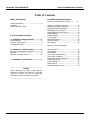
Table of Contents
PART I CCD Scanning
General Information ...........................................4
Unpacking
Factory Technical Support
Part II Installation and SetUp
A. Installation –Wedge Interface ……………5
Reset all Defaults …………………………………………….6
Computer Type Selection … ............................... 6
InterCharacter Delay ..........................................7
Part III Bar Code Menu Functions
Section A Programming the Scanner……………..12
Section B Symbology Selections ..................... 13
Enabling only a single symbology ...................... 13
Enabling an addition symbology........................ 13
Setting Options for UPC-A/E ............................. 17
Setting Options for EAN-13 and -8 .................... 20
Code 39 Settings ............................................. 22
Codabar Settings ............................................. 24
2 of 5 Settings................................................. 27
MSI/Plessey Setting ......................................... 29
Code 128 Setting ............................................. 30
IATA Settings .................................................. 31
Section C: Universal Selections
B. Installation – RS232 Interface................ 8
RS-232C Communication Parameters ..................9
Baud Rate..........................................................9
Data Bits / Stop Bits / Parity..............................10
C. Installation – USB Interface...................11
_________________________________________
NOTICE
Opticon has taken every step to ensure that the
information included in this manual is accurate,
however we reserve the right to change any
specification at any time without prior notice.
_________________________________________
Case Conversion .............................................. 33
Prefix Options.................................................. 34
Suffix Options.................................................. 36
Direct Input - Keyboard Keys ............................ 38
Direct Input - Characters ................................ 44
Direct Input - Control Characters ...................... 49
Read Mode Settings ......................................... 52
Trigger Settings ............................................... 53
Beeper Options................................................ 57
Good Read Indicator (LED)............................... 59
Page 3
Manual No. 25-ULGPMU01-01
Series OPT Handheld CCD Scanner
Part I
General Information
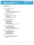
The OPT-6125 Series CCD Scanners utilize state-of-the-art imaging technology similar to that found in digital cameras,
facsimile machines and video camcorders. The scanner images the bar code label, then converts the digital signals into data
the host computer can understand. By capturing the bar code image all at once, the scanner provides fast, highly accurate
reading.
Miniature surface mount electronics make up the CCD scanner's solid state construction. CCD scanners have no moving
mechanical parts and provide years of trouble-free operation.
This manual contains information on setting-up the scanner as well as programming various parameters of the scanner.
The OPT6125 scanner is available in several different interface configurations:
Keyboard Wedge Interface
RS232 Serial Interface
USB Interface
There is a specific section of this manual for installing each type of interface. Be sure you are using the section of the
manual that pertains to interface you are using.
Unpacking
Remove the scanner from its packaging and inspect it for damage. If the scanner was damaged in transit, call the dealer or
distributor from whom you purchased it. If you purchased it directly from Opticon, call Opticon Customer Service Dept. at
800-636-0090.
Factory Technical Support
If you have any questions or need assistance with programming your scanner call Opticon Technical Support at 800-6360090 please have the unit model number and several bar code labels readily at hand. The model number is located near the
connector end of the cable.
If the scanner must be returned, please contact Opticon to obtain an RMA (Return Merchandise Authorization) number prior
to returning the product. The Customer Service Dept. may be reached at 800-636-0090.
NOTE: Returned merchandise will not be accepted without a RMA number indicated clearly on the outside of the carton.
Page 4
Manual No. 25-ULGPMU01-01
Series OPT Handheld CCD Scanner
Part II Installation and SetUp
This section of the manual contains information on the physical installation of the scanner as well as certain programming options.
There is a separate section for each type of interface. Check to see which type of interface your scanner has and turn to that
section for information on installing the scanner
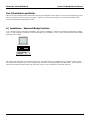
A.) Installation – Keyboard Wedge Interface
A "Y" connection cable is required for installation. The scanner is installed or "wedged" between the keyboard and the computer..
Your “Y” cable should have connectors for both a PS2 and AT type installation. The "Y" cable connects both the scanner and the
keyboard to the computer.
The scanner must match the type of computer being used. The default setting is for an IBM AT type computer. If this type does
not match the host computer, refer to the “Computer Type Selection” in the programming section that follows. If the connector
does not match the host compute remove the short cable section, reverse it and insert it in the other connector
Page 5
Manual No. 25-ULGPMU01-01
Series OPT Handheld CCD Scanner
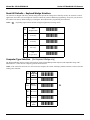
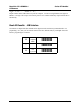
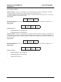
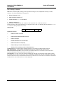
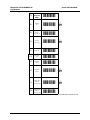
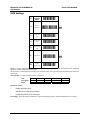
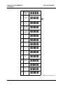
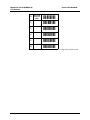
Reset All Defaults – Keyboad Wedge Interface
Our scanners are shipped with factory default settings that represent the settings most commonly used by our customers. In most
applications, the scanner will work right out of the box without any need for additional programming. At any time you can return
the scanner to the factory default settings by scanning the “Reset all Defaults” programming bar code below.
Β
NOTE: (
) A pointing finger indicates default settings throughout the following menus.
ZZ
Start
Program Menu
-[[-
UA
XT Wedge
-VB-
UB
AT Wedge
-VC-
UC
PS2 wedge
-VD-
ZZ
End
Program Menu
-[[-
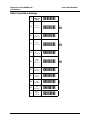
Computer Type Selection (for Keyboard Wedge only)
The Keyboard Wedge interface scanner is designed to operate with an IBM personal computers and compatibles along with a
Macintosh PC's. Select the host computer type from the menu below.
NOTE: If the scanner has not been set to the correct host computer, the scanner will display random characters on the screen after
reading a bar code label.
ZZ
Start
Program
Menu
-[[-
K0
IBM PC/XT
-L1-
K1
IBM AT &
compatibles
K3
HP Vectra
-L!-
K4
Macintosh
-L5-
ZZ
End
Program
Menu
-[[-
-L3-
Β
Page 6
Manual No. 25-ULGPMU01-01
Series OPT Handheld CCD Scanner
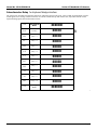
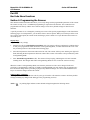
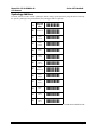
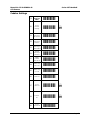
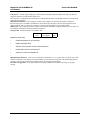
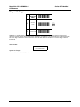
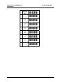
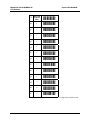
Intercharacter Delay for Keyboard Wedge interface
The scanner may send data faster than the computer or application program can accept. This is called "keyboard buffer overrun".
If data appears to be missing, random read errors occur or the scanner locks up and will not scan, experiment with the various
keyboard timing options listed in the menu to follow.
ZZ
Start Program
Menu
-[[-
LA
No Delay
-MB-
LB
Delay = 1
-MB-
LC
Delay = 2
-MD-
LD
Delay = 3
-ME-
LE
Delay = 4
-MF-
LF
Delay = 5
-MG-
LG
Delay = 6
-MH-
LH
Delay = 7
-MI-
LI
Delay = 8
-MJ-
LJ
Delay = 9
-MK-
LK
Delay = 10
-ML-
ZZ
End Program
Menu
-[[-
Β
+
Page 7
Manual No. 25-ULGPMU01-01
Series OPT Handheld CCD Scanner
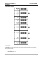
B.) Installation – RS232 Interface
The RS-232 scanner cable is terminated in with a DB9 female connector. An external power supply (+5V DC) may be necessary.
There is a power supply jack on the RS-232 connector.
Installation is as follows:
1. Plug the scanner into an RS232 serial port (such as COM1) of the host PC. If external power is required, insert external power
plug into the jack on the RS-232 connector.
2. Connect the power supply into an electrical outlet (110 V AC)
3. Turn on the power to the host computer. Make sure the communication parameters of the computer match those of the
scanner. The default communications settings are: 9600 baud, 8 data bits, 1 stop bit, no parity, no handshaking
4. Be sure the PC is in a program (such as WordPad) that will accept input from the serial port.
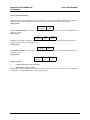
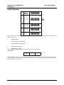
Reset All Defaults – RS232
Our scanners are shipped with factory default settings that represent the settings most commonly used by our customers. In most
applications, the scanner will work right out of the box without any need for additional programming. At any time you can return
the scanner to the factory default settings by scanning the “Reset all Defaults” programming bar code below.
ZZ
U2
ZZ
Start
Program Menu
-[[-
RS232
-V3-
End
Program Menu
-[[-
Page 8
Manual No. 25-ULGPMU01-01
Series OPT Handheld CCD Scanner
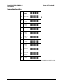
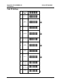
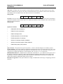
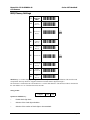
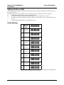
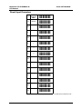
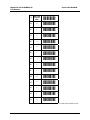
RS-232C Communication Parameters
Handshaking Protocol
ZZ
Start
Program
Menu
-[[-
P0
None
-Q1-
HP04
RTS/CTS
+IQ15+
P3
ACK/NAK
-Q!-
ZG
Xon/Xoff
-[H-
I0
I1
Flow
Control
Time
Unlimited
Flow
Control:
100ms
-J1-
Β
Β
-J2-
I2
Flow
Control:
200ms
-J3-
I3
Flow
Control:
400ms
-J!-
K7
19200
-L8-
K6
9600
-L7-
K5
4800
-L6-
K4
2400
-L5-
K3
1200
-L!-
K2
600
-L3-
Baud Rate
Β
Page 9
Manual No. 25-ULGPMU01-01
Series OPT Handheld CCD Scanner
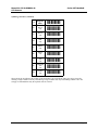
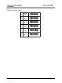
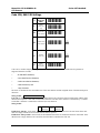
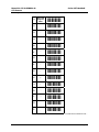
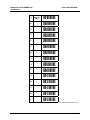
Data Bits / Stop Bits / Parity
L0
7 Data Bits
-M1-
L1
8 Data Bits
-M2-
L5
1 Stop Bit
-M6-
L6
2 Stop Bits
-M7-
L3
Even
Parity
-M!-
L4
Odd
Parity
-M5-
L2
Mark
No Parity
-M3-
ZZ
End
Program
Menu
,ZZ,
Β
Β
Β
Page 10
Manual No. 25-ULGPMU01-01
CCD Scanner
Series OPT Handheld
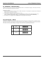
C.) Installation – USB Interface
Plug the scanner into the USB connector on your host computer. PC must be running Windows 98 or higher or
iMac Rev A or higher. The computer will sense the presence of the scanner and load any required software drivers
automatically.
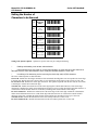
Reset All Defaults - USB Interface
Our scanners are shipped with factory default settings that represent the settings most commonly used by our
customers. In most applications, the scanner will work right out of the box without any need for additional
programming. At any time you can return the scanner to the factory default settings by scanning the “Reset all
Defaults” programming bar code below.
ZZ
Start
Program
Menu
-[[-
SU
USB
-TV-
ZZ
End
Program Menu
-[[-
Page 11
Manual No. 25-ULGPMU01-01
CCD Scanner
Series OPT Handheld
Part III
Bar Code Menu Functions
Section A Programming the Scanner
This manual contains information that allows you to easily change certain programmable parameters of the scanner.
The scanner is ready to use - no additional programming is required in most situations. The scanner has been
programmed at the factory with the most common settings. These factory default settings are ideal for most
situations.
A specific parameter is set or changed by scanning one or more of the special programming bar codes found on the
following pages. For each parameter, you can choose from a menu of options. When you scan the special bar code
for a specific menu option, the scanner retains the changes you have made even if you disconnect the scanner or turn off the power.
Step-by-Step
Programming is easy. Simply:
1.
Scan the bar code for "Start/End Program Menu" (ZZ). The scanner will beep continuously to indicate that it
is ready to be programmed. When the scanner is in Programming Mode, it cannot read normal bar code. It can
only read the special bar codes found on the following pages.
2.
Select desired parameter from menu and scan the bar code. The scanner will beep once and the green light will
flash, indicating the desired parameter has been scanned. The scanner will continue to beep continuously while
in Programming Mode.
3.
Scan "Start/End Program Menu" (ZZ). The scanner will stop beeping, indicating that it is back in normal
scanning mode. The changes made while in Programming Mode are now saved in the scanner's memory.
When the scanner is in Programming Mode, more than one parameter at a time can be changed. Until some
proficiency at programming is achieved, it is highly recommended that users only change only one parameter at a
time and test the change before proceeding to program any additional changes. It is also recommended that users
keep a record of the changes made to the scanner.
What If I Make A Mistake?
Scanning the "Reset All Defaults" bar code for your type of interface will return the scanner to all factory default
settings (including any changes made during previous programming sessions).
Β ) A pointing finger indicates scanner default settings throughout the following menus.
NOTE: (
Page 12
Manual No. 25-ULGPMU01-01
CCD Scanner
Series OPT Handheld
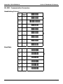
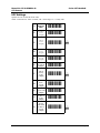
Symbology Selection
ZZ
Start/End
Program
Menu
A0
Read all codes
A2
Code 39
only
A3
Codabar
only
-B!-
A4
IATA only
-B5-
A5
Code 93
only
-B6-
A6
Code 128
only
-B7-
A7
MSI/Plessey
only
-B8-
A9
Telepen
only
-B:-
AB
Matrix 2of5
only
-BC-
J0
All UPC and
EAN only
-K1-
J1
UPC
only
-K2-
-[[-B1- Β
-B3-
CONTINUED ON NEXT PAGE...
Page 13
Manual No. 25-ULGPMU01-01
CCD Scanner
Series OPT Handheld
Symbology Selection (continued)
ZZ
Start/End
Program
Menu
-[[-
J2
UPC+2
only
-K3-
J3
UPC+5
only
-K!-
J4
EAN
only
-K5-
J5
EAN+2
only
-K6-
J6
EAN+5
only
-K7-
J7
Industrial
2of5
only
-K8-
J8
Interleaved
2of5
only
-K9-
JD
Trioptics
only
-KE-
These options do not influence the reading of the menu labels. The required bar code types can be selected by
enabling a single readable code only and enabling a single readable code only and enabling readable codes. It is
strongly recommended that only the required codes be selected.
Page 14
Manual No. 25-ULGPMU01-01
CCD Scanner
Series OPT Handheld
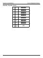
Symbology Additions
If scanner will not be used to read all symbologies (default setting), speed operation by using this menu to add only
the specific symbologies being used (add only the symbologies that are required).
ZZ
Start/End
Program
Menu
-[[-
B0
Disable all
-C1-
B2
Enable
Code 39
-C3-
B3
Enable
Codabar
-C!-
B4
Enable
IATA
-C5-
B5
Enable
Code 93
-C6-
B6
Enable
Code 128
-C7-
B7
Enable
MSI/Plessey
-C8-
B9
Enable
Telepen
-C:-
JZ
Enable
Trioptics
-K[-
R1
Enable
UPC
-S2-
R2
Enable
UPC+2
-S3-
R3
Enable
UPC+5
-S!-
CONTINUED ON NEXT PAGE...
Page 15
Manual No. 25-ULGPMU01-01
CCD Scanner
Series OPT Handheld
Symbology Additions (continued)
ZZ
Start/End
Program
Menu
-[[-
R4
Enable
EAN
-S5-
R5
Enable
EAN+2
-S6-
R6
Enable
EAN+5
-S7-
R7
Enable
Industrial
2of5
-S8-
R8
Enable
Interleaved
2of5
-S9-
Page 16
Manual No. 25-ULGPMU01-01
CCD Scanner
Series OPT Handheld
Setting the Number of
Characters to be Scanned
ZZ
Start/End
Program
Menu
-[[-
H0
Fixed length
OFF
all codes
H1
Fixed length
ON
all codes
-I1- Β
-I2-
HK
Fixed length
ON
selected codes
-IL-
HL
Min. length
selected codes
-IM-
HM
Max. length
selected codes
-IN-
Setting Code Specific Options - Options for specific codes may be configured affecting:
*
Enabling and disabling code variants and translations.
*
Data verification such as by mean of a check digit calculation. A check digit has a value that can be
calculated from the other data characters and is usually the last data character in a bar code.
*
Pre-editing of the data string such as removing the check digit and/or ST/SP characters.
The more common options are described here.
Check CD - Enables the check digit calculation. If the calculated check digit does not correspond to the check digit
in the bar code, then the bar code is ignored. The use of a check digit greatly improves the security of a bar code.
Do Not Check CD - Disables the check digit calculation. This option is required when the bar codes do not contain
a check digit or contain an invalid check digit.
Transmit CD - Enables the transmission of the check digit together with the data characters. If the check digit
calculation is disabled, the reader cannot differentiate anymore between a (valid) check digit and a data character. It
will therefore transmit all data characters of the label, including what could constitute a check digit.
Do Not Transmit CD - Disables the transmission of the check digit. If the check digit calculation is disabled, the
reader cannot differentiate between a (valid) check digit and a data character. It will therefore transmit all data
characters of the able, excluding the character that could constitute the check digit for the type of bar code.
Transmit ST/SP - Enables the transmission of the start and stop characters of a bar code.
Do Not Transmit ST/SP - Disables the transmission of the start and stop characters of a bar code.
Page 17
Manual No. 25-ULGPMU01-01
CCD Scanner
Series OPT Handheld
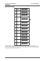
UPC Settings
Options for UPC-A and UPC-E bar codes.
NOTE: Abbreviations: Xmit = transmit; CD = Check digit; CC = Country code
ZZ
Start/End
Program
Menu
-[[-
E2
UPC-A
as EAN13
w/ CD
(13 digits)
-F3-
E3
UPC-A
w/ CD
(12 digits)
-F!- %
E4
UPC-A
w/ CD
(12 digits)
-F5-
E5
UPC-A
w/o CD
(11 digits)
-F6-
E6
UPC-E
w/ CC & CD
(8 digits)
-F7-
E7
UPC-E
w/o CC,
w/ CD
(7 digits)
-F8- %
E8
UPC-E
w/ CC,
w/o CD
(7 digits)
-F9-
E9
UPC-E
w/o CC & CD
(6 digits)
-F:-
6P
Xmit UPC-E
as UPC-A
w/ CD
(8 digits)
-7Q-
6Q
Do not
xmit UPC-E
as UPC-A
w/o CD
(7 digits)
-7R- %
Page 18
Manual No. 25-ULGPMU01-01
CCD Scanner
Series OPT Handheld
UPC Settings (continued)
Options for UPC-A - The UPC-A symbology is a fixed length symbology encoding 11 data digits, a check digit
and non printable start/stop characters. Supported characters are numeric digits 1 to 9.
An optional leading zero can be transmitted which, together with the data and the check digit, forms a 13 digit field
providing compatibility with the EAN-13 format.
String format:
Leading
data
check
0
digit
(11 digits)
UPC-A add-on 2/add-on 5 - The UPC-A symbology as described above can be succeeded by an additional 2 or 5
digit UPC-A code.
String format:
Leading
0
data
(11 digits)
check
digit
add-on
2 or 5
Options for UPC-A
*
Disable transmission of the leading zero
*
Disable transmission of the check digit
Options for UPC-E - The UPC-E symbology is a fixed length symbology encoding 6 data digits, a check digits and
non printable start/stop characters. Supported characters include numeric digits 0 to 9. An optional leading zero can
be transmitted which, together with the data and the check digit, forms an 8 digit field providing a compatibility with
the EAN-8 format.
String format:
Leading
data
check
0
digit
(6 digits)
UPC-E add-on 2/add-on 5 - The UPC-E symbology as described above can be succeeded by an additional 2 or 5
digit UPC-A code.
String format:
Leading
0
data
(6 digits)
check
digit
add-on
2 or 5
Options for UPC-E
*
Enable transmission of the leading zero
*
Disable transmission of the check digit
*
Transmit UPC-E as UPC-A
Page 19
Manual No. 25-ULGPMU01-01
CCD Scanner
Series OPT Handheld
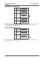
EAN-13 and EAN-8 Settings
ZZ
Start/End
Program
Menu
-[[-
6K
EAN-13
transmit CD
-7L- %
6J
EAN-13
do not
transmit CD
-7K-
6I
EAN-8
transmit CD
-7J- %
6H
EAN-8
do not
transmit CD
-7I-
IB
Disable
ISBN
translation
-JC- %
IA
Enable
ISBN
translation
-JB-
IK
Enable
ISBN if
possible
-JL-
HN
Disable
ISSN
translation
HO
Enable
ISSN
translation
4V
Enable
ISSN if
possible
-IO- Β
-IP-5W-
Page 20
Manual No. 25-ULGPMU01-01
CCD Scanner
Series OPT Handheld
EAN-13 and EAN-8 Settings
EAN-13 is a fixed length symbology encoding 12 data digits, a check digit and non printable start/stop characters.
Supported characters are numeric digits 0 to 9. The data may be translated into ISBN or ISSN format.
String format:
data
check
digit
(12 digits)
EAN-13 add-on 2/add-on 5 - The EAN-13 symbology as described above can be succeeded by an additional 2 or 5
digit UPC-A code.
String format:
data
check
add-on
digit
(12 digits)
2 or 5
EAN-8 is a fixed length symbology encoding 7 data digits, a check digit and non printable start/stop characters.
Supported characters are numeric digits 0 to 9.
String format:
data
check
digit
(7 digits)
EAN-8 add-on 2/add-on 5 - The EAN-8 symbology as described above can be succeeded by an additional 2 or 5
digit UPC-A code.
String format:
data
(7 digits)
check
digit
add-on
2 or 5
Options for EAN
*
Disable transmission of the check digit
*
Enable ISBN or ISSN translation
Enable ISBN or ISSN translation - If this option is enabled, an EAN-13 label is verified for the correct format and
transmitted as a 10 digit ISBN number or 8 digit ISSN number.
Page 21
Manual No. 25-ULGPMU01-01
CCD Scanner
Series OPT Handheld
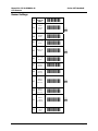
Code 39 Settings
ZZ
Start/End
Program
Menu
-[[-
C0
Check CD
-D1-
C1
Do not
check CD
-D2- %
D0
Xmit ST/SP
-E1-
D1
Do not
xmit ST/SP
-E2- %
D4
Full ASCII
-E%-
D5
Normal
Code 39
-E6- %
D8
Do not
xmit CD
-E9-
D9
Xmit CD
-E:- %
+K
Full ASCII
Code 39 if
possible
-,L-
+L
Enable
concat-enation
-,M-
+M
Disable
concat-enation
-,N- Β
Page 22
Manual No. 25-ULGPMU01-01
CCD Scanner
Series OPT Handheld
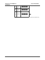
8D
Minimum
3 digits
-9E-
8E
Minimum
1 digit
-9F-
CONTINUED ON NEXT PAGE...
Page 23
Manual No. 25-ULGPMU01-01
CCD Scanner
Series OPT Handheld
Code 39 Settings (continued)
Code 39 is a variable length symbology with an optional check digit ("CD") and printable start/stop ("ST/SP")
characters. The following characters are supported:
•
Numeric characters 0 to 9
•
Alpha characters capital A to Z
•
Special characters - $ / + % and SPACE
•
Start/stop character is *
The checksum is calculated as the sum modulo 43 of the numerical value of the data characters.
In full ASCII mode, all 128 ASCII characters are supported. This is done by combining one of the characters +, %, $
or / with one of the alpha characters (A to Z).
String format:
start
char.
data (0 or
more characters)
check
digit
stop
char.
Options for Code 39:
*
Enable full ASCII conversion
*
Enable Italian Pharmaceutical conversion
*
Enable check digit
*
Disable transmission of the check digit
*
Enable transmission of start/stop
*
Enable leading A for Italian Pharmaceutical
*
Selection of the minimum number of data characters
Normal Code 39 - In this mode the decoded data characters are transmitted without further translation.
Full ASCII Code 39 - In this mode the decoded data characters are translated to full ASCII Code 39.
Full ASCII Code 39 if possible - In this mode the decoded data characters are translated to full ASCII code 39.
Invalid combinations are not translated and are transmitted as is.
Concatenation - If a Code 39 bar code contains a leading space, the data is stored into the reader's buffer without
the leading space. As soon as a Code 39 bar code is read without a leading space, the data is appended to the reader's
buffer and the entire buffer is transmitted and cleared for new data. In case a non Code 39 bar code bar is transmitted
and the buffer is cleared. The buffer size is reader dependant.
Page 24
Manual No. 25-ULGPMU01-01
CCD Scanner
Series OPT Handheld
Codabar Settings
ZZ
Start/End
Program
Menu
F0
Do not
transmit
start/stop
F1
Transmit
start/stop as
ABCD/TN*E
-G2-
F2
Transmit
start/stop as
abcd/tn*e
-G3-
F3
Transmit
start/stop as
ABCD/ABCD
-G!-
F4
Transmit
start/stop as
abcd/abcd
-G5-
H3
Enable
Codabar,
ABC and CX
-I!-
H4
Enable only
ABC code
-I5-
H5
Enable only
CX code
-I6-
H6
Check CD
-I7-
H7
Do not
check CD
-I8- %
H8
Transmit
CD
-I9- %
H9
Do not
transmit CD
-[[-G1- %
-I:/
Page 25
Manual No. 25-ULGPMU01-01
CCD Scanner
Series OPT Handheld
CONTINUED ON NEXT PAGE...
Page 26
Manual No. 25-ULGPMU01-01
CCD Scanner
Series OPT Handheld
Codabar Settings (continued)
ZZ
Start/End
Program
Menu
-[[-
HA
Enable
Codabar
normal mode
only
-IB- %
HB
Min. data
3 chars.
-IC-
HC
Min. data
1 char.
-ID-
HD
Enable space
insertion
-IE-
HE
Disable space
insertion
-IF- %
HF
Min. data
5 chars.
-IG- %
HH
Enable
interchar. gap
check
-II- %
HI
Disable
interchar. gap
check
-IJ-
Codabar Settings
Codabar (NW7) is a variable length symbology with an optional check digit and printable start/stop characters.
Supported characters include:
*
Numeric digits 0 to 9
*
special characters - $ : / , +
Page 27
Manual No. 25-ULGPMU01-01
CCD Scanner
*
Series OPT Handheld
start/stop characters are A, B, C or D
The checksum is calculated as the sum modulo 16 of the numerical values of all data characters.
String format:
start
char.
data (1 or
more chars.)
check
digit
stop
char.
CONTINUED ON NEXT PAGE...
Page 28
Manual No. 25-ULGPMU01-01
CCD Scanner
Codabar Settings (continued)
Series OPT Handheld
ABC-Code - The ABC code is an acronym for American Blood Commission. The code consists of two bar codes
which are decoded in one read cycle. the code is concatenated when the stop character of the first bar code and the
start character of the second bar code is a D. These two D's are not transmitted.
String format:
start data (1+ check data (1+ check stop
char.
chars.)
digit
chars.)
digit char.
CX-Code - The CX-Code consists of two are codes which are decoded in one read cycle. The code is concatenated
when the stop character of the first bar code is a C, and the start character of the second bar code is a B. The B and C
characters are not transmitted.
String format:
start
char.
data (1+
chars.)
check
digit
data (1+
chars.)
check stop
digit char.
Options for Codabar:
*
Enable ABC code concatenation.
*
Enable CD code concatenation.
*
Enable check digit check.
*
Disable transmission of the check digit.
*
Disable transmission of start/stop.
*
Selection of start/stop character translation.
*
Selection of minimum number of data characters.
*
Enable library space (CLSI) insertion.
*
Space insertion - This option inserts spaces in position 2, 7 and 13 of the data string for use in library systems.
ST/SP translation - This option enables the translation and transmission of the start and stop characters. Thus, if the
option ST/SP: abcd/tn*e is chosen, the start character is converted to lower case, e.g. from A, B, C or D to a, b, c or
d, respectively), and the stop character is converted from A, B, C or D to t, n, * or e, respectively.
Minimum data characters - Codabar labels are checked for a minimum of 1, 3 or 5 characters as set by the user. If
the number of characters in the label is shorter than the minimum selected, the label will be rejected. If the fixed
length option is used for Codabar type labels, then such labels will additionally be checked for fixed length. This
option will no longer be supported in future software releases.
Intercharacter gap check - This option enables the reading of Codabar labels with a large or irregular gap between
characters.
Page 29
Manual No. 25-ULGPMU01-01
CCD Scanner
Series OPT Handheld
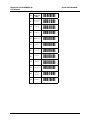
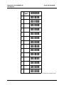
2of5 Settings
ZZ
Start/End
Program
Menu
E0
Transmit
CD
E1
Do not
transmit CD
G0
Do not
check CD
-H1- %
G1
Check CD
-H2-
GE
Min. data
1 char.
-HF-
GF
Min. data
3 chars.
-HG-
GI
Min. data
5 chars.
-GJ- %
GJ
Enable space
check for
Industrial 2of5
-GK- %
GK
Disable space
check for
Industrial 2of5
-HL-
-[[-F1- %
-F2-
CONTINUED ON NEXT PAGE...
Page 30
Manual No. 25-ULGPMU01-01
CCD Scanner
2of5 Settings (continued)
Series OPT Handheld
Code 2of5 is a variable length symbology with an optional check digit and non printable start and stop character.
Supported characters include numeric digits 0 to 9.
The checksum is calculated as the sum modulo 10 of the numerical values of all the data characters. The following
2of5 codes are supported.
Industrial 2of5 (D 2of5) - This symbology encodes a pair of digits in each symbol, the number of digits are
therefore always an even number. Information is carried in the bars and spaces. The start and stop pattern in not
unique inside the code. It is therefore essential to use the fixed length option to prevent partial reads.
Matrix 2of5 - This symbology encodes 1 digit in each character, the number of digits can therefore be an odd or an
even number. Information is carried in the bars and spaces.
String format - Industrial, Interleaved or Matrix 2of5:
leading
zero
data (1 or
more digits)
check
digit
Options for Code 2of5:
*
Disable transmission of the check digit
*
Enable check digit check
*
Selection of the minimum number of data characters
*
Disable space check for industrial 2of5
*
Transmit S Code as Interleaved 2of5
*
Minimum data characters - Code 2of5 are checked for a minimum of 1, 3 or 5 characters as set by the user. If the
number of characters in the label is less than the number set, the label will be rejected. If the fixed length option is
used for a Code 2of5 type label, then such label will also be checked for fixed length.
Intercharacter gap check - This option enables the reading of Industrial 2of5 labels with a large or irregular
spacing.
Page 31
Manual No. 25-ULGPMU01-01
CCD Scanner
Series OPT Handheld
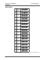
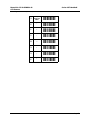
MSI/Plessey Settings
ZZ
Start/End
Program
Menu
-[[-
4A
Do not
check CD
-5B-
4B
Check 1 CD =
Mod 10
-5C- %
4C
Check 2 CD's
= Mod 10
/Mod 10
-%D-
4D
Check 2 CD's
= Mod 10
/Mod 11
-5E-
4E
Transmit CD1
-5F- %
4F
Transmit CD1
and CD2
-5G-
4G
Do not
transmit CD
-5H-
4R
Check 2 CD's
= Mod 11
/Mod 10
-5S-
MSI Plessey is a variable length symbology with one or two optional check digit calculations CD1 and CD2 and
non printable start/stop characters. Supported characters include numeric digits 0 through 9.
The checksum is calculated as the sum modulo 10 or 11 of the data characters. The checksum CD2 is calculated as
the sum modulo 10 or 11 of the data characters and CD1.
String format:
data (1 to
13 digits)
CD1
CD2
Options for MSI/Plessey:
*
Disable check digit check.
*
Selection of the check digit calculation.
*
Selection of the number of check digits to be transmitted.
Page 32
Manual No. 25-ULGPMU01-01
Series OPT Handheld
CCD Scanner
Check digit - If the check digit calculation is required, then the appropriate calculation method must be selected.
Do not transmit CD - The character positions CD1 and CD2 are not transmitted.
Transmit CD1 - The character position CD2 is not transmitted.
Transmit CD1 and CD2 - All characters in the label are transmitted.
Page 33
Manual No. 25-ULGPMU01-01
CCD Scanner
Series OPT Handheld
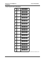
Code 128, EAN 128 Settings
ZZ
Start/End
Program
Menu
-[[-
JF
Enable
EAN 128
only
-KG-
MO
Enable FNC2
concat-enation
-NP-
MP
Disable FNC2
concat-enation
-NQ- %
OF
Disable
EAN 128
-PG- %
OG
Enable
EAN 128
if possible
-PH-
Code 128 is a variable length symbology with a mandatory check digit and non-printable start/stop characters.
Supported characters include:
*
All 128 ASCII characters;
*
4 non data function characters;
*
4 code set selection characters;
*
3 start characters; and
*
1 stop character.
The check is calculated as the sum modulo 103 of the start character and the weighted values of the data and special
characters.
data (1 or more characters)
String format:
EAN 128 - In this mode, the Code 128 data is translated to the EAN 128 format. EAN 128 data starts with the FNC1
character and separates 2 data fields with the FNC1 character. The first FNC1 character is translated to ]C1, and the
second FNC1 character is translated to ASCII GS (hex 1D) character.
String format:
data
data
<GS>
characters
characters
Enable EAN 128 only - In the mode, the decoded data characters are translated to the EAN 128 format. If the data
does not comply with the EAJ 128 format, then the label is rejected.
Enable EAN 128 if possible - In this mode, the decoded data characters are translated to the EAN 128 format. If the
data does not comply with the EAN 128 format, then the label is transmitted as Code 128.
]C1
Page 34
Manual No. 25-ULGPMU01-01
Series OPT Handheld
CCD Scanner
FNC2 Concatenation - If a Code 128 bar code contains a leading FNC2 character, the data is stored into the
reader's buffer. As soon as a Code 128 bar code is read without a leading FNC2 character, the data is appended to
the reader's buffer and the entire buffer is transmitted and cleared for new data. In case a non Code 128 bar code is
read, the data in the non-Code 128 bar code is transmitted and the buffer is cleared. The buffer size is reader
dependent.
Page 35
Manual No. 25-ULGPMU01-01
CCD Scanner
Series OPT Handheld
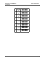
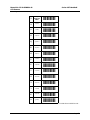
IATA Settings
ZZ
Start/End
Program
Menu
4H
Do not
check CD
4I
Check S/N
only
-5J-
4J
Check CPN,
S/N
-5K-
4K
Check CPN,
airline and
S/N
-5L-
4L
Transmit CD
-5M- %
4M
Do not
transmit CD
-5N-
-[[-!5I- %
IATA is a variable length symbology with an optional check digit and non printable start/stop characters. Supported
characters include numeric digits 0 through 9.
The checksum is calculated as the modulo seven of the data string. IATA is acronym for International Air Transport
Association.
String format - A possible format of IATA is as follows:
Code
Description
Digits
CPN
AC
FC
SN
CD
Coupon Airline Code Form Code Serial Number Check Digit
1
3
2
8
15
Options for IATA:
*
Enable check digit check.
*
Selection of the check digit calculation.
*
Disable transmission of the check digit.
Check digit - If the check digit calculation is required, then the appropriate calculation method must be selected.
Page 36
Manual No. 25-ULGPMU01-01
CCD Scanner
Series OPT Handheld
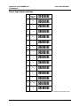
Telepen Settings
ZZ
Start/End
Program
Menu
D2
Numeric
mode
D3
ASCII mode
-[[-E3- %
-E!-
Telepen is a variable length symbology with a check digit and non printable start/stop characters. Supported
characters include numeric digits 00 through 99 in numeric mode, and all 128 ASCII characters in full ASCII mode.
The check digit calculation is derived from the sum of all data characters modulo 127. The check digit cannot be
transmitted.
String format:
Data
(1 to 32 characters)
Options for Telepen:
*
Selection of full ASCII mode.
Page 37
Manual No. 25-ULGPMU01-01
CCD Scanner
Series OPT Handheld
Case Conversion
ZZ
Start/End
Program
Menu
-[[-
YZ
No case
conversion
-Z[- %
YW
Convert to
upper case
-ZX-
YX
Convert to
lower case
-ZY-
YY
Exchange case
-ZZ-
String Options - This section describes the alterations which can be made to the format of the transmitted data string.
Options available are:
*
Case conversion
*
Transmission of a code identifier
*
Transmission of the code length
*
Transmission of a prefix
*
Transmission of a suffix
The prefix and/or suffix may include a code identifier and/or the code length.
String format:
prefix
bar code
data
suffix
Case conversion - The bar code may be converted to either lower of upper case or the case my be exchanged. These
options may be used if the user of a wedge has a preference to leave, for instance, the CAPSLOCK ON or if the host
required upper case characters only.
Page 38
Manual No. 25-ULGPMU01-01
CCD Scanner
Series OPT Handheld
Setting a Prefix or Suffix
A Prefix and Suffix consisting of a maximum 4 direct input entries each may be included in front and at the end of
the string, respectively.
The following steps are used to establish a Prefix or Suffix that will be transmitted with the bar code data.
1)
Scan Start/End Program Menu to enter programming mode.
2)
Scan the bar code representing the desired symbology you wish to add a Prefix or Suffix to.
3)
Scan the character(s) that comprise the Prefix or Suffix. Up to 4 numbers, letters or control characters may
be used.
4)
Scan Start/End Program Menu to exit programming mode.
Prefix Settings
ZZ
Start/End
Program
Menu
-[[-
GL
Matrix 2of5
-HM-
I8
IATA
-J9-
L8
Telepen
-M9-
M0
UPC-A
+ add-on
/N1-
M1
UPC-E
+ add-on
-N2-
M2
EAN-13
+ add-on
-N!-
M3
EAN-8
+ add-on
-N!-
M4
Code 39
-N5-
M5
Codabar
-N6-
M6
Industrial 2of5
-N7-
CONTINUED ON NEXT PAGE...
Page 39
Manual No. 25-ULGPMU01-01
CCD Scanner
Prefix Settings (continued)
Series OPT Handheld
ZZ
Start/End
Program
Menu
-[[-
M7
Interleaved
2of5
-N8-
M8
Code 93
-N9-
M9
Code 128
-N:-
N0
MSI/Plessey
-O1-
N1
UPC-A
-O2-
N2
UPC-E
-O3-
N3
EAN-13
-O!-
N4
EAN-8
-O5-
RY
All codes
-SZ-
MG
Clear all
prefixes
-NH-
MZ
Preamble
-N[-
Page 40
Manual No. 25-ULGPMU01-01
CCD Scanner
Series OPT Handheld
Suffix Settings
ZZ
Start/End
Program
Menu
-[[-
GM
Matrix 2of5
-HN-
I9
IATA
-J:-
L9
Telepen
-M:-
N5
MSI/Plessey
-O6-
N6
UPC-A
-O7-
N7
UPC-E
-O8-
N8
EAN-13
-O9-
N9
EAN-8
-O:-
O0
UPC-A
+ add-on
-P1-
O1
UPC-E
+ add-on
-P2-
O2
EAN-13
+ add-on
-P3-
O3
EAN-8
+ add-on
-P!-
O4
Code 39
-P5-
O5
Codabar
-P6-
CONTINUED ON NEXT PAGE...
Page 41
Manual No. 25-ULGPMU01-01
CCD Scanner
Suffix Settings (continued)
Series OPT Handheld
ZZ
Start/End
Program
Menu
-[[-
O6
Industrial
2of5
-P7-
O7
Interleaved
2of5
-P8-
O8
Code 93
-P9-
O9
Code 128
-P:-
PR
Clear all
suffixes
-QS-
PS
Postamble
-QT-
RZ
All Codes
-S[-
Page 42
Manual No. 25-ULGPMU01-01
CCD Scanner
Series OPT Handheld
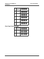
Direct Input Keyboard Keys
ZZ
Start/End
Program
Menu
-[[-
8J
F1
-9K-
8K
F2
-9L-
8L
F3
-9M-
8M
F4
-9N-
8N
F5
-9O-
8O
F6
-9P-
8P
F7
-9Q-
8Q
F8
-9R-
8R
F9
-9S-
8S
F10
-9T-
8T
F11
-9U-
8U
F12
-9V-
9X
Backspace
-:Y-
7H
TAB
-8I-
CONTINUED ON NEXT PAGE...
Page 43
Manual No. 25-ULGPMU01-01
CCD Scanner
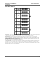
Direct Input Keyboard Keys (continued)
Series OPT Handheld
ZZ
Start/End
Program
Menu
7I
Carriage
return
7Q
Enter
(numeric pad)
-8R-
7R
Enter make
(alpha pad)
-8S-
7S
Enter make
and break
(alpha pad)
-8E-
7J
ESC
-8K-
7K
Arrow down
-8L-
7L
Arrow up
-8M-
7M
Arrow right
-8N-
7N
Arrow left
-8O-
7T
<DEL>
-8U-
VQ
<INSERT>
-WR-
VR
<HOME>
-WS-
VS
<END>
-WT-
7O
Page up
-8P-
-[[-8J- %
CONTINUED ON NEXT PAGE...
Page 44
Manual No. 25-ULGPMU01-01
CCD Scanner
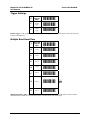
Direct Input Keyboard Keys (continued)
Series OPT Handheld
ZZ
Start/End
Program
Menu
-[[-
7P
Page down
-8Q-
7U
Left
<Shift>
-8V-
7W
Left
<Ctrl>
-8X-
7Y
Left
<Alt>
-8Z-
7V
Right
<Shift>
-8W-
7X
Right
<Ctrl>
-8Y-
7Z
Right
<Alt>
-8[-
9S
CAPSLOCK
-:T-
Page 45
Manual No. 25-ULGPMU01-01
CCD Scanner
Series OPT Handheld
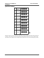
Direct Input Characters
ZZ
Start/End
Program
Menu
-[[-
5A
<SPACE>
-6B-
5B
!
-6C-
5C
"
-6D-
5D
#
-6E-
5E
$
-6F-
5F
%
-6G-
5G
&
-6H-
5H
'
-6I-
5I
(
-6J-
5J
)
-6K-
5K
*
-6L-
5L
+
-6M-
5M
,
-6N-
5N
-
-6O-
CONTINUED ON NEXT PAGE...
Page 46
Manual No. 25-ULGPMU01-01
CCD Scanner
Direct Input Characters (continued)
Series OPT Handheld
ZZ
Start/End
Program
Menu
-[[-
5O
.
-6P-
5P
/
-6Q-
6A
:
-7B-
6B
;
-7C-
6C
<
-7D-
6D
=
-7E-
6E
>
-7F-
6F
?
-7G-
6G
@
-7H-
7A
[
-8B-
7B
\
-8C-
7C
]
-8D-
7D
^
-8E-
7E
_
-8F-
CONTINUED ON NEXT PAGE...
Page 47
Manual No. 25-ULGPMU01-01
CCD Scanner
Direct Input Characters (continued)
Series OPT Handheld
ZZ
Start/End
Program
Menu
-[[-
7F
`
-8G-
9T
{
-:U-
9U
|
-:V-
9V
}
-:W-
9W
~
-:X-
CONTINUED ON NEXT PAGE...
Page 48
Manual No. 25-ULGPMU01-01
CCD Scanner
Direct Input Characters (continued)
Series OPT Handheld
ZZ
Start/End
Program
Menu
-[[-
Q0
0
-R1-
Q1
1
-R2-
Q2
2
-R3-
Q3
3
-R!-
Q4
4
-R5-
Q5
5
-R6-
Q6
6
-R7-
Q7
7
-R8-
Q8
8
-R9-
Q9
9
-R:-
0A
A
-1B-
0B
B
-1C-
0C
C
-1D-
CONTINUED ON NEXT PAGE...
Page 49
Manual No. 25-ULGPMU01-01
CCD Scanner
Direct Input Characters (continued)
Series OPT Handheld
ZZ
Start/End
Program
Menu
-[[-
0D
D
-1E-
0E
E
-1F-
0F
F
-1G-
0G
G
-1H-
0H
H
-1I-
0I
I
-1J-
0J
J
-1K-
0K
K
-1L-
0L
L
-1M-
0M
M
-1N-
0N
N
-1O-
0O
O
-1P-
0P
P
-1Q-
0Q
Q
-1R-
CONTINUED ON NEXT PAGE...
Page 50
Manual No. 25-ULGPMU01-01
CCD Scanner
Direct Input Characters (continued)
Series OPT Handheld
ZZ
Start/End
Program
Menu
-[[-
0R
R
-1S-
0S
S
-1T-
0T
T
-1U-
0U
U
-1V-
0V
V
-1W-
0W
W
-1X-
0X
X
-1Y-
0Y
Y
-1Z-
0Z
Z
-1[-
$A
a
-%B-
$B
b
-%C-
$C
c
-%D-
$D
d
-%E-
$E
e
-%F-
CONTINUED ON NEXT PAGE...
Page 51
Manual No. 25-ULGPMU01-01
CCD Scanner
Direct Input Characters (continued)
Series OPT Handheld
ZZ
Start/End
Program
Menu
-[[-
$F
f
-%G-
$G
g
-%H-
$H
h
-%I-
$I
i
-%J-
$J
j
-%K-
$K
k
-%L-
$L
l
-%M-
$M
m
-%N-
$N
n
-%O-
$O
o
-%P-
$P
p
-%Q/
$Q
q
-%R-
$R
r
-%S-
$S
s
-%T-
CONTINUED ON NEXT PAGE...
Page 52
Manual No. 25-ULGPMU01-01
CCD Scanner
Direct Input Characters (continued)
Series OPT Handheld
ZZ
Start/End
Program
Menu
-[[-
$T
t
-%U-
$U
u
-%V-
$V
v
-%W-
$W
w
-%X-
$X
x
-%Y-
$Y
y
-%Z-
$Z
z
-%[-
Page 53
Manual No. 25-ULGPMU01-01
CCD Scanner
Series OPT Handheld
Direct Input Control Characters
ZZ
Start/End
Program
Menu
-[[-
9G
^@(NULL)
-:H-
1A
^A(SOH)
-2B-
1B
^B(STX)
-2C-
1C
^C(ETX)
-2D-
1D
^D(EOT)
-2E-
1E
^E(ENQ)
-2F-
1F
^F(ACK)
-2G-
1G
^G(BEL)
-2H-
1H
^H(BS)
-2I-
1I
^I(HT)
-2J-
1J
^J(LF)
-2K-
1K
^K(VT)
-2L-
1L
^L(FF)
-2M-
1M
^M(CR)
-2N-
CONTINUED ON NEXT PAGE...
Page 54
Manual No. 25-ULGPMU01-01
CCD Scanner
Direct Input Control Characters (continued)
Series OPT Handheld
ZZ
Start/End
Program
Menu
-[[-
1N
^N(SO)
-2O-
1O
^O(SI)
-2P-
1P
^P(DLE)
-2Q-
1Q
^Q(DC1)
-2R-
1R
^R(DC2)
-2S-
1S
^S(DC3)
-2T-
1T
^T(DC4)
-2U-
1U
^U(NAK)
-2V-
1V
^V(SYN)
-2W-
1W
^W(ETB)
-2X-
1X
^X(CAN)
-2Y-
1Y
^Y(EM)
-2Z-
1Z
^Z(SUB)
-2[-
9A
^[(ESC)
-:B-
CONTINUED ON NEXT PAGE...
Page 55
Manual No. 25-ULGPMU01-01
CCD Scanner
Direct Input Control Characters (continued)
Series OPT Handheld
ZZ
Start/End
Program
Menu
-[[-
9B
^\(FS)
-:C-
9C
^](GS)
-:D-
9D
^^(RS)
-:E-
9E
^_(US)
-:F-
9F
DEL
(ASCII 127)
-:G-
Direct Input Code ID/Length
ZZ
Start/End
Program
Menu
-[[-
$2
Code
identification
-%3-
$3
Code length
-%!-
Page 56
Manual No. 25-ULGPMU01-01
CCD Scanner
Series OPT Handheld
Read Mode Settings
ZZ
Start/End
Program
Menu
-[[-
S0
Single
read
-T1-
S1
Multiple
read
S2
Continuous
read
-T3-
XA
Add-on
wait mode
disabled
-YB-
XB
Add-on
wait mode
0.25 sec.
-TC-
XC
Add-on
wait mode
0.50 sec.
-YD- %
XD
Add-on
wait mode
0.70 sec.
-YE-
-T2- %
Single Read - When a bar code has been decoded, the reader will be turned OFF. The reader must be triggered again
to read another label. This option and "Disable trigger" cannot be programmed at the same time.
Multiple Read - When a bar code has been decoded, the reader will stay ON for a time as set by "read time
settings" or indefinitely if the trigger switch has been disabled. The same label can only be decoded again after the
label has not been detected for a number of scans.
Continuous Read - The reader will produce as much data as it can decode regardless whether it is the same or not.
This mode is mainly used for demonstration and diagnosis.
Add-on Wait Mode - Used if UPC/EAN with add-on is enabled. The reader searches within the selected time for a
valid add-on code. If a valid add-on code is found, the reader transmits the data immediately. If nothing is found
behind the code, the scanner will transmit the data without add-on. If something is found behind the code, the reader
ignored the code in case it is not a valid add-on.
Page 57
Manual No. 25-ULGPMU01-01
CCD Scanner
Series OPT Handheld
Trigger Settings
ZZ
Start/End
Program
Menu
-[[-
S7
Disable
trigger
-T8-
S8
Enable
trigger
-T9-
Disable Trigger - This is applicable to readers which have a trigger switch. When this option is selected, the reader
will stay ON all the time.
Multiple Read Reset Time
ZZ
Start/End
Program
Menu
-[[-
AH
50 ms
-BI-
AI
100 ms
-BJ-
AJ
200 ms
-BK-
AK
300 ms
-BL-
AL
400 ms
-BM-
AM
500 ms
-BN- %
AN
600 ms
-BO-
Multiple Read Reset Time - This option can be used in conjunction with multiple read mode. It sets the time the
reader should be pointed away from the label before it can decode the same label again.
Page 58
Manual No. 25-ULGPMU01-01
CCD Scanner
Series OPT Handheld
Quiet Zone Settings
ZZ
Start/End
Program
Menu
-[[-
YN
No margin
check
-ZO-
YO
Margin
check 1/7
normal
-ZP-
YP
Margin
check 2/7
normal
-ZQ-
YQ
Margin
check 3/7
normal
-ZR-
YR
Margin
check 4/7
normal
-ZS-
YS
Margin
check 5/7
normal
-ZE-
YT
Margin
check 6/7
normal
-ZU-
YU
Margin
check
normal
-ZV- %
With these settings, the reader can decode bar codes that have smaller start and/or end margins than specified for the
symbology. These settings may increase the possibility of partial and ghost reads, hence do not use smaller margin
checks than necessary. Replace any bar code labels with ones that have the correct start and end margins if possible.
Page 59
Manual No. 25-ULGPMU01-01
CCD Scanner
Series OPT Handheld
Read Time Settings
ZZ
Start/End
Program
Menu
-[[-
Y0
0 seconds
-Z1-
Y1
1 second
-Z2-
Y2
2 seconds
-Z3- %
Y3
3 seconds
-Z!-
Y4
4 seconds
-Z5-
Y5
5 seconds
-Z6-
Y6
6 seconds
-Z7-
Y7
7 seconds
-Z8-
Y8
8 seconds
-Z9-
YL
Read time
x 10
-ZM-
YM
Indefinitely
-ZN-
Read Time Settings - the length of the period that the reader is ON after the trigger switch is pressed, or (in
multiple or continuous read mode) after a label has been read. Selecting a read time of 0 means that the reader will
stay ON as long as the trigger switch is being pressed. Selecting a read time for readers without a trigger switch, or
when the trigger switch is disabled, has no effect.
Page 60
Manual No. 25-ULGPMU01-01
CCD Scanner
Series OPT Handheld
Redundant Decoding Settings
ZZ
Start/End
Program
Menu
-[[-
X0
No
redundancy
-Y1-
X1
Two times
redundant
-Y2- %
X2
Three times
redundant
-Y3-
X3
Four times
redundant
-Y!-
Redundancy Settings - This is the number of times that a label must be correctly decoded before it is transmitted.
Selecting a higher redundancy count makes reading slower, but it reduces the probability of reading errors,
especially when labels of poor definition are used.
Positive and Negative Bar Codes
ZZ
Start/End
Program
Menu
-[[-
V2
Positive
bar codes
-W3-
V4
Both positive
and negative
bar codes
-W5- %
Positive and Negative Bar Codes - Usually bar codes are printed black on white, but sometime white on black.
These labels are called positive and negative, respectively.
Page 61
Manual No. 25-ULGPMU01-01
CCD Scanner
Series OPT Handheld
Buzzer Settings
ZZ
Start/End
Program
Menu
W8
Enable
software
buzzer
-X9- %
W0
Disable
buzzer
-X1-
W1
Single tone
buzzer
-X2-
W2
High - low
buzzer
-X3- %
W3
Low - high
buzzer
-X!-
W7
Buzzer
duration
50 msec.
-X8-
W4
Buzzer
duration
100 msec.
-X5-
W5
Buzzer
duration
200 msec.
-X6- %
W6
Buzzer
duration
400 msec.
-X7-
T0
Buzzer
volume
maximum
-U1- %
T1
Buzzer
volume
loud
-[[-
-U2-
Page 62
Manual No. 25-ULGPMU01-01
CCD Scanner
Series OPT Handheld
T2
Buzzer
volume
normal
-U3-
T3
Buzzer
volume
minimum
-U!-
VY
Buzzer before
transmission
-WZ- %
CONTINUED ON NEXT PAGE...
Page 63
Manual No. 25-ULGPMU01-01
CCD Scanner
Buzzer Settings
Series OPT Handheld
ZZ
Start/End
Program
Menu
-[[-
VZ
Buzzer
after
transmission
-W[-
GD
Disable
startup buzzer
-HE-
GC
Enable startup
buzzer
-HD-
Buzzer Settings - These options determine the buzzer type, tone, duration and loudness. By default, the buzzer is
disabled for Linker type readers.
Buzzer Type - The buzzer may be disabled or enabled as either a hardware of software buzzer. Not all readers
support both a hardware and software buzzer.
Buzzer Tone - If a software buzzer is used, the buzzer tone may be selected.
Buzzer Duration and Volume - If a software buzzer is used, a buzzer duration of 50, 100, 200 or 400 msec. may be
selected. Volume may also be adjusted.
Buzzer Before Transmission - The good read buzzer will be activated after decoding the bar code, but before
transmission. During transmission, the buzzer sequence will be completed.
Buzzer After Transmission - The good read buzzer will be activated after transmission.
Enable Startup Buzzer - When this option is selected, the reader will generate a single good read buzzer to
indicate the reader is ready after the reader is supplied with power.
Disable Startup Buzzer - When this option is selected, the reader will not sound the buzzer after the reader is
supplied with power.
Page 64
Manual No. 25-ULGPMU01-01
CCD Scanner
Series OPT Handheld
Good Read LED
ZZ
Start/End
Program
Menu
-[[-
T4
Disable
indicator
-U5-
T5
Indicator
duration
0.2 sec.
-U6- %
T6
Indicator
duration
0.4 sec.
-U7-
T7
Indicator
duration
0.8 sec.
-U8-
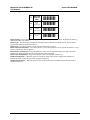
ZZ
Start/End
Program
Menu
-[[-
Z1
Transmit
software
version
-[2-
Z3
Transmit
settings
-[!-
ZA
Transmit
ASCII
printable
string
YV
Transmit
ASCII control
string
-ZW-
TH
Error msg.
label
-UI-
TI
Error msg. no
decode
-UJ-
Diagnostics
-[B-
Page 65