1
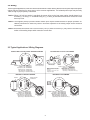
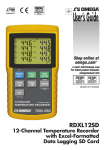
User’s Guide
Shop online at
omega.com
e-mail: [email protected]
For latest product manuals:
omegamanual.info
DPF500 Series
Ratemeter/Totalizer
OMEGAnet ® Online Service
omega.com
Internet e-mail
[email protected]
Servicing North America:
U.S.A.:
ISO 9001 Certified
Canada:
One Omega Drive, P.O. Box 4047
Stamford, CT 06907-0047
TEL: (203) 359-1660
e-mail: [email protected]
976 Bergar
Laval (Quebec) H7L 5A1, Canada
TEL: (514) 856-6928
e-mail: [email protected]
FAX: (203) 359-7700
FAX: (514) 856-6886
For immediate technical or application assistance:
U.S.A. and Canada: Sales Service: 1-800-826-6342 / 1-800-TC-OMEGA®
Customer Service: 1-800-622-2378 / 1-800-622-BEST®
Engineering Service: 1-800-872-9436 / 1-800-USA-WHEN®
TELEX: 996404 EASYLINK: 62968934 CABLE: OMEGA
Mexico:
En Espan˜ol: (001) 203-359-7803
FAX: (001) 203-359-7807
e-mail: [email protected]
[email protected]
Servicing Europe:
Benelux:
Postbus 8034, 1180 LA Amstelveen, The Netherlands
TEL: +31 (0)20 3472121
FAX: +31 (0)20 6434643
Toll Free in Benelux: 0800 0993344
e-mail: [email protected]
Czech Republic:
Frystatska 184, 733 01 Karviná, Czech Republic
TEL: +420 (0)59 6311899
FAX: +420 (0)59 6311114
Toll Free: 0800-1-66342
e-mail: [email protected]
France:
11, rue Jacques Cartier, 78280 Guyancourt, France
TEL: +33 (0)1 61 37 2900
FAX: +33 (0)1 30 57 5427
Toll Free in France: 0800 466 342
e-mail: [email protected]
Germany/Austria: Daimlerstrasse 26, D-75392 Deckenpfronn, Germany
TEL: +49 (0)7056 9398-0
Toll Free in Germany: 0800 639 7678
e-mail: [email protected]
United Kingdom:
ISO 9002 Certified
FAX: +49 (0)7056 9398-29
One Omega Drive, River Bend Technology Centre
Northbank, Irlam, Manchester
M44 5BD United Kingdom
TEL: +44 (0)161 777 6611
FAX: +44 (0)161 777 6622
Toll Free in United Kingdom: 0800-488-488
e-mail: [email protected]
It is the policy of OMEGA Engineering, Inc. to comply with all worldwide safety and EMC/EMI
regulations that apply. OMEGA is constantly pursuing certification of its products to the European New
Approach Directives. OMEGA will add the CE mark to every appropriate device upon certification.
The information contained in this document is believed to be correct, but OMEGA accepts no liability for any
errors it contains, and reserves the right to alter specifications without notice.
WARNING: These products are not designed for use in, and should not be used for, human applications.
Table of Contents
Page
Chapter 1
Introduction
1.1 Unpacking...................................................................................................................... 1
1.2 Description..................................................................................................................... 1
1.3 Features ........................................................................................................................ 1
1.4 Available Models ............................................................................................................ 1
1.5 Available Options/Accessories ...................................................................................... 1
Chapter 2
Installation
2.1 Battery Installation ......................................................................................................... 2
2.2 Battery Replacement ..................................................................................................... 2
2.3 Dimensions .................................................................................................................... 3
2.4 Wiring ............................................................................................................................ 4
2.5 Typical Applications/Wiring Diagrams ............................................................................ 4
Chapter 3
20 Point Linearization Operation
3.1 20 Point Linearization (-LIN option) ............................................................................... 5
Chapter 4
Programming
4.1 Explanation of Display Prompts..................................................................................... 5
4.2 Programming Flowchart ................................................................................................ 8
Chapter 5
Operation
5.1 General ......................................................................................................................... 10
5.2 Maintenance ................................................................................................................. 10
Chapter 6
Error Messages/Analog Output Calibration
6.1 Error Messages ............................................................................................................ 11
6.2 Analog Output Calibration............................................................................................. 11
Chapter 7
Specifications
7.1 Specifications ............................................................................................................... 12
i
THIS PAGE INTENTIONALLY BLANK
ii
Chapter 1 Introduction
1.1 Unpacking
Remove the Packing List and verify that you have received all equipment. If you have any questions about the
shipment, please call OMEGA Customer Service Department.
When you receive the shipment, inspect the container and equipment for any signs of damage. Note any evidence
of rough handling in transit. Immediately report any damage to the shipping agent.
NOTE: The carrier will not honor any damage claims unless all shipping material is saved for their examination.
After examining and removing contents, save packaging material and carton in the event reshipment is
necessary.
1.2 Description
Featuring 5 digits of rate and 8 digits of total, the DPF500 meter is a battery powered indicator capable of accepting
magnetic pickup, DC pulse and switch closure inputs. The unit can be ordered with an optional 4-20mA output. The
DPF500-MA uses the 4-20mA loop to provide power when this output is used.
1.3 Features
• Magnetic Pickup Input, Contact Closure Input, DC Pulse Input (Optically Isolated)
• Displays Rate & Total Simultaneously
• 5 Digit Rate Display
• 8 Digit Totalizer Display
• 4-20mA Analog Output (-MA option)
• Powered From Internal Battery, or 4-20 mA Output Loop (-MA option)
• 20 Pt. Linearization (-LIN option)
• Isolated Scaled Pulse Output
1.4 Available Models
The following models are available from OMEGA Engineering, Inc.
PART NUMBER
DPF501
DPF502
DPF503
DESCRIPTION
Panel Mount, Battery Powered* Ratemeter and Totalizer (NEMA-4 Front)
Wall Mount, Battery Powered* Ratemeter and Totalizer (NEMA-4 Enclosure)
Explosion Proof, Battery Powered* Ratemeter and Totalizer
Class I, Division I, Groups B, C & D
Class II, Division I, Groups E, F & G
* All units may be powered from an external 8.5 -30 VDC to prolong internal battery life.
1.5 Available Options/Accessories
The following options (available at the time of ordering) are available from OMEGA Engineering, Inc.
PART NUMBER
-MA
-LIN
-BAT
-ET
DESCRIPTION
Loop Powered with 4-20 mA output
20-point linearization
Battery Pack
Extended Temperature Range
The following accessories are available from OMEGA Engineering, Inc.
PART NUMBER
DPF5-BP
DPF501-BAT
FPW-15
DESCRIPTION
External battery pack with 2 "C" size batteries and 12" leads
Spare battery
15 VDC power supply
1
Chapter 2 Installation
2.1 Battery Installation:
All DPF500 models are shipped without the battery(ies) installed. This preserves battery life when the unit is not in
service. When using external DPF5-BP, mount within 12" and plug connector into 3 position square posts (see Fig
1). Polarity is not a concern because center is common.
To install the battery, begin by locating the battery holder. The DPF502 and DPF503 require opening the enclosure
cover and removing the DPF500 to expose the battery holder.
The plus terminal of the battery is marked with a (+) symbol stamped into the battery holder. Be sure to install the
battery(ies) correctly.
Install battery(ies) to begin setup procedure. See Programming Flowchart to setup desired operating parameters.
2.2 Battery Replacement:
The DPF500 has a battery monitor feature which illuminates when the lithium battery voltage approaches its end
of life. A descriptor, “BAT”, illuminates when the battery voltage falls below this predetermined value. The low battery detector operates correctly with all power options.
The battery, or batteries, should be replaced within several weeks of the first occurrence of low battery warning,
“BAT”. Left unattended, the unit may become inaccurate, cease to operate or malfunction.
Before replacing the battery(ies), Press the ← (left arrow) key to save the totalizer. The display will show "SAVE
TOTAL". This will save the current total value and the total will resume from this value when the new battery(ies)
is(are) installed. NOTE: If the display starts to flash after the "SAvE totAL" message times out, press the "E" (enter)
key. If the message "E FLASH" is displayed, then there was not enough power left to save the setup and totalizer
to flash memory. At this point you must record the totalizer and setup information and re-enter the setup data after
the new battery(ies) is(are) installed.
Install new battery(ies) as described above.
Fig 1
Battery
12 1110 9 8 7
6 5 4 3 21
Rear View
2
DPF5-BP
Connector
2.3 Dimensions
DPF501
DPF5-BP Accessory
Outside Dotted Line Shows
Outside Panel Dimension
(4.00" Diameter)
3.582" Dia. Bolt Circle
.125" Holes to be 120° Apart
3.062" (77.77)
Dia. Cutout
Panel
Cutout
.10
(2.54)
1.7
(43)
2.875
(73)
4.00
(101.6)
Dimensions are in inches (mm)
120°
Dimensions are in inches (mm)
Dimensions are in inches (mm)
DPF502
DPF503
To access terminals, unscrew cover and loosen 2 panel screws.
(If screws are removed, spacers may drop out.) Terminals are on
bottom side of PC board.
#8 Screw Mounting holes molded directly under cover
screws. Max. screw head .29" (Typ. 4 places)
4.92(125)
4.33 (110)
5.00
(127)
4.63
(117)
To access terminals, remove cover
and 4 panel screws.Terminals are
on bottom side of PC board.
3/4 NPT
(2) HLS
Panel Screws
4.33
(110)
E
M
1.97
(50)
.43
(11)
TOP VIEW (PANEL INSTALLED)
5.00
(127)
.98
(25)
4.92
(125)
E
.18 (5)
M
5/16
4.25
(108)
BOTTOM VIEW
5.25
(133)
Dimensions are in inches (mm)
Dimensions are in inches (mm)
3
2.4 Wiring
Several typical applications of the DPF500 are shown below. Please observe that the various pulse inputs and power
options may be intermixed in many ways to solve common applications. The isolated pulse output may be freely
used so long as proper polarity is observed.
Caution: When 4-20 mA loop option is provided, the power wiring to the loop power option should always be to
terminals (+) 12 and (-) 11. Accidental wiring to (+) 12 and (-)6 should be avoided since excessive current
flow may result.
Caution: The magnetic pickup input and contact closure input require isolated sensors for proper operation. Accidental connections to earth may result in erroneous operation of the analog output and/or excessive
current flow.
Caution: Accidental connections from circuit common (3 or 6) to earth or terminal (11) may result in erroneous operation of the analog output and/or excessive current flow.
2.5 Typical Applications / Wiring Diagrams
CONTACT INPUT / PULSE OUTPUT / BATTERY POWERED
ISOLATED INPUT / 4-20mA LOOP POWERED
4-20mA (+)/DC In (+) 12
4-20mA (-) 11
Opto Input (+) 10
NOTE: Separate power supplies
Opto Input (-) 9
are recommended to isolate output
from input.
Opto Out (+) 8
If isolation is not a concern, use a
Opto Out (-) 7
single power supply
654321
654321
Flowmeter
with DC Pulse Output
Flowmeter with
Switch Closure Output
1 Mag Input1
2 Mag Input 2
3 Shield/GND
4 Reset Input
5 Contact Input
6 Common/ DC In (-)
+
-
24 VDC
Power
Supply
PSU-24B
123456
4-20mA (+)/DC In (+) 12
4-20mA (-) 11
Opto Input (+) 10
Opto Input (-) 9
Opto Out (+) 8
Opto Out (-) 7
+
12 1110 9 8 7
12 1110 9 8 7
-
4 1
DPF76 Totalizer
+
To Shield
Pin 3
-
Strip Chart
Recorder
+
24 VDC
Power Supply
PSU-24B
1 Mag Input1
2 Mag Input 2
3 Shield/GND
4 Reset Input
5 Contact Input
6 Common/ DC In (-)
MAG INPUT / DC POWERED
MAG INPUT / DPF5-BP POWERED
654321
+
-
12 1110 9 8 7
12 1110 9 8 7
4-20mA (+)/DC In (+) 12
4-20mA (-) 11
Opto Input (+) 10
Opto Input (-) 9
Opto Out (+) 8
Opto Out (-) 7
15 VDC
Power
Supply
FPW-15
Remote
Reset Switch
1 Mag Input1
2 Mag Input 2
3 Shield/GND
4 Reset Input
5 Contact Input
6 Common/ DC In (-)
4-20mA (+)/DC In (+) 12
4-20mA (-) 11
Opto Input (+) 10
Opto Input (-) 9
Opto Out (+) 8
Opto Out (-) 7
Turbine Meter with
Mag Pickup
4
654321
DPF5-BP PLUG-IN
CONNECTOR
DPF5-BP
Remote
Reset Switch
1 Mag Input1
2 Mag Input 2
3 Shield/GND
4 Reset Input
5 Contact Input
6 Common/ DC In (-)
Turbine Meter with
Mag Pickup
Chapter 3 20 Point Linearization (-LIN option)
3.1 20 Point Linearization Operation (-LIN option)
A 20 point linearization table is used to construct a curve describing the relationship of K-Factor and input
frequency. The measured input frequency is used to access the table. A linear interpolation of adjacent
point pairs is used to arrive at the K-Factor at that input frequency. The flow rate and total are then computed based upon the K-Factor for that measurement sample.
NOTE: For best performance and resolution choose as many decimal places as possible in the KFactor.
Example: Enter a K-Factor of 1 as 1.000.
Chapter 4 Programming
4.1 Explanation of Display Prompts
Save Total: (Save Total) Press the E key while the unit is running to save the total value. The display will show
"save total" for a few seconds. This is a very useful "scratch pad" to save and restore total when replacing
the battery(ies)
ent Code: (enter code) This prompt will only appear if the panel lock is ON. Press the ↑ key to increment each digit.
Press the ← key to step to the next digit to the left. Press the E key to enter the 5 digit code. If the entered
code is correct, the display will advance to the next menu prompt (CLr tot). If incorrect, the display will return
to the run mode.
Clr tot: (clear total) Clears (resets) the totalizer. Press the E key to clear the total and return to the run mode. Press
the M key to skip and advance to the next menu selection.
fdeC: (factor decimal) Sets the decimal location for the factor. This location is restricted to 3 places (99.999). The use
of this decimal automatically limits the number of decimal locations allowable in the rate and total to acceptable
ranges. Press the ← key to move the decimal. Press the E key to select the displayed decimal location.
NOTE:
For best performance and resolution choose as many decimal places as possible in the K-Factor.
Example: Enter a K-Factor of 1 as 1.000.
faC lInear/20poInt: (factor type) This prompt will only appear if the unit is ordered with the 20 point linearization option. The 20 poInt linearization selection is recommended for flow meters whose K-factors change with different
flow rates. This selection allows users to enter up to 20 different frequencies with 20 corresponding K-factors for
different flow rates. The lInear setting is used for flow meters whose output is linear over its' entire operating
flow range. Press the ↑ key to step to the desired choice. Press the E key to enter the displayed factor type.
No / yes set Pnts: (set 20 point?) This prompt allows the user to skip the 20 point setup routine. Select yes for
initial setup or to change the present 20 point values. Select No to skip and keep the existing values.
faC : (factor) This prompt appears on all units with linear inputs. The Factor is the number of pulses per unit volume
for the flow sensor. The pulses/unit volume is implied by the totalizer descriptor when a descriptor is used. The
implied units for the Factor are then as follows:
GAL
pulses/gallon
LIT
pulses/liter
FT3
pulses/ft3
M3
pulses/M3
Factors from 0.0001 to 99999999 may be used. A "0" value for the factor is not allowed and the unit will default
to "1" in LSD if a "0" entry is attempted . The factor is displayed on the subsidiary (lower) display. Press the ↑
key to increment each digit. Press the ← key to step to the next digit to the left. Press the E key to enter the
displayed factor.
5
4.1 Explanation of Display Prompts (continued)
fr# : (frequency for point #) This prompt will only appear when 20 point selected. It sets the frequency for each of
the 20 points (#). Press the ↑ key to increment each digit. Press the ← key to step to the next digit to the left.
Press the E key to enter the desired frequency for point #.
faC# : (factor for point #) This prompt will only appear when 20 point selected. It sets the factor for each of the 20
points (#). Press the ↑ key to increment each digit. Press the ← key to step to the next digit to the left. Press
the E key to enter the desired factor for point #.
NOTE: The display will advance to the next point (Fr#) after each entry of the Fr & Fac until all 20 points are complete. entering a 0 in the Fr or fac setting will advance the display to the next menu prompt (tdec).
tdeC: (totalizer decimal) Sets the decimal location for the totalizer. The totalizer decimal is not a dummy decimal
and will scale the totalizer display accordingly. (i.e. if the tdec is set in the tenths position (1234567.8), 100 will be
displayed as 100.0). The location of the decimal point allows for greater resolution of both the totalizer display
and the pulse output. The pulse output advances at a rate dependent on the least significant digit of the totalizer. The totalizer decimal location is restricted to a maximum of 4 places (1234.5678). However, the number
of totalizer decimal locations allowable is reduced with each decimal place added to the factor decimal. Press
the ← key to move the decimal. Press the E key to enter the displayed decimal location.
Note: The selection of the factor decimal point limits the available selections for the number of decimal
points available for the totalizer. This is automatic. Enter your selection of the Factor’s decimal point
before entering the totalizer decimal point to assure the proper selection of the totalizer decimal
point has been made.
tot desC: (totalizer descriptor) This allows you to illuminate one of the available descriptors on the display (STD:
GAL, LIT, FT3, M3 or "blank"; "D" option: GAL, BBL, MCF, M3, "blank"). Press the ↑ key to select the descriptor. Press the E key to enter the selected descriptor.
r sCale: (ratemeter scaling) Sets the rate readout. Choose rate per hour (Hrs), minutes (nnIn) or seconds (seC).
(Days will appear on units ordered with the "D" (rate per day) option.) The scale setting is shown on the main
(upper) display. Press the ↑ key to step to the desired choice. Press the E key to enter the displayed scale
setting.
Note: A rate descriptor corresponding to the above choice will be illuminated on the display.
r deCloC: (ratemeter decimal location) Sets the decimal location for the ratemeter. The ratemeter decimal is not
a dummy decimal and will scale the rate display accordingly. (i.e. if the r decloc is set in the tenths position
(123.4), 100 will be displayed as 100.0). The ratemeter decimal location is restricted to a maximum of 4 places
(.1234). However, the number of ratemeter decimal locations allowable is reduced with each decimal place
added to the factor decimal. Press the ← key to move the decimal. Press the E key to enter the displayed
decimal location.
Note: The flow rate indicator will flash “99999” if the computed flow rate exceeds the 99999
display capability of the indicator. Choose a new decimal point location to avoid this.
NOR# NORMALIZING FACTOR - Normalizes (averages) the data being received. Enter a value from 0 to 9.
Higher settings provide more normalizing (averaging) for a more stable display. Derived from the equation:
(Old Data x "NOR" + New Data)
("NOR" + 1)
delay: (delay) Sets the amount of time (0.1 to 99.9 seconds) that the unit will "look" for valid input data. If pulses
are not detected within this "window", the rate will display 0. The display will update once every second as
long as the unit receives valid data within a second. Some internal mathematics may delay this update.
Press the ↑ key to increment each digit. Press the ← key to step to the next digit to the left. Press the E key
to enter the displayed delay value.
oUt lo: (out low) Sets the low setting for the 4-20 mA analog output. Key in the low rate value at which the unit will
output 4mA. Press the ↑ key to increment each digit. Press the ← key to step to the next digit to the left. Press
the E key to enter the displayed out lo value.
6
4.1 Explanation of Display Prompts (continued)
oUt HI: (out high) Sets the high setting for the 4-20 mA analog output. Key in the high rate value at which the unit
will output 20 mA. Press the ↑ key to increment each digit. Press the ← key to step to the next digit to the left.
Press the E key to enter the displayed out hi value.
pUlscale: (pulse out scaling) This allows the unit to output a pulse for each least significant total count divided by
the selected divider. The pulse out can be divided by 1 (d 1), 10 (d 10), 100 (d 100), or turned off (off). With
the divider set at 1, the unit will give a pulse out for every increment of the LSD displayed.
Note: For maximum battery life, turn the pulse output off when pulse output is not used.
Selecting the proper pulse output divider may be needed so that the pulse output
does not exceed the maximum rate of the pulse output. If the pulse output
pulses too quickly a flashing display will result. Pressing the “M” key will result in a display of an error message “E PULSE”. Press the “E” key to return to the run mode.
P uuidth: (pulse width) Sets the pulse width of the pulse output. Selections are: 0.5 (1Hz), 0.25 (2Hz),0.125 (4Hz)
or 0.0625 (8Hz). This menu item is skipped if pUlscale is turned off.
loC Code: (lock code) Sets the 5 digit lock code to be entered when the unit prompts ent Code. This allows the user
to gain access to the menu when the unit is locked. Press the ↑ key to increment each digit. Press the ← key
to step to the next digit to the left. Press the E key to enter the displayed code.
Record this number for later use!
LOCK CODE: ____________________
loC UnIt: (lock unit) Sets the panel lock ON or OFF. Press the ↑ key to select On or OFF. Press the E key to enter
the displayed selection.
7
4.2 Programming Flowchart
RA
RATE
RUN MODE
Press the M key to enter the programming menu.
TOTAL
If panel
lock OFF
M
ENTER CODE
If panel
lock ON
If the panel lock is on, you must enter the 4 digit lock code to gain access
to the menu.
0000
Press the
key to increment each individual digit of the code.
Press the
key to advance to the next digit.
Press the E key to enter the displayed code.
If the code is correct, display advances to "clr tot", if not, display returns
to run mode
ent Code
If code
incorrect
E
If code
correct
CLEAR TOTAL
OT
OTAL
CLR ToT
E
Press the E key to clear the totalizer and return to the programming menu.
Press the M key to skip and go to next menu item.
E
Press the
key to step the factor decimal to the desired location.
Press the E key to enter the displayed decimal location.
Press the M key to skip and keep the existing location
M
FDEC
FACTOR
DECIMAL
12345678
NOTE: For best performance and resolution choose as many decimal places as
possible in the K-Factor.Example: Enter a K-Factor of 1 as 1.000.
M
FAC
20poInt
lInear
FACTOR
TYPE
Press the
key to choose factor type (20point or linear).
Press the E key to enter the displayed factor type.
Press the M key to skip and keep the existing factor type.
E
20poInt
M
20poInt
selected
FACTOR
SET
20PT
YES
No
FAC
M
YES
E
SET pnts
FREQUENCY
for POINT #
(Fr0-Fr19)
FACTOR for
POINT #
(FAC0-FAC19)
E
Press the
key to choose YES or NO.
Press the E key to enter the displayedselection.
Press the M key to skip (same as selecting NO).
YES
selected
Fr#
#####
If Fr1-FR19 = 0
100
Press the
key to increment each individual digit of the factor.
Press the
key to advance to the next digit.
Press the E key to enter the displayed factor.
Press the M key to skip and keep the existing factor.
The SET pnts prompt will only appear if 20point is selected. This allows users
to bypass the 20 point set up and keep the existing values.
M
No
selected
The FAC prompt will only appear if linear is selected or if the unit was ordered
without the 20 point linearization option.
lInear
selected
E
M
FaC#
#####
M
# = 19
Press the
key to increment each individual digit of the frequency for point
#.
Press the
key to advance to the next digit.
Press the E key to enter the displayed frequency.
Press the M key to skip and keep the existing frequency.
If 0 is entered, the display will advance to the next prompt (tdec).
NOTE: Frequency/factor point pairs must be entered in ascending order of fre-
E
quency
Press the
key to increment each individual digit of the factor for point #.
Press the
key to advance to the next digit.
Press the E key to enter the displayed factor.
Press the M key to skip and keep the existing factor.
If 0 is entered, the display will advance to the next prompt (tdec).
Continue On
Next Page
8
4.2 Programming Flowchart (continued)
Continued From Previous Page
TDEC
TOT AL DECIMAL
12345678
E
Press the
key to step the totalizer decimal to the desired location.
Press the E key to enter the displayed decimal location.
Press the M key to skip and keep the existing location
E
Press the
key to step to the desired totalizer descriptor.
Press the E key to enter the displayed descriptor.
Press the M key to skip and keep the existing descriptor.
NOTE: When option "D" (rate per day) is ordered; selections are:
GAL, BBL, MCF, M3, "blank"
E
Press the
key to step to the desired scale setting.
Press the E key to enter the displayed scale setting.
Press the M key to skip and keep the existing setting.
NOTE: When option "D" (rate per day) is ordered; selections are:
min, sec, days
E
Press the
key to step the ratemeter decimal to the desired location.
Press the E key to enter the displayed decimal location.
Press the M key to skip and keep the existing location
E
Press the
key to increment each individual digit of the "nor" factor.
Press the E key to enter the displayed value.
Press the M key to skip and keep the existing value.
E
Press the
key to increment each individual digit of the delay.
Press the
key to advance to the next digit.
Press the E key to enter the displayed value.
Press the M key to skip and keep the existing value.
E
Press the
key to increment each individual digit of the out low setting (4mA
value). This will only display on units with Analog Output.
Press the
key to advance to the next digit.
Press the E key to enter the displayed value.
Press the M key to skip and keep the existing value.
M
TOT AL
DESCRIPT
OR
SCALE
(ratemeter)
GAL
LIT
FT3
M3
"blank"
(BBL, MCF)
SEC
NNIN
HRS
(Days)
ToT DESC
M
SEC
r SCALE
M
1234
RA TE
DECIMAL
LOCA TION
R DECLoC
M
1
NORMALIZA
NORMALIZATION
nor
M
0.1
DELA Y
0.1 to 99.9
delay
M
0000
OUT LOW
(4mA)
oUT Lo
M
99999
OUT HIGH
(20mA)
oUT HI
E
M
PULSE
SCALER
(divider)
PULSE
WIDTH
(seconds)
D 1
D 10
D100
oFF
.5
.25
.125
.0625
D 1
Pul scale
M
.5
p uuidth
loc code
Press the
key to step to the desired pulse width for the pulse output.
Press the E key to enter the displayed pulse width.
Press the M key to skip and keep the existing pulse width.
This will not display if Pulse Out is turned OFF.
E
Press the
key to increment each individual digit of the lock code.
Press the
key to advance to the next digit.
Press the E key to enter the displayed value.
Press the M key to skip and keep the existing value.
E
Press the
key to step to the desired lock setting.
Press the E key to enter the displayed lock setting.
Press the M key to skip and keep the existing setting.
M
TURN LOCK
ON or OFF
yes
no
yes
loC UnIt
Press the
key to step to the desired pulse scale divider for the pulse
output.
Press the E key to enter the displayed pulse scale divider.
Press the M key to skip and keep the existing pulse scale value.
E
M
0000
LOCK
CODE
E
Press the key to increment each individual digit of the out high setting (20mA
value). This will only display on units with Analog Output.
Press the
key to advance to the next digit.
Press the E key to enter the displayed value.
Press the M key to skip and keep the existing value.
M
RUN MODE
9
Chapter 5 Operation
5.1 General
A suitable pulse producing device or flow meter is wired to one of the three pulse inputs provided on the DPF500.
Only one of these inputs is used in a given application. There are no connections to the two unused pulse inputs.
Isolated magnetic pickups may be connected to terminals 1 and 2. Isolated contact closures may be connected to
terminals 5 and 6. Any high level, DC
pulse type may be connected to terminals 9(-) and 10(+).
Power to the unit may be provided by internal batteries, external DC, or the current loop. In all cases, the internal
battery will provide for continued operation in the event primary power is lost.
Once properly wired, the operation of the DPF500 is automatic.
The flow totalizer is updated once per second* with battery power, instantaneously with DC or loop power. If no
input counts are received the unit remains in a low power state to conserve power.
The flow total may be cleared by the front panel switch sequence or by a contact closure on the remote reset terminal to circuit common.
To reset the unit from the front panel, the following key sequence is required:
Press M “CLr tot” will be displayed (if the panel lock is on, the display will prompt "ent code".
Enter the proper code to advance to the clr tot prompt)
Press E To clear the total. Unit will return to operation
The flow rate indicator will measure the flow rate once every second* with battery power, 8 times per second with
DC or loop power and display the flow rate.
If the input pulses are not detected within the delay setting (0.1 to 99.9 seconds), a flow rate of 0 will be indicated.
The analog output will be scaled based on the user selected zero and full scale and the measured flow rate. The
analog output is updated at the same time as the rate display.
The pulse output updates at the same rate as the total display in accordance with the instrument setup of pulse
scaling.
* A large delay setting and internal math operations may delay the update rate. A faster update rate occurs when the
unit is loop powered or externally powered.
5.2 Maintenance
The only scheduled maintenance for the DPF500 is periodic replacement of the battery.
Battery Replacement:
See Section 2.1 for battery installation instructions.
See Section 2.2 for battery replacement instructions.
10
Chapter 6 Error Messages / Analog Output Calibration
6.1 Error Messages
The DPF500 is provided with extensive self checking which assists the user in the location of setup entry errors
and in reporting malfunctions or unusual operating conditions. When an error occurs, the display will flash. Press
any key to see the error message corresponding to the error that has occurred. Press any key again to acknowledge the error. (If the error can be eliminated by a change of setup values, the unit will automatically advance to
the MENU so that the appropriate setup changes can be made).
Table - 1 illustrates the warning message, problem, and recommended corrective actions.
Diagnostic Error Messages Table-1
WARNING MESSAGE
CAUSE
CORRECTIVE ACTION
RATE ER
Rate Low set
higher than Rate Hi
Set Rate Hi greater
than Rate Lo
FAC ERR
Factor = 0
Set in correct Factor
“BAT” Descriptor
Low Battery
Replace battery(ies)
E total
Total rollover
None required
E RATE
Rate exceeds 99999
Use lower rate dec point
E pulse
Pulse out Overflow
Use different pulse scaler or
totalizer decimal point
E FLASH
Save to flash
memory failed
Write down displayed total and
setup values if you are changing
the battery. If total wasn't saved,
it will display an arbitrary total
when new battery is installed. In
this case, reset the total to 0 and
check the setup information.
6.2 Analog Output Calibration
CAUTION: Performing the analog output calibration will erase all programming values. Please record all
programmed values before beginning the analog output calibration
If the unit is equipped with the analog output option, the 4-20 mA has been accurately set to 4.000 and
20.000 mA by the factory. No calibrationshould be required.
The 4-20 mA output may be verified periodically by installing a digital milliamp meter(DMM) in series with the
analog output and simulating a full scale or over range flow rate.
If the output is out of calibration, perform the following:
Remove power and/or disconnect battery(ies). Hold down the scroll (↑) key and replace the battery. This will
initiallize the unit and advance to the analog output calibration mode. Connect a DMM set to read current in series
with a power supply (8.5 to 30 volts DC) to TB12 (+) and TB11 (–). The output should read 4.000 ma (± 0.005).
If it does not, Adjust the numbers on the display up or down until the output reads 4.000 ma (± 0.005). Press the
"E" key. The DMM should now read 20.000 ma (± 0.005). If it does not, Adjust the numbers on the display up or
down until the output reads 20.000 ma (± 0.005). Press "E" and the unit will return to the "RUN" mode.
11
Chapter 7 Specifications
7.1 Specifications
Power:
BATTERY POWERED
Supplied with 1 or 2 C size Lithium battery pack.
EXTERNAL POWER INPUT
Voltage: 8.5 to 30 VDC
Current: Less than 5 mA
Supplied with 1 C size lithium battery
Protection: Reverse Polarity Protection on DC Power Input
LOOP POWERED
Voltage: 8.5 to 30 VDC
Supplied with 1 or 2 C size lithium battery(ies)
Protection: Reverse Polarity Protection on Current Loop
Loop Burden: 8.5V maximum
BATTERY LIFE EXPECTANCY:
Expected Years of Operation for DPF500 of various powering options at equipment duty cycles
MODEL
Idle
10 yrs
10 yrs
10 yrs
RUN TIME
2hrs/day
8hrs/day
10 yrs
10 yrs
10 yrs
10 yrs
10 yrs
10 yrs
24hrs/day
-BAT*
9.1 yrs
-BAT-LIN
8.4 yrs
Standard unit
10 yrs
and -MA
(standby-operation)
Standard unit
Indefinite operation when externally powered
and -MA
External or loop power
* -BAT option contains DPF5-BP battery pack
NOTE: Battery shelf life is rated at 10 years by manufacturer
Life expectancy based on rated battery capacity at 20°C
The above table is shown with pulse output inactive. Use
of pulse output shortens battery life.
Example: A pulse output of 0.06 sec. duration, once per
second, would derate the battery life by 20%.
DISPLAY:
Rate Display: (selectable decimal)
5 Digits (99999), 0.35" High, Display updates once per second
with battery power, 8X per second with DC or Loop power
Rate Descriptors:
/SEC, /MIN, /HR
Min. Input Frequency: 0.01 Hz to 10 Hz (selectable delay of 0.1
to 99.9 seconds)*
Selectable Rate Display Damping
Totalizer Display: (selectable decimal)
8 Digits (99999999), 0.2" High
Totalizer Descriptors: GAL, LIT, FT3, M3, "blank"
Warning Displays: Low battery warning
PULSE OUTPUT:
The pulse output advances with the least significant digit of the
totalizer or decimal multiples there of (see Pulse scale divider).
Type: Isolated photomos relay
Max. voltage (off state): 30 VDC
Current (on state): 100mA
Pulse Duration: Selectable 0.5, 0.25, 0.125, 0.0625 seconds
Pulse Scale divider (Pulscale): User selectable, ÷1, ÷10, ÷100
or OFF
NOTE: Select OFF for max. battery life.
ENVIRONMENTAL:
OPERATING TEMPERATURE
-4°F (-20°C) to + 158°F (70°C)
Extended Temp: -22°F (-30°C) to + 158°F (70°C)
HUMIDITY
0 - 90% Noncondensing
MOUNTING STYLES:
1- Panel Mount NEMA 4X Front
2- Wall Mount NEMA 4X Enclosure
(keypad mounted behind clear cover)
3- Explosion Proof Class I, Division I, Groups B, C & D
Class II, Division I, Groups E, F & G
INPUTS:
MAGNETIC PICKUP INPUT
Frequency Range: 0 to 3500 Hz
Trigger Sensitivity: 30 mV p-p (10 mV p-p on special order)
Over Voltage Protected: ± 30 VDC
OPTO-ISOLATED DC PULSE INPUT
High (logic 1): 4-30 VDC
Low (logic 0): Less Than 1 VDC
Minimum Current: .5 mA
Hysteresis: 0.4 VDC
Frequency Range: 0 to 5 kHz
Min. Pulse Width: 0.1 msec
CONTACT CLOSURE INPUT (contact closure to common)
Internal Pullup Resistor: 100 KΩ to +3.6 VDC
High (logic 1): Open or 4-30 VDC
Low (logic 0): Less Than .5 VDC
Internal Switch Debounce Filter: 0 to 40 Hz
NOTE: Sustained contact closure will shorten
battery life.
RESET INPUT (contact closure to common)
Internal Pullup Resistor: 100 KΩ to +3.6 VDC
High (logic 1): Open or 4-30 VDC
Low (logic 0): Less Than .5 VDC
Minimum On : 25 msec
NOTE: Sustained contact closure will shorten
battery life.
K-FACTOR
Range: 0.001 to 99999999
Decimal Point Locations: XXXX.XXXX to XXXXXXXX
20 POINT LINEARIZATION -LIN OPTION
This feature allows the user to enter 20 different frequencies
with 20 different corresponding K-Factors to linearize non linear
signals.
ANALOG OUTPUT -MA OPTION:
Type: 4-20 mA follows rate display, Two wire hookup
Accuracy: 0.025% Full Scale at 20° C
Temperature Drift: 50 ppm/°C Typical
Reverse Polarity Protected
Update Rate: 8 times/second
NOTE: The DPF500 uses the 4-20 mA loop power as its primary
power source when this option is used. The battery is still
required for standby battery operation.
DATA STORAGE:
Setup Information: Stored in flash memory
Totalizer: Stored in battery backed RAM but can be saved to
flash memory by operator for recall after battery change out.
ACCURACY:
0.01% Reading, ±1 count
Temperature Drift: 50 ppm/°C Worst Case
* A large delay setting and internal math operations may delay the update rate.
12
WARRANTY/DISCLAIMER
OMEGA ENGINEERING, INC. warrants this unit to be free of defects in materials and workmanship for a
period of 13 months from date of purchase. OMEGA’s WARRANTY adds an additional one (1) month
grace period to the normal one (1) year product warranty to cover handling and shipping time. This
ensures that OMEGA’s customers receive maximum coverage on each product.
If the unit malfunctions, it must be returned to the factory for evaluation. OMEGA’s Customer Service
Department will issue an Authorized Return (AR) number immediately upon phone or written request.
Upon examination by OMEGA, if the unit is found to be defective, it will be repaired or replaced at no
charge. OMEGA’s WARRANTY does not apply to defects resulting from any action of the purchaser,
including but not limited to mishandling, improper interfacing, operation outside of design limits,
improper repair, or unauthorized modification. This WARRANTY is VOID if the unit shows evidence of
having been tampered with or shows evidence of having been damaged as a result of excessive corrosion;
or current, heat, moisture or vibration; improper specification; misapplication; misuse or other operating
conditions outside of OMEGA’s control. Components in which wear is not warranted, include but are not
limited to contact points, fuses, and triacs.
OMEGA is pleased to offer suggestions on the use of its various products. However,
OMEGA neither assumes responsibility for any omissions or errors nor assumes liability for any
damages that result from the use of its products in accordance with information provided by
OMEGA, either verbal or written. OMEGA warrants only that the parts manufactured by the
company will be as specified and free of defects. OMEGA MAKES NO OTHER WARRANTIES OR
REPRESENTATIONS OF ANY KIND WHATSOEVER, EXPRESSED OR IMPLIED, EXCEPT THAT OF
TITLE, AND ALL IMPLIED WARRANTIES INCLUDING ANY WARRANTY OF MERCHANTABILITY
AND FITNESS FOR A PARTICULAR PURPOSE ARE HEREBY DISCLAIMED. LIMITATION OF
LIABILITY: The remedies of purchaser set forth herein are exclusive, and the total liability of
OMEGA with respect to this order, whether based on contract, warranty, negligence,
indemnification, strict liability or otherwise, shall not exceed the purchase price of the
component upon which liability is based. In no event shall OMEGA be liable for
consequential, incidental or special damages.
CONDITIONS: Equipment sold by OMEGA is not intended to be used, nor shall it be used: (1) as a “Basic
Component” under 10 CFR 21 (NRC), used in or with any nuclear installation or activity; or (2) in medical
applications or used on humans. Should any Product(s) be used in or with any nuclear installation or
activity, medical application, used on humans, or misused in any way, OMEGA assumes no responsibility
as set forth in our basic WARRANTY/DISCLAIMER language, and, additionally, purchaser will indemnify
OMEGA and hold OMEGA harmless from any liability or damage whatsoever arising out of the use of the
Product(s) in such a manner.
RETURN REQUESTS/INQUIRIES
Direct all warranty and repair requests/inquiries to the OMEGA Customer Service Department. BEFORE
RETURNING ANY PRODUCT(S) TO OMEGA, PURCHASER MUST OBTAIN AN AUTHORIZED RETURN
(AR) NUMBER FROM OMEGA’S CUSTOMER SERVICE DEPARTMENT (IN ORDER TO AVOID
PROCESSING DELAYS). The assigned AR number should then be marked on the outside of the return
package and on any correspondence.
The purchaser is responsible for shipping charges, freight, insurance and proper packaging to prevent
breakage in transit.
FOR WARRANTY RETURNS, please have the
following information available BEFORE
contacting OMEGA:
1. Purchase Order number under which the product
was PURCHASED,
2. Model and serial number of the product under
warranty, and
3. Repair instructions and/or specific problems
relative to the product.
FOR NON-WARRANTY REPAIRS, consult OMEGA
for current repair charges. Have the following
information available BEFORE contacting OMEGA:
1. Purchase Order number to cover the COST
of the repair,
2. Model and serial number of the product, and
3. Repair instructions and/or specific problems
relative to the product.
OMEGA’s policy is to make running changes, not model changes, whenever an improvement is possible. This affords
our customers the latest in technology and engineering.
OMEGA is a registered trademark of OMEGA ENGINEERING, INC.
© Copyright 2005 OMEGA ENGINEERING, INC. All rights reserved. This document may not be copied, photocopied,
reproduced, translated, or reduced to any electronic medium or machine-readable form, in whole or in part, without the
prior written consent of OMEGA ENGINEERING, INC.
Where Do I Find Everything I Need for
Process Measurement and Control?
OMEGA…Of Course!
Shop online at omega.com
TEMPERATURE
Thermocouple, RTD & Thermistor Probes, Connectors, Panels & Assemblies
Wire: Thermocouple, RTD & Thermistor
Calibrators & Ice Point References
Recorders, Controllers & Process Monitors
Infrared Pyrometers
PRESSURE, STRAIN AND FORCE
Transducers & Strain Gages
Load Cells & Pressure Gages
Displacement Transducers
Instrumentation & Accessories
FLOW/LEVEL
Rotameters, Gas Mass Flowmeters & Flow Computers
Air Velocity Indicators
Turbine/Paddlewheel Systems
Totalizers & Batch Controllers
pH/CONDUCTIVITY
pH Electrodes, Testers & Accessories
Benchtop/Laboratory Meters
Controllers, Calibrators, Simulators & Pumps
Industrial pH & Conductivity Equipment
DATA ACQUISITION
Data Acquisition & Engineering Software
Communications-Based Acquisition Systems
Plug-in Cards for Apple, IBM & Compatibles
Datalogging Systems
Recorders, Printers & Plotters
HEATERS
Heating Cable
Cartridge & Strip Heaters
Immersion & Band Heaters
Flexible Heaters
Laboratory Heaters
ENVIRONMENTAL
MONITORING AND CONTROL
Metering & Control Instrumentation
Refractometers
Pumps & Tubing
Air, Soil & Water Monitors
Industrial Water & Wastewater Treatment
pH, Conductivity & Dissolved Oxygen Instruments
M1896/0705