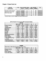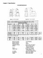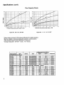
1
YCE FSVlOO and FSV200 Series
6 G eneral Purpose Solenoid Valves
@m
8mI
@fxI
8a
03fx
@m
03fxI
@m
03m
03mI
@fxI
8fxI
@aI
fl OMEGg Operator’s Manual
h An OMEGA Technologies Compsny
Servicing USA and Canada: Call OMEGA Toll Free
USA
One Omega Drive, Box 4047
Stamford, CT 06907-0047
Telephone: (203) 359-1660
FAX: (203) 359-7700
Canada
976 Bergar
Lava1 (Quebec) H7L 5Al
Telephone: (514) 856-6928
FAX: (514) 856-6886
Sales Service: l-800-826-6342
/ l-800-TC-OMEGASM
Customer Service: l-800-622-2378
/ l-800-622-BESTSM
Engineering Service: l-800-872-9436
/ l-800-USA-WHENSM
TELEX: 996404 EASYLINK: 62968934 CABLE OMEGA
Servicing Europe: United Kingdom Sales and Distribution Center
25 Swannington Road, Broughton Astley, Leicestershire
LE9 6TU, England
Telephone: 44 (1455) 285520
FAX: 44 (1455) 283912
The OMEGA Complete Measurement and
Control Handbooks & Encyclopedias
Temperature
Pressure, Strain & Force
Flow and Level
pH and Conductivity
Data Acquisition Systems
Electric Heaters
Environmental Monitoring
and Control
Call for Your FREE Handbook Request Form Today: (203)
CJSl194MAJBA
3599RUSH
Table of Contents
FSVIOO I FSV200 Series
General Purpose Solenoid Valve
Page
1 .1
1.2
1.3
1.4
1.5
Unpack ing
Desc ri p ti on
Fea t u r es
Ava il ab le M
Typ ica l App
1
..............................................................................................................
Chapter 1 Introduction
..................................................................................................................
.................................................................................................................
..................................................................................................................
ode ls .........................................................................................................
li ca ti ons .....................................................................................................
1
1
2
2
3
Chapter 2 Parts of the Solenoid Valve ......................................................................................
4
................................................................................................................
4
...........................................................................................
5
.......................................................................................................
6
..........................................................................................................
7
Chapter 3 Installation
Chapter 4 Troubleshooting Guide
Chapter 5 Spare Parts List
Chapter 6 Specifications
Notes
Chapter 1 Introduction
1 .l Unpacking
Remove the Packing List and verify that you have received all equipment, including the following (quantities in parentheses):
(1)
General Purpose Solenoid Valve
Operator’s Manual (1)
If you have any questions about the shipment, please call OMEGA Customer Service Department. When you receive the shipment, inspect the container and equipment for signs of damage. Note any evidence of rough handling in transit. Immediately report any damage to the
shipping agent.
NOTE
The carrier will not honor any claims unless all shipping
material is saved for inspection. After examining
and removing contents, save packing material and carton
in the event reshipment is necessary.
1.2 Description
The OMEGA@
FSVIOO
and FSV200
Series Two-Way Normally Closed Pilot Operated
Type Solenoid Valves cover most industrial applications. A two-way valve controls the flow of
fluid through a single passage.
It has two ports, an inlet and an outlet. A normally closed valve
does not pass fluid unless it is energized. There is fail safe positive valve closing in the event
of power failure that prevents flooding or overfilling.
These valves cover a wide range of operating pressures and temperatures. 5 PSI to 150 PSI
pressure and temperatures to 195°F affords broad application and tremendous flexibility.
long life bronze castings and waterproof coils insure performance consistency for a long life.
Since the valves are very rugged, they provide low incidence of down time and maintenance.
Minimum pressure drop internal design of this valve assures exceptional flow performance.
Piston-
The
1.3 Features
The
FSVlOOlFSV200
solenoid valves have the following features:
??
2-way Normally Closed
??
Pilot-Operated
??
Piston-Type
??
Bronze Construction
??
Variety of Voltages
??
Maximum Temperature of 195°F
??
Maximum Pressure 150 PSI
1.4 Available Models
OMEGA Engineering, Inc. has the following models with the following characteristics:
FSVI
00 Series for Water
Description
Part Number *
FSVI
01
FSV102
Solenoid Valve with
BUNA
N/EPDM Seal and
318” NPT Connector
Solenoid Valve with
BUNA
N/EPDM Seal and
l/2” NPT Connector
3/4” NPT Connector
FSVI
03
Solenoid Valve with
BUNA
N/EPDM
FSVI
04
Solenoid Valve with
BUNA
N/EPDM Seal and 1
FSVI
05
Solenoid Valve with
BUNA
N/EPDM Seal and 1.25”NPT Connector
Solenoid Valve with
BUNA
N/EPDM Seal and 1.50”NPT Connector
Solenoid Valve with
BUNA
N/EPDM Seal and 2.00”NPT Connector
FSV106
FSVI
07
* For DIN coil option, add suffix “-DIN”to the part number.
2
Seal and
.OO” NPT Connector
FSV200
Series for Light
Oils and Solvents
DescriDtion
Part Number *
FSV201
Solenoid Valve with Viton Seal and
3/8” NPT Connector
FSV202
Solenoid Valve with Viton Seal and
112” NPT Connector
FSV203
Solenoid Valve with Viton Seal and
3/4” NPT Connector
FSV204
Solenoid Valve with Viton Seal and 1
FSV205
Solenoid Valve with Viton Seal and 1.25 ”NPT Connector
FSV206
Solenoid Valve with Viton Seal and 1.50 ”NPT Connector
FSV207
Solenoid Valve with Viton Seal and 2.00 ”NPT Connector
* For DIN coil option, add suffix
“- DIN ” to the part number.
1.5 Typical Applications
Commercial Laundry Equipment and Facilities
Commercial Dishwashers, Bottlewashers, Pot/Pan Washers
Car
& Truck Wash Facilities
Irrigation Systems
Humidification
Water Treatment
Poultry Incubators/Watering Equipment
Industrial Maintenance, Repair, and Operation
.O” NPT Connector
Chapter 2 Parts of the Solenoid Valve
FSVlOO/200 Series
PLUNGER ASSEMBLY
PISTON SPRING
SPLtTRING(TEFLON,
PISTON BODY
SEAT WASHER NUT
Figure 2-1. 310”, l/2”, 314” NPT
SOLENOID SPRING
W AS HER
--SOLENOID
BONNET
BOHET G
PLUNGER ASSEMBLY
PISTON SPRING
SPLIT RING (TEFLON)
-PISTON BODY
Figure 2-2. I”, I%“, lYz”, 2” NPT
Chapter 3 Installation
Be sure to adhere to the following when installing your solenoid valve:
Arrow on valve body indicates direction of flow.
Apply wrench only on end of valve being connected;
(leverage on other valve parts can cause damage)
Install in horizontal position with solenoid vertical.
Make electrical connections in compliance with electrical code.
CAUTION
Be certain electric power is of the same voltage
and cycles as marked on solenoid.
4
Chapter 4 Troubleshooting Guide
Problem
Failure to open when
solenoid engergized
Failure to close when
solenoid de-energized
Leakage
1.
Possible Cause
Corrective Action
Low voltage at solenoid
(below 85% of rated
voltage)
Insure proper voltage at
solenoid
2. Solenoid failure
Check for excessive
voltage at solenoid
3.
Replace split rings
Worn rings
4. Pressure drop less
than 5 PSI
Increase pressure
differential to 5 PSI
5. Bonnet bent
Install new bonnet
6. Should have approximately 1
/I 6” gap in
split piston rings.
Trim as required
1. Piston Ring binding
between body bore
and piston
Remove piston and place
ring in groove, then insert
piston in body
2. Foreign matter lodged
on body seat
Remove piston and clean
out matter
3. Foreign matter
preventing plunger
from seating
Clean out foreign matter
at plunger seat hole
4.
Replace plunger
assembly
Plunger tip is broken
or badly worn
1. Plunger seat hole
eroded
3/8”, l/2”, & 314”
replace piston
l”, l-l/#“,
replace valve
2. Piston seat washer
takes a deep set
Caution:
Do not apply voltage to solenoid coil that has been removed from valve.
l-1/2”,
Replace seat washer
& 2”
Chapter 5 Spare Parts List
Coil with
l/2” NPT Conduit
outlet and
30” lead wires.
Fits all valve sizes.
Consult Factory for other voltages and coils with ground
wire.
3/8”*1/2”*3/&1”~1 W’*l x”92” NPT Connector Stvles
FSVI 00
7319503
Plunger Assembly
“0 ” Ring
Piston Assembly
Piston Seat Washer
6
7319503
7319503
73026
83192
83192
N/A
82224
82224
82224
83192
84048
76745
84571
76750
84518
7673801
1 85Oi9Oi
Teflon Split Piston Ring
(2 Req’d)
Piston Seat Washer
Piston Seat Washer
Same Parts as
7319503
,
8222301
Nut
FSVIOO
1 8222
8249801
2
86030
FSVZOO
Except Following Parts of Viton:
3ia” CL 112”
314”
74777
74777
N/A
7735504
84689
N/A
7730002
84688
I
1” & 11/4”
11/2”
74777
74777
87408
7643103
84794
85649
7646902
85614
2”
74777
85650
7647002
85612
Chapter 6 Specifications
FSVI OO/FSVZOO Series
ri
IT---- f’k
II
i-t
I
0
0
F
r-C--+
Figure 6-i.
Figure 6-2. 1”, 1?4”, I%“, CL 2”
3/W ’, 112”, 8 314”
FSVlOO: For fluids compatible with bronze, 430 F Stainless Steel, Ethylene Propylene, and Teflon
pei P
Size
r otCv
c Fa
ounm
Ther)aot c
r of
v FaC : ( et No
dl be usedshou
.
owfl
318”
3. 2
l/2"
1 'I
314”
3. 3
5. 7
8. 9
l-114"
l-112"
15
28
l-l/4"
7.25
3.29
l-112"
10.00
4.55
2"
39
son
i r pa ma co
318"
2.00
0.91
Weight
Lbs.
Kgs.
17.8
okes
t s ti Cen
5 PS
I PS 150
”
ot195F ° 32
OX( ) o Xt 90
il/( O ): 00
r et a W I andFSV
st ven
l So ) 200 FSV
(
120, s tt a W 23
t Va
s il co
M EPD
, onfl Te, ze onr B
200 FSV
( esi r Se ) onit - V
y Cha
it
owfl Capac
o r tef Re
esr gufi ve
o abo
r tef Re
el abt ve
o abo
r tef Re
Maximum Viscosity:
Minimum Pressure:
Maximum Presure:
Temperature Range:
Medium:
Power:
Wetted Parts:
: s uel
v VaC
: s oni s en mi D
t: ghi e W
s rt
1 'I
7.20
3.27
314"
3.50
1.59
112"
2.12
0.96
I
2"
13.75
6.25
Specifications (con?)
Flow Capacity Charts
450
100
90
400
80
350
70
300
E 6o
g5
E
k 250
0
.E 20 0
175
30 15 0
E 125
100
.E 4 0
h.
IA
30
20
;i
10
5
0
5 IO
20
30
40
60
SO
100
125
150
:8
05 10
20
30
40
60
80
100
125
Pressure Drop Across the Valve in PSI
Pressure Drop Across the Valve in PSI
Figure 64. l”, I%“, I%“, 2” NPT
Figure 6-3. 3/W ’, l/2”, 314” NPT
* Valves require minimum 5 PSI pressure differentialfor reliable operation.
* Must be installed in horizontal piping with solenoid in vertical position.
* Valve should be sized to flow requirement, not pipe size.
* Average closing time:
3/8”-314”
1-3 sec.,
I”-2”
2-5 sec.
, __ . _ .
. - _ --.
1 FSV202
FSV203
FSV204
FSV205
FSV206
FSV207
8
I
I
I
I
I
. .__
I
. .-__
I
_
_ . .--
.-
l/2
314
1 .oo
1.25
I .50
2.00
0.439 I
0.849
1.250
1.250
I 1.500
I
I
2.000 1
t
Viton
Viton
Viton
Viton
Viton
Viton
I
1
0.85
0.6-4.5 0.1-0.25
0.6-4.5 0.1-0.25
0.8-5.8
0.2-0.5
1.5-9
0.2-0.4
3.45
1.5-9.5 1 0.25-l
*0.005
*0.002
*0.002
kO.002
kO.002
150
Notes
WARRANTY
OMEGA warrants this unit to be free of defects in materials and workmanship and to give satisfactory service for a period of 13
months from date of purchase. OMEGA Warranty adds an additional one (1) month grace period to the normal
one (1) year product warranty to cover handling
and shipping time. This ensures that OMEGA ’s customers receive maximum coverage on each
product. If the unit should malfunction, it must be returned to the factory for evaluation. OMEGA ’s
Customer Service Department will issue an Authorized Return (AR) number immediately upon
phone or written request. Upon examination by OMEGA, if the unit is found to be defective it will
be repaired or replaced at no charge. However, this WARRANTY is VOID if the unit shows evidence
of having been tampered with or shows evidence of being damaged as a result of excessive corrosion; or current, heat, moisture or vibration; improper specification;
misapplication; misuse or
other operating conditions outside of
OMEGA’s control. Components which wear or which are
damaged by misuse are not warranted. These include contact points, fuses, andtriacs.
OMEGA is glad to offer suggestions on the use of its various products.
Nevertheless,
OMEGA only warrants that the parts manufactured by it will be as specified and free of
defects.
OMEGA MAKES NO OTHER WARRANTIES OR REPRESENTATIONS OF ANY KIND WHATSOEVER, EXPRESSED OR IMPLIED, EXCEPT THAT OF TITLE AND ALL IMPLIED WARRANTIES INCLUDING ANY WARRANTY OF MERCHANTABILITY AND FITNESS FOR A
PARTICULAR PURPOSE ARE HEREBY DISCLAIMED.
LIMITATION OF LIABILITY: The remedies of purchaser set forth herein are exclusive and
the total liability of OMEGA with respect to this order, whether based on contract, warranty, negligence, indemnification, strict liability or otherwise, shall not exceed the
purchase price of the component upon which liability is based. In no event shall
OMEGA be liable for consequential, incidental or special damages.
Every precaution for accuracy has been taken in the preparation of this manual; however, OMEGA
ENGINEERING, INC. neither assumes responsibility for any omissions or errors that may appear
nor assumes liability for any damages that result from the use of the products in accordance with
the information contained in the manual.
SPECIAL CONDITION: Should this equipment be used in or with any nuclear installation or activity,
purchaser will indemnify OMEGA and hold OMEGA harmless from any liability or damage whatsoever arising out of the use of the equipment in such a manner.
RETURN REQUESTS / INQUIRIES
Direct all warranty and repair requests/inquiries
the bMEGA
to ENGINEERING Customer Service
Department. BEFORE RETURNING ANY PRODUCT(S) TO OMEGA, PURCHASER MUST OBTAIN AN
AUTHORIZED RETURN (AR) NUMBER FROM OMEGA ’S CUSTOMER SERVICE DEPARTMENT (IN
ORDER TO AVOID PROCESSING DELAYS). The assigned AR number should then be marked on the
outside of the return package and on any correspondence.
FOR WARRANTY RETURNS, please have the
following information available BEFORE contacting OMEGA:
1. PO. number under which the product was
PURCHASED,
2. Model and serial number of the product
under warranty, and
3. Repair instructions and/or specific problems relative to the product.
FOR NON_WARRANTY REPAIRS OR CALIBRATION, consult OMEGA for current repair/
calibration charges. Have the following
information available BEFORE contacting OMEGA:
1. P.O. number to cover the COST of the
repair/calibration,
2. Model and serial number of product, and
3. Repair instructions and/or specific problems
relative to the product.
OMEGA’s policy is to make running changes, not model changes, whenever an improvement is possible. This affords
our customers the latest in technology and engineering.
OMEGA is a registered trademark of OMEGA
INC. ENGINEERING,
0 Copyright 1994 OMEGA ENGINEERING, INC. All rights reserved. This documentation may not be copied, photocopied,
reproduced, translated, or reduced to any electronic medium or machine-readable form, in whole or in part, without prior
written consent of OMEGA ENGINEERING, INC.
Where Do I Find Everything I Need for
Process Measurement and Control?
OMEGA...Of Course!
TEMPERATURE
D
aI
E
al
Thermocouple, RTD & Thermistor Probes, Connectors, Panels & Assemblies
Wire: Thermocouple, RTD & Thermistor
Calibrators & Ice Point References
Recorders, Controllers & Process Monitors
Infrared Pyrometers
PRESSURE/STRAIN FORCE
B Transducers & Strain Gages
m Load Cells & Pressure Gauges
m Displacement Transducers
@ Instrumentation & Accessories
FLOW/ LEVEL
m Rotameters, Gas Mass Flowmeters
& Flow Computers
m Air Velocity Indicators
m Turbine/Paddlewheel Systems
B Totalizers & Batch Controllers
H/CONDUCTIVITY
b pH Electrodes, Testers & Accessories
D Benchtop/Laboratory Meters
m Controllers, Calibrators, Simulators & Pumps
@’ Industrial pH & Conductivity Equipment
DATA ACQUISITION
m Data Acquisition and Engineering Software
@ Communications-Based Acquisition Systems
w Plug-in Cards for Apple, IBM & Compatibles
D Datalogging Systems
D Recorders, Printers & Plotters
HEATERS
B Heating Cable
w Cartridge & Strip Heaters
w Immersion & Band Heaters
m Flexible Heaters
D Laboratory Heaters
ENVIRONMENTAL MONITORING AND CONTROL
Metering & Control Instrumentation
Refractometers
Pumps & Tubing
Air, Soil & Water Monitors
Industrial Water & Wastewater Treatment
pH, Conductivity & Dissolved Oxygen Instruments
9lM48
/ 1194