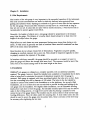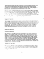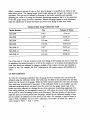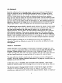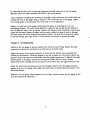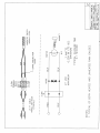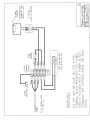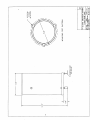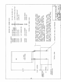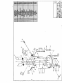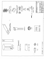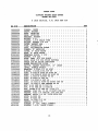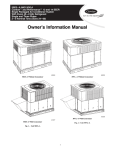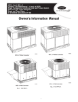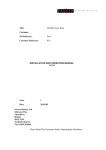
1
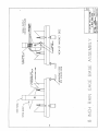
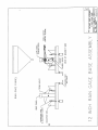
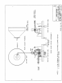
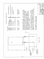
&E RG-2500 Series
a Tipping Bucket Rain Gauge
03-I
8
Operator% ManMal
Servicing USA and Canada: Call OMEGA Toll Free
Canada
USA
One OmegaDrive, Box 4047
Stamford, CT 06907-0047
Telephone: (203) 359-1660
FAX: (203) 359-7700
976 Bergar
Lava1 (Quebec)H7L5Al
Telephone: (514) 856-6928
FAX: (514) 856-6886
Sales Service: l-800-826-6342/ l-BOO-TC-OMEGASM
Customer Service: l-800-622-2378/ l-BOO-622-BESTSM
Engineering Service: l-800-872-9436/ l-BOO-USA-WHENSM
TELEX: 996404 EASYLINK: 62968934 CABLE: OMEGA
Servicing Europe: United Kingdom Sales and Distribution Center
25 Swannington Road, Broughton Astley, Leicestershire
LE9 6TU, England
Telephone: 44 (1455) 285520FAX: 44 (1455) 283912
The OMEGA Complete Measurement and
iControl Handbboks & Encyclopedias
v
r/
V Data Acquisition Systems
1/ Electric Heaters
r/ Environmental Monitoring
and Control
Temperature
Pressure, Strain & Force
P Flow and Level
v pH and Conductivit y
Call for Your FREE Handbook Request Form Today: (203) 3591RUSH
I
MSSO395FVRlB
yI
Y
i
Unpacking Instructions
Remove the Packing List and verify that you have received all equipment, including the following
(quantities in parentheses):
RG-2500 Tipping Bucket Rain Gauge (1)
Operator’s Manual (1)
If you have any questions about the shipment, please call the OMEGA Customer Service
Department.
When you receive the shipment, inspect the container and equipment for signs of damage. Note
any evidence of rough handling in transit. Immediately report any damage to the shipping agent.
The carrier will not honor damage claims unless all shipping material is saved for
inspection. After examining and removing contents, save packing material and
carton in the event reshipment is necessary.
Y
TABLE OF CONTENTS
1.
Chapter 1 Introduction .........................................
1.1 General Description ................... ‘ ................. 1
.1
1.2 Specifications.......................................
Chapter 2 Installation .......................................... 2
2.1 Site Requirements ..................................... 2
2.2 Installation.......................................... 2
Chapter 3 Operation
. . . . . . . . . . . . . . , . . . . . . . . . . . . . . . . . . . , , . . . . . . .3
Chapter 4 Calibration..........................................
4.1 Factory Calibration ....................................
4.2 Calibration Procedure...................................
4.3 Field Calibration ......................................
4.4 Adjustments .........................................
Chapter 5 Maintenance
Chapter 6 Troubleshooting
. . . . . . . . . . . . . . . . . . . . . . . . . . . . . . . . . . . . . . . . .6
. . . . . . . . . . . . . . . . . . . . . . . . , . . . . , . . . . . . . . .6
3
3
3
4
4
.
Chapter 1: Introduction
1.1 General Description
The RG-2500 Series consists of two high quality rain gauges, Models RG-2500RGand
2500-12. Model RG-2500 features a standard eight-inch diameter orifice, while the Model
RG-2500-12 has a twelve-inch diameter orifice. Both gauges have been designed with high
grade materials and have been built to provide years of trouble-free operation.
Each of the two gauges consists of a main collection funnel, an outer cover, an internal
funnel, a tipping bucket and magnetic switch assembly, a base, and mounting feet with
leveling adjustments.
Electrically heated versions of both gauges can be provided for use in cold climates, for
measuring frozen precipitation such as snow and sleet. The electrically heated versions
include the features listed above plus a heater element, a thermostat, a fuse holder and fuse,
and associated wiring and terminal blocks. The model numbers for the heated rain gauges are
RG-2500E andRG-2500E-12.
1.2 Specifications
Capacity: Unlimited
Orifice:
RG-2500: 8” (20 cm)
RG-2500-12: 12” (30 cm)
Calibration: 0.01” per tip (0.25 mm), others on request
Accuracy: + 1% for 1 to 3 inches per hour, + 3% for 0 to 6 inches per hour
Switch: Magnetic reed, SPST N.O., 10 Watts, 200 Vdc, 0.5 A max
Dimensions:
RG-2500: 8” x 17 ”
RG-2500-12: 12” x 20 ”
Weight/Shipping:
RG-2500: 7lbs/12 lbs
RG-2500-12: 14lbs/18 lbs
Optional Accessories:
Wind Screen, Alter Type
Event Recorder, Drum Chart
Calibrator Bottle
Digital Event Counter
Model RG-952
Model RG-6113-A
Model RG-2595
Model RG-2596
1
Chapter 2: Installation
2.1 Site Requirements
The location of the rain gauge is very important to the successful operation of the instrument.
The most accurate measurements are made in relatively sheltered areas protected from
gusting and turbulent winds. Openings in orchards or a grove of trees offer the best exposure
for the rain gauge. Fences and other structures can help serve as a wind break as long as
they are not too tall. In areas that are open with no nearby structures, a wind screen such is
recommended to protect against wind effects.
Generally, the heights of objects near a rain gauge should be proportional to the distance
away from the gauge. The distance of a nearby object should always be at least twice the
height of the object above the gauge.
Wind effects on catch losses are more pronounced during snow storms than during a rain
storm. A wind screen is generally not used at locations where snowfall constitutes less than
20% of the mean annual precipitation.
Good locations do not always remain free of obstructions. Vegetation can grow quickly,
changing an excellent exposure into a poor one. Sites should be inspected regularly in order
to properly maintain the exposure of the gauge.
In locations with heavy snowfall, the gauge should be mounted on a support or tower to
place the gaugewell above the average local snow level. The exposure would be best if the
tower wereto be located among trees of the same height as the tower.
2.2 Installation
OMEGA@ rain gauges are shipped as a complete assembly with no additional assembly
required. ‘The gauge, however, should be installed onto a platform or foundation that
fairly
is
close to being level to minimize the amount of adjustment required after the gauge is
mounted. Each gauge is equipped with three mounting brackets that also serve as feet. Each
3/8 inches. The holes in the feet should be
foot has a mounting hole with a diameter of
matched to anchor bolts located in the foundation or on the platforms. for severely tilted
foundations, use a set of three hex nuts on each bolt to provide leveling and locking of the
rain gauge onto the foundation. For slightly tilted foundations, use the adjustable leveling
knobs above each foot to level the gauge. An internally mounted spirit level may be used to
assist in the leveling process. A rough level can be taken by placing a carpenter ’s level
across the top of the gauge funnel. Flat washers may be used as shims to help correct large
leveling differences. Place the shims under the mounting feet. A lock washer and a hex nut
should be used to secure the gauge onto the anchor bolts. Some correction of the level may
be necessary after tightening the hex nuts.
2
The leveling knobs located above the mounting feet are secured using
allen head set screws.
These set screws must be loosened before the knobs can be moved. The set screws are
accessible from the sides of the base. Re-tighten the set screws after leveling the gauge to
help ensure that the level adjustment will not shift due to loose screws.
The gauge may be installed with the outer cover on or with it removed. Three screws hold
the outer cover in place. Take out these three screws to remove the cover. Carefully remove
the cover, avoiding hitting any of the internal rain gauge parts. Some of the moving parts are
tied down to prevent movement and possible damage during shipping. Remove any tape,
plastic ties, foam inserts, or other objects used to keep the tipping buckets from moving. The
bucket assembly should move easily with the packing materials removed.
Chapter 3: Operation
The rain gauge operation is relatively simple.
As rain is collected by the eight-inch diameter
orifice, the rain drops are directed down through the funnel and into the bucket assembly. As
soon as the bucket has collected enough rain to represent 0.01 inches (or 0.25 mm) of rain,
the bucket tips. The rain drains out through the drain collection tubes and the magnet is
moved past the reed switch. The reed switch closes momentarily, making an electrical
contact that is used in conjunction with electronic counting and recording instruments.
Chapter 4: Calibration
4.1 Factory Calibration
Each rain gauge is thoroughly tested before being shipped to the customer. A measured
amount of water is passed through the rain gauge to give an expected number of counts
according to the diameter of the orifice. The bucket calibration posts have screws that are
adjusted until the correct number of counts are achieved with repeated testing. The exact
number of counts or nearly the exact number are recorded for each gauge. As long as the
number of counts is within the specified accuracy of the gauge, the calibration will be
accepted. The calibration of the gauge should not change during shipping unless the gauge
becomes damaged. Checking of the gauge calibration may be made after the gauge has been
installed to ensure the accuracy of the data.
4.2 Calibration Procedure
The rain gauge calibration may be checked using a graduated burette or cylinder. Wet the
gauge thoroughly allowing water to flow through the gauge before beginning the test. The
the gauge
wetting of the gauge helps compensate for water that may adhereportions.of
to
causing some error in the counts.
3
Allow a measured amount of water to flow into the gauge at a specified rate. Refer to the
table shown below. The tipping bucket should begin tipping and will give the number of tips
calculated. The tips may be counted by listening to the bucket assembly and manually
tabulating the count or by using the electronic monitoring equipment that is to be connected
to the rain gauge during its normal operation. Should the gauge appear to need adjustment,
make the adjustments in small increments and retest each change at least three times.
Standard Rain Gauge Calibration Table
Tip
Volume of Water
RG-2500
0.01”
8.24 ml
RG-2500
0.05”
41.20 ml
RG-2500
0.2 m m
6.48 ml
RG-2500
0.5 mm
16.215 ml
RG-2500-12
0.01”
18.53 ml
RG-2500-12
0.2 mm
14.60 ml
RG-2500-12
0.5 mm
36.48 ml
Model Number
Use a flow rate of 1 ml per second to avoid over filling of the buckets and loss of water due
to splashing. the desired accuracy is~3% of the volume at 1 to 6 inches of precipitation per
hour. Best results are obtained by taking a multiple of the volume of water and counting a
number of tips. For example, the 0.01 ” calibration at 100 counts requires 824 milliliters of
water.
4.3 Field Calibration
To verify the rain gauge calibration after the gauge has been installed, best results may be
obtained using the calibration bottle. The bottle may be filled to the specified level and then
placed into the funnel of the gauge. While the bottle slowly empties the water into the funnel
other tasks may be performed if necessary. If the calibration bottle is not available, use any
calibrated measuring device and slowly pour the water into the gauge. Keep track of the
bucket tips either manually or through the use of the electronic monitoring equipment. For
45% since the control of the methods is
field testing methods, use an expected accuracy of
not as good as when the testing is done in the laboratory. The total number of tips should
equal the amount of water poured into the gauge, divided by the calibrated number of tips
per the number of milliliters of water shown in the table. For example, a quart of water is
fof a quart of
equal to 946.3 milliliters. So for a 0.01 ” calibration, the number of counts
water should be 946.3 t 8.24 = 114.8.
4.4 Adjustments
Should the calibration of the rain gauge appear to be incorrect and in need of adjustment,
change the heights of the two calibration posts adjustment screws. To change the screw
heights, loosen the nut on the top of the post that locks the screw into place. Rotate each
screw by a small amount only and recheck the calibration for the new screw positions.
Empty all water from the buckets but do not dry off the buckets. The exact amount of water
needed for a single bucket tip may be added into a bucket to see how closely the calibration
post screw may be to the position needed for the bucket to tip. After obtaining this point of
adjustment, tighten down the locking nuts on the calibration posts screws and test the gauge
using a large amount of water at the proper flow rate and count the total number of tips.
The calibration post screws should be adjusted upward whenever the amount of water needed
to cause the bucket to tip is more than the amount shown in the calibration table. Whenever
less water than the amount in the table causes the bucket to tip, the screws need to be
adjusted downward. The two sides of the bucket assembly should generally be at about the
same calibration adjustment. There may be situations where one of the bucket calibration
post screws has moved and is off more than the other screw. In this situation the single tip
amount of water calibration method may be better for correcting the one side of the bucket to
match the other side more closely. Do not dry the buckets during the adjustment procedure.
Carefully tighten the locking nuts on the calibration post screws after completing the
adjustments. Recheck the calibration to ensure that the screws have not shifted as the nuts
were tightened.
Chapter 5: Maintenance
Annual maintenance of the rain gauge is recommended. Cleaning of the gauge more often
may be necessary in areas where there is a lot of leaves, dust, and other debris that falls into
the gauge. Cleaning includes removal of the outer cover, rinsing and drying off of the
buckets, cleaning of the drain holes, and removal of debris from all of the screens. the outer
and inner funnels should also be rinsed and dried off to remove dirt, dust and insects.
The gauge calibration should be tested during the maintenance procedure and adjusted if
necessary. If there is a regularly scheduled maintenance of the gauge on a monthly basis, the
calibration can be tested less often.
At least once a year, or if possible, after six months of heavy operation, a drop of light
machine oil should be placed onto the bearings. Do not over-oil and wipe off any excess oil.
The electrical output of the gauge should be tested to ensure that the magnet and switch
assemblies are still functioning. The switch used in the gauge is a momentary contact,
normally open, single pole switch. Test the switch using an ohmmeter, buzzer, or counter, or
5
by observing the data of the monitoring
equipmen normally connected to the rain gauge.
Manually move the bucket assembly and look for he switch closure.
ge, replace the outer cover and funnel and
Upon completion of testing and cleaning of the1ga
recheck the level of the gauge using a carpenter ’s level across the top of the gauge. Adjust
the leveling knobs at the mounting feet if the level is out of adjustment.
Replace or repair any of the gauge components that appear to be damaged or are not
functioning properly. The outer funnel should be replaced if the rim has become dented or
bent. Repaint the outer cover as needed. Replace any hardware that is missing or has become
rusted and corroded. Inspect the signal and any power cables for signs of wear or damage
that may expose the wires. Replace the cables as needed. Use wire ties to secure the cables
to prevent damage from high winds. For best results, use conduit to protect the cables.
Chapter 6: Troubleshooting
Failure of the rain gauge to operate usually is the result of loose wiring. Inspect the cable
connections to ensure the connections are solid and are correctly made.
Inspect the motion of the bucket assembly to ensure that the buckets move smoothly and
without any interference. Check the magnet to see that it passes over the switch without any
physical contact and that the switch closes when the magnet passes over it. Should the bucket
motion appear to be sticky, remove the bearings and inspect them for wear. Annual
replacement of the bearings may be necessary in areas where there are high amounts of rain.
Check the inlet funnel and funnel screens for blockage whenever the rain gauge operation
appears to be low or missing. Also inspect the drain tubes for debris that may interfere with
the bucket motion.
Whenever the rain gauge output appears to be too high, check to ensure that the gauge is still
level and recheck the calibration.
6
--
r
Z-PI N
TERMINAL
BLOCK
MAGNETIC SWITCH
25 FT CABLE
MODEL 330-022
( TYP IC A L)
( NORMALLY
0
DIODE
__
_
__
OPEN)
------- --
2-PI N
TB
RED
&w
DIODE
*
SWITCH
BLK
IL7
-0
BLK
MAGNET
N.O.
27 VD C
MAXIMUM
3 WATT S
0.25A @ 175 VD
MAXIMU M
C
TYPICAL CLOSURE TIME
0.1 SECON D
NOTES:
1. TYPICAL OF BOTH HEATED AND UNHEATED RAIN GAUGES
.
w -
t
25x
CASE
GROUND /ib
4-PI N
TERMINAL
BLOC K
10
FUSE
5 AM P
SLO BLO
25 FT POWER CORD
18 AWG, SVT
-
34 OHMS
FIRE ROD HEATER
400 W @ 115 VA
C
WARN’.ING
115 VAC WILL BE ALIVE ON THE 4-PI
N
TERMINAL BLOCK WHENEVER THE POWE
R
CORD IS PLUGGED INTO A POWER OUTLET
.
T!iE RAI N
TERMINALS ARE EXPOSED INSIDE
GAUGE.
0347
;
o
\,
8.0”
------I
MOUNTING FEET PAT
WTH LEVELER
L(oo.
\
BY
0.7t:
0.
..‘.
-. .-
2C
5”
MOUNTING FEET PAT
+
2.0”
t
MOUNTING FOOT
WlTH LEVELER
uoo. u
-
\<
By
OAIE
a
a
I=
RAIN GAGE FUNNEL
INNER FUNNEL
7
CALIBRATION POST
SCREW
& ADJUSTMENT
2 PIN SIGNAL
f- TERMINAL BLOCK
TIPPING BUCKET
\
SIGNAL OUTPUT
CONTACT CLOSURE
COLLECTION TUBE
FOOJI~JE
MTH LEVELER
12 INCH RAIN GAGE BASE ASSEMBL
I
Y
1,
OAIE
,/
THERMOS ‘TAT
%
RAIN GAGE FUNNE
L\
d_
BOTTOM VIEW
SIDE VIEW
(WIRING OMITTED)
W lT H LE
VIEW OF MAGNET SIDE
M LER
RAIN GAGE BASE ASSEMBLY
E
NOTES
- 1. 4 PIN TERMINAL BLOCK IS POSITIONED BEHIND HEATER
2. OUTER COVER NOT
SHOWN. ’
nn
.
1
UOD. U
REVISED AUG 1994
tL
MOUNTING BOLT ASSEMBLY DETAIL
PART NUMBEfiS
RAI
72270101
72341501
7231750 2
5/16 HEX NUT
5/16 LOCK WASHER
5/16 FLAT WASHER
g
7231750
5/16 FLAT WASHER
v
2
72270101
5/16 HEX NUT
72270101
5/16 HEX NUT
&
LOC
HEIG
LOC
7250000
0
5/16 THREADED ROD
7231760
2
3/8 FLAT WASHER
&
ANC
5/16 HEX NUT
&
A
72270101
I
FOR INSTALLATIONS
USING A 24” ALTER ST
WIND SCREEN THIS HEIGHT MUST BE ADJUSTED
SO THAT THE TOP EDGE OF THE RAIN GAGE
IS WITHIN 1 INCH OF THE TOP EDGE OF THE
WIND SCREEN LEAVES. SET BOLT HEIGHT
PRIOR TO POURING CONCRETE FOUNDATION.
TYPICAL LENGTH OF THREADED ROD WILL BE
APPROXIMATELY 24 INCHES.
SET HEIGHT ADJUSTING NUTS FOR ALL THREE
OF THE RAIN GAGE MOUNTING FEET UNTIL THE
RAIN GAGE IS LEVEL ACCORDING TO THE SPIRI
BUBBLE LEVEL LOCATED ON THE RAIN GAGE B
FOR WOODEN PLATFORMS THERE
ARE EXTRA NUTS AND WASHERS.
I
TYPICAL VIEW
nRE
K
Yoo.
By
1
DATE
MOUNTING BOLT ASSEMBLY DETAIL
PART NUMBERS
c
~
20.75”
12 INCH
RAIN GAGE
I
7227010 1
7234150 1
7231750 2
7231750 2
5/16 HEX NUT
5/16 LOCK WASHER
5j16 FLAT WASHER
@
&
5/16 FLAT WASHER
F
7227010 1
5/16 HEX NU T
7227010 1
5/16 HEX NUT
&I
RAIN
LOC
HEIG
LOC
7250000
0
5/16 THREADED ROD
7231760
2
3/8 FLAT WASHER
&
ANC
5/16 HEX NUT
&
ANC
7227010 1
I
TYPICAL OF THREE EAC
!
15.25” APPROX
t
GROUND LEVEL
(APPROX)
12” APPROk
I
7r
II
II
II
-#
Ll
CONCRETE
FOUNDATION
TYPICAL VIEW
II
FOR INSTALLATIONS USING A 36” ALTER STYLE
WIND SCREEN THIS HEIGHT MUST BE ADJUSTED
SO THAT THE TOP EDGE OF THE RAIN GAGE
IS WITHIN 1 INCH OF THE TOP EDGE OF THE
WIND SCREEN LEAVES. SET BOLT HEIGHT
PRIOR TO POURING CONCRETE FOUNDATION.
TYPICAL LENGTH OF THREADED ROD WILL BE
APPROXIMATELY 30 INCHES.
SET HEIGHT ADJUSTING
,NUTS FOR ALL TH
OF THE RAIN GAGE MOUNTING FEET UNTIL THE
RAIN GAGE IS LEVEL ACCORDING TO THE SPIR
BUBBLE LEVEL LOCATED ON THE RAIN GAGE B
ANCHOR NUT AND
3/8 WASHER.
’
"RE R
K
UOD. U
BY
\
,
DATE
I
/--
\\
I\\
I’,\ \ I
I
1’1
S I LVER
TAPE
THERMOSTAT BRACKET
(SHOWN IN INVERTED
00 ::
INSULATING
FOIL
25 - x11"
i
POUTION)
42
i
\
1
2 - x11”
C
FIREROD HEATE R
THERMOSTAT
HEAT S
I NK TUBE
CLAMP
PLUG
-+
SOCKET
W ARN
I NG LABEL
DRAWING NOT TO SCALE
\
PARTS LIST
TIPPING BUCKET RAIN GAUGE
MODEL RG-2500
8 INCH ORIFICE, 0.01 INCH PER TIP
NL P/N
DESCRIPTION
10000006
10000007
10000008
10000009
1000001 1
1000002 4
1000002 6
1000002 7
1000002 8
1000002 9
1000003 0
1000011 6
1000013 9
1000014 0
2105140 1
2500000 2
2800040 2
4080330 1
4190060 0
4631150 1
5100180 2
6480200 1
7101000 0
7113110 2
7208210 2
7208400 2
7212200 3
7214630 1
7214820 1
7218800 2
7218800 3
7221140 1
7222520 1
7224630 2
7230030 1
7231050 2
7234140 1
7245060 1
7245060 2
7245060 3
7260000 0
A10078 5
A10078 6
FUNNEL.INNER
....................
SHAFT, BUCKET ....................
...................
FOOT, LEVELING
...................
KNOB, LEVELING
BRACKET, BUCKET ...................
BUCKET, 0.01" ....................
..............
SCREEN, l-5/8 DRAIN TUBE
OTY
...............
HOLDER, MAGNET
3/8 DIA
..................
COVER, MAGNET ARM
..................
TUBE, COLLECTION
...............
POST, CALIBRATION SCREW
.................
FUNNEL, 8" ANODIZED
................
COVER, 8" RAIN GAUGE
.................
8"
RAIN
GAUGE
BASE ,
................
TERMINAL BLOCK, 2 PIN
MAGNET, 3/8DIA ...................
..............
.875 DIA BLACK
PLUG, VENT
..........
PLUG, HOLE S/8 DIA NYLON NATURAL
............
SPADE LUG #6 NYLON INSULATED
...............
SURGE PROTECTION DIODE
SWITCHp M RRQXIMITY, 12" LEAD
S .........
..............
LEVEL, BUBBLE SPIRIT
SS'MiNI .............
0.25x0.375
BEARING,
E-RING,
1/4IDX.210X.O29 S S
SCRU, 6-32X3/8 BIND HD SLOT
S'S ........................
..........
SCRU, 1/4-20X5/8 BIND HD SLOT SS
.............
SCRU, 2-56X3/8 SOCKET HD SS
...............
SCRU, 8-32X3/16 SET S
S
SCRU, l/4-20)31/4 SET S S ...............
........
SCRU, 10-32X1/2 BUTN HD SOCKT CAP SS
..........
SCRU, 10-32X1/2 HEX WASHER HD SS
.............
4
NUT, 6-32 HEX SS 5/16X7/6
.....
.
8
NUT, 8-32 HEX SS 11/32X1/
NUT, ACORN 8-32 HEX SS .330X:37
5
13/64X7/16X:O;l' : ....................
WASHER, FLAT NO. 10 SS
........
WASHER, FLAT
l/4 TEFLON .25X.50X.062
.........
WASHER, SPLIT
l/4 SS .255X.493X.062
STUD, 6-32X2SS.. .................
STUD, 8-32X2SS.. .................
................
S
STUD, 10-32X1-1/2 S
WRENCH, ALLEN1/8 ..................
SCREEN, 2" DIA, SMALL
FUNNELL ............
.............
SCREEN, 7-S/8, LARGE FUNNEL
15
.
.
.
.
.
.
.
.
.
.
.
.
.
.
.
.
.
.
.
.
.
.
.
.
.
.
.
.
.
.
.
.
.
.
.
.
.
.
.
.
1
1
3
3
1
1
2
1
1
2
2
1
1
1
1
1
3
1
6
1
1
1
2
2
2
2
3
5
3
2
3
2
2
2
5
2
2
1
2
3
1
1
1
Y
16
WARRANTY
OMEGA warrants this unit to be free of defects in materials and workmanship and to give satisfactory service for a period of 13 months from date of purchase. OMEGA Warranty adds an additional one (1) month grace period to the normal one (1) year product warranty to cover handling
and shipping time. This ensures that OMEGA ’s customers receive maximum coverage on each
product. If the unit should malfunction, it must be returned to the factory for evaluation. OMEGA ’s
Customer Service Department will issue an Authorized Return (AR) number immediately upon
phone or written request. Upon examination by OMEGA, if the unit is found to be defective it will
be repaired or replaced at no charge. However, this WARRANTY is VOID if the unit shows evidence
of having been tampered with or shows evidence of being damaged as a result of excessive corrosion; or current, heat, moisture or vibration; improper specification; misapplication; misuse or
other operating conditions outside of OMEGA ’s control. Components which wear or which are
damaged by misuse are not warranted. These include contact points, fuses, andtriacs.
OMEGA is glad to offer suggestions on the use of its various products. Nevertheless,
OMEGA only warrants that the parts manufactured
by it will be as specified and free of
defects.
OMEGA MAKES NO OTHER WARRANTIES OR REPRESENTATIONS OF ANY KIND WHATSOEVER, EXPRESSED OR IMPLIED, EXCEPT THAT OF TITLE AND ALL IMPLIED WARRANTIES INCLUDING ANY WARRANTY OF MERCHANTABILITY
AND FITNESS FOR A
PARTICULAR PURPOSE ARE HEREBY DISCLAIMED.
LIMITATION OF LIABILITY: The remedies of purchaser set forth herein are exclusive and
the total liability of OMEGA with respect to this order, whether based on contract, warranty, negligence, indemnification, strict liability or otherwise, shall not exceed the
purchase price of the component upon which liability is based. In no event shall
OMEGA be liable for consequential, incidental or special damages.
Every precaution for accuracy has been taken in the preparation of this manual; however, OMEGA
ENGINEERING, INC. neither assumes responsibility
for any omissions or errors that may appear
nor assumes liability for any damages that result from the use of the products in accordance with
the information contained in the manual.
SPECIAL CONDITION: Should this equipment be used in or with any nuclear installation or activity,
purchaser will indemnify OMEGA and hold OMEGA harmless from any liability or damage whatsoever arising out of the use of the equipment in such a manner.
RETURN REQUESTS / INQUIRIES
Direct all warranty and repair requests/inquiries to the OMEGA ENGINEERING Customer Service
Department. BEFORE RETURNING ANY PRODUCT(S) TO OMEGA, PURCHASER MUST OBTAIN AN
AUTHORIZED RETURN (AR) NUMBER FROM OMEGA ’S CUSTOMER SERVICE DEPARTMENT (IN
ORDER TO AVOID PROCESSING DELAYS). The assigned AR number should then be marked on the
outside of the return package and on any correspondence.
FOR WARRANTY RETURNS, please have the
following information available BEFORE contacting OMEGA:
1. P.O. number under which the product was
PURCHASED,
2. Model and serial number of the product
under warranty, and
3. Repair instructions and/or specific problems relative to the product.
FOR NON-WARRANTY REPAIRS OR CALIBRAm, consult OMEGA for current repair/
calibration charges. Have the following information available BEFORE contacting OMEGA:
1. P.0. number to cover the COST of the
repair/calibration,
2. Model and serial number of product, and
3. Repair instructions and/or specific problems
relative to the product..
OMEGA ’s policy is to make running changes, not model changes, whenever an improvement is possible.
our customers the latest
This affords
in technology and engineering.
OMEGA is a registered trademark of OMEGA ENGINEERING, INC.
Q Copyright ‘I995 OMEGA ENGINEERING, INC. All rights reserved. This documentation may not be copied, photocopied,
reproduced, translated, or reduced to any electronic medium or machine-readable form, in whole or in part, without prior
written consent of OMEGA ENGINEERING, INC.
Where Do I Find Everything I Need for
Proce !ss Measurement and Control?
OMEGA...Of Course
!
TEMPERATURE
@’ Thermocouple, RTD
& Thermistor Probes, Connectors, Panels & Assemblies
@’ Wire: Thermocouple, RTD & Thermistor
w Calibrators & Ice Point References
@ Recorders, Controllers & Process Monitors
@ Infrared Pyrometers
PRESSURE/STRAIN FORCE
m Transducers & Strain Gages
m Load Cells & Pressure Gauges
D Displacement Transducers
@ Instrumentation & Accessories
FLOW/ LEVEL
m Rotameters, Gas Mass Flowmeters
& Flow Computers
m Air Velocity Indicators
5 Turbine/Paddlewheel Systems
D Totalizers & Batch Controllers
H/CONDUCTIVITY
& pH Electrodes, Testers & Accessories
@ BenchtopjLaboratory Meters
@ Controllers, Calibrators, Simulators & Pumps
m Industrial pH & Conductivity Equipment
DATA ACQUISITION
m Data Acquisition and Engineering Software
@ Communications-Based Acquisition Systems
D Plug-in Cards for Apple, IBM & Compatibles
@’Datalogging Systems
D Recorders, Printers & Plotters
HEATERS
5 Heating Cable
m Cartridge & Strip Heaters
D Immersion & Band Heaters
m Flexible Heaters
@ Laboratory Heaters
ENVIRONMENTAL MONITORING AND CONTROL
D Metering & Control Instrumentation
m Refractometers
@ pumps & Tubing
@ Air, Soil & Water Monitors
@’ Industrial Water & Wastewater Treatment
m pH, Conductivity & Dissolved Oxygen Instruments
M2234/0395