1
OKI
JOB60851 Starter Kit
User’ s Manual
Version 1.07 (July 27, 2000)
Oki Electric Industry Co., Ltd..
Technocollage Inc
OKI
NOTICE
1. The information contained herein can change without notice owing to product and/or technical
improvements. Before using the product, please make sure that the information being referred to is
up-to-date.
2.
The outline of action and examples for application circuits described herein have been chosen as an
explanation for the standard action and performance of the product. When planning to use the
product, please ensure that the external conditions are reflected in the actual circuit, assembly, and
program designs.
3.
When designing your product, please use our product below the specified maximum ratings and
within the specified operating ranges including, but not limited to, operating voltage, power
dissipation, and operating temperature.
4.
Oki assumes no responsibility or liability whatsoever for any failure or unusual or unexpected
operation resulting from misuse, neglect, improper installation, repair, alteration or accident,
improper handling, or unusual physical or electrical stress including, but not limited to, exposure to
parameters beyond the specified maximum ratings or operation outside the specified operating
range.
5.
Neither indemnity against nor license of a third party’s industrial and intellectual property right, etc.
is granted by us in connection with the use of the product and/or the information and drawings
contained herein. No responsibility is assumed by us for any infringement of a third party’s right
which may result from the use thereof.
6.
The products listed in this document are intended for use in general electronics equipment for
commercial applications (e.g., office automation, communication equipment, measurement
equipment, consumer electronics, etc.). These products are not authorized for use in any system or
application that requires special or enhanced quality and reliability characteristics nor in any system
or application where the failure of such system or application may result in the loss or damage of
property, or death or injury to humans.
Such applications include, but are not limited to, traffic and automotive equipment, safety devices,
aerospace equipment, nuclear power control, medical equipment, and life-support systems.
7.
Certain products in this document may need government approval before they can be exported to
particular countries. The purchaser assumes the responsibility of determining the legality of export
of these products and will take appropriate and necessary steps at their own expense for these.
8.
No part of the contents contained herein may be reprinted or reproduced without our prior
permission.
Copyright 2000 Oki Electric Industry Co., Ltd.
Contents
1. Introduction ............................................................................ 1-1
1-1. Cheking Packing List ...................................................................................1-2
1-2. Host Environment ........................................................................................1-3
1-3. Precaution for Safe and Proper Use ...........................................................1-4
2. Putting Board through its Paces ........................................... 2-1
2-1. Setup .............................................................................................................2-2
2-1-1. Configuring JOB60851 Board........................................................................ 2-2
2-1-2. Installing Development Software ................................................................... 2-3
2-1-3. Connecting Board .......................................................................................... 2-4
2-2. Running Default Program ............................................................................2-4
2-2-1. Installing USB Driver...................................................................................... 2-4
2-2-2. Running Flash Memory Program................................................................... 2-4
2-3. Running User Programs ..............................................................................2-6
2-3-1. Connecting Serial Cable ................................................................................ 2-7
2-3-2. Loading Terminal Emulator............................................................................ 2-7
2-3-3. Synchronizing Link......................................................................................... 2-8
2-3-4. Downloading and Executing .......................................................................... 2-8
2-4. Overwriting Flash Memory Contents ..........................................................2-9
3. System Specifications............................................................ 3-1
3-1. System Components....................................................................................3-2
3-1-1. System Objective ........................................................................................... 3-2
3-1-2. System Components...................................................................................... 3-2
3-2. Hardware Specification................................................................................3-3
i
3-2-1. Connectors and Switches .............................................................................. 3-3
3-2-2. Circuit Diagram .............................................................................................. 3-5
3-2-3. Parts List ........................................................................................................ 3-7
3-2-4. Memory Maps ................................................................................................ 3-8
3-3. System Limitations.....................................................................................3-12
3-3-1. Resources Uses .......................................................................................... 3-12
4. Software Development ........................................................... 4-1
4-1. USB Basics ...................................................................................................4-2
4-1-1. Bus Topology, Addresses, and Hot Plugging................................................ 4-2
4-1-2. Specification Documents ............................................................................... 4-3
4-1-3. Core Specifications........................................................................................ 4-3
4-1-4. Data Flow Types ............................................................................................ 4-4
4-1-5. Bus Transactions ........................................................................................... 4-4
4-1-6. Packets .......................................................................................................... 4-5
4-1-7. Endpoints ....................................................................................................... 4-5
4-1-8. Data Rates ..................................................................................................... 4-6
4-1-9. Device Class Specifications .......................................................................... 4-6
4-1-10. Device Requests.......................................................................................... 4-7
4-1-11. Standard Device Requests.......................................................................... 4-7
4-1-12. Device Descriptors....................................................................................... 4-8
4-2. Sample USB Firmware ...............................................................................4-10
4-2-1. Setup............................................................................................................ 4-10
4-2-2. Sample Firmware Specifications ................................................................. 4-10
4-2-3. Sample USB Host Software ........................................................................ 4-11
4-2-4. Compiling and Execitomg Sample USB Firmware...................................... 4-11
4-2-5. Confirming USB Compliance with Usbcheck.exe ....................................... 4-11
4-2-6. Creating USB Mouse Demo ........................................................................ 4-13
4-2-7. Modifying Application Layer......................................................................... 4-14
ii
4-2-8. Simple Debugging........................................................................................ 4-16
4-2-9. Evaluating USB Equipment ......................................................................... 4-16
4-3. USB Bits and Pieces ..................................................................................4-17
4-3-1. Device Controller Specifications .................................................................. 4-17
4-3-2. Overview of ML60851C Operation .............................................................. 4-17
4-3-3. Connecting Microcontroller to USB Controller............................................. 4-18
4-3-4. Special USB Considerations........................................................................ 4-19
4-3-5. Building a Product........................................................................................ 4-20
4-3-6. Vendor and Product IDs .............................................................................. 4-20
4-3-7. Other Tools Necessary ................................................................................ 4-20
4-3-8. Note on Porting ............................................................................................ 4-21
4-3-9. Limitations .................................................................................................... 4-22
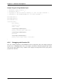
4-4. Port 7 LED2 Control ...................................................................................4-22
4-4-1. Port 7 Registers ........................................................................................... 4-22
4-4-2. Changing LED2 Color .................................................................................. 4-23
4-5. Standard I/O over Serial Link.....................................................................4-26
4-5-1. JOB60851 Board Standard I/O.................................................................... 4-26
4-5-2. Serial Port .................................................................................................... 4-27
4-5-3. read() and write() Functions......................................................................... 4-29
4-5-4. Standard I/O Examples................................................................................ 4-31
4-5-5. Debugging with Standard I/O....................................................................... 4-32
iii
1. Introduction
Chapter 1 Introduction
1-1. Checking Packing List
Thank you for purchasing the JOB60851 Starter Kit.
The JOB60851 Starter Kit drives an Oki Electric Industry ML60851 Universal Serial Bus (USB)
device controller with an Oki MSM66Q573 microcontroller to create a starting point for developing
products with built-in USB support. The kit also includes sample firmware source code and the C
compiler package for the Oki MSM66 microcontroller Series, so the developer can start writing
firmware right away.
Before starting development, however, check the kit contents against the packing list in Table 1.1.1.
If a component is missing or damaged during shipping, please contact your Oki Electric distributor
or Technocollage and include the JOB60851 serial number. Replacement is free within one (1)
month of delivery.
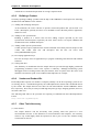
Table 1.1.1. Packing List
JOB60851
USB cable
RS-232c cable
AC adapter
CD-ROM
Two 60-pin user connectors
Introduction (this page)
1
1
1
1
1
2
1
The CD-ROM contains the following directories and files.
\Document
Documentation
\CC665S
C compiler User's Manual, etc.
\JOB60851
JOB60851 Starter Kit User's Guide, etc.
\M66573
MSM66573 User's Guide, etc.
\ML60851C
USB controller documentation, etc.
\Package
Compiler package and sample source code
\Cc665s
C compiler package, etc.
\Host
Sample files for evaluating USB operation, etc.
\Sample
Sample programs, etc.
\Usb_firm
Sample source code for MSM60851C control software: Hot plugging
(a.k.a. dynamic insertion and removal) capability for USB device, loopback test,
etc.
Before using this product, read through to the end of this section ("Introduction"). Detailed
descriptions start in Section 2 "Putting Board through Its Paces."
If a component is missing or damaged during shipping, please contact your Oki Electric distributor
with the included JOB60851 serial number. Replacement is free within one month of delivery.
Technical support for this product is limited to the product description. We do not offer personalized
support in Japanese or English, not by e-mail or fax and especially not over the telephone.
page 1-2
Chapter 1 Introduction
1-2. Host Environment
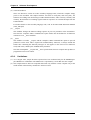
The JOB60851 Starter Kit assumes the following development environment.
• Microsoft Windows 98
• USB interface fully compatible with Microsoft Windows 98 USB driver
• Terminal emulation software
The compiler package will also run under Microsoft Windows 95 and MS-DOS version 5.0 or later,
but the JOB60851 board will not be accessible as a USB device.
page 1-3
Chapter 1 Introduction
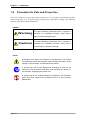
1-3. Precaution for Safe and Proper Use
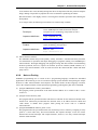
This User’s Guide uses various labels and icons that serve as your guides to operating this product
safely and properly so as to prevent death, personal injury, and property damage. The following
table lists these labels and their definitions.
Labels
This label indicates precautions that, if ignored or
Warning
otherwise not completely followed, could lead to
death or serious personal injury.
This label indicates precautions that, if ignored or
Caution
otherwise not completely followed, could lead to
personal injury or property damage.
Icons
A triangular icon draws your attention to the presence of a hazard.
The illustration inside the triangular frame indicates the nature of the
hazard—in this example, an electrical shock hazard.
A circular icon with a solid background illustrates an action to be
performed. The illustration inside this circle indicates this action—in
this example, unplugging the power cord.
A circular icon with a crossbar indicates a prohibition. The illustration
inside this circle indicates the prohibited action—in this example,
disassembly.
page 1-4
Chapter 1 Introduction
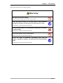
Please read this page before using the product.
Warning
Use only the specified voltage.
Using the wrong voltage risks fire and electrical shock.
At the first signs of smoke, an unusual smell, or other problems,
unplug the emulator and disconnect all external power cords.
Continued use risks fire and electrical shock.
Do not use the product in an environment exposing it to moisture
or high humidity.
Such exposure risks fire and electrical shock.
Do not pile objects on top of the product.
Such pressure risks fire and electrical shock.
At the first signs of breakdown, immediately stop using the
product, unplug the emulator, and disconnect all external power
cords.
Continued use risks fire and electrical shock.
page 1-5
Chapter 1 Introduction
Please read this page before using the product.
Caution
Do not use this product on an unstable or inclined base as it can
fall or overturn, producing injury.
Do not use this product in an environment exposing it to
excessive vibration, strong magnetic fields, or corrosive gases.
Such factors can loosen or even disconnect cable connectors, producing a
breakdown.
Do not use this product in an environment exposing it to
temperatures outside the specified range, direct sunlight, or
excessive dust.
Such factors risk fire and breakdown.
Use only the cables and other accessories provided.
Using non-compatible parts risks fire and breakdown.
Always observe the specified order for turning equipment on and
off.
Using the incorrect order risks fire and breakdown.
Do not use the cables and other accessories provided with other
systems.
Such improper usage risks fire.
Before connecting or disconnecting the cables and the
accessories, the power source for the emulator must be turned
OFF.
Connections or disconnections performed while the power source is ON risk
fire and damage to the system.
page 1-6
Chapter 1 Introduction
Notation
This manual utilizes the following notational conventions for convenience.
n Caution n
A “caution” indicates a section of the manual that
requires special attention.
n Reference n
A “reference” provides information related to the current
topic and indicates the page number of a related section
of the manual.
n Application Example n
An “application example” indicates an example related
to the current topic.
(note ×)
“(note ×)” is a reference to a numbered note that
provides supplementary information lower on the same
page.
n Note x n
“Note ×:” provides supplementary information related to
the passage marked with “(note ×).”
The descriptions below indicate keyboard keys with capitalized names inside angle brackets.
Examples
<Enter>
Enter (or Return) key
<Space>
Space key
<Ctrl>
Control key (left or right)
<Shift>
Shift key (left or right)
page 1-7
2. Putting Board through Its Paces
Chapter 2 Putting Board through its Paces
2-1. Setup
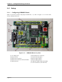
2-1-1.
Configuring JOB60851 Board
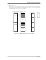
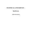
Make sure that the switches and jumpers numbered 4, 7, 8, and 9 in Figure 2.1.1 are all in their
factory default positions, B.
Figure 2.1.1. JOB60851 Board, Top View
(1) AC adapter jack
(2) Power switch
(3) Flash writer connector
(4) Flash writer selection switch (FW-SEL)
(5) USB connector
page 2-2
(6) Serial (RS-232C) connector
(7) Clock selection jumper
(8) Power supply jumpers
(9) Power supply jumpers
(10) Indicator LEDs (LED1 and LED2)
(11) User connectors (CN1 and CN2)
Chapter 2 Putting Board through its Paces
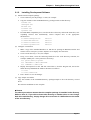
2-1-2.
Installing Development Software
(1) Install CC665S compiler package
1. Create a directory for the package--c:\665s, for example.
2. Copy the contents of the CD-ROM directory \package\cc665s to that directory.
readme.txt
c665spak.exe
mac66k.exe
rtl665s.exe
tgt665s.exe
3. In an MS-DOS compatibility box, switch to the above directory and run the .EXE files, selfexpanding archives that automatically extract compiler files to the appropriate
subdirectories.
C:\665s>c665spak.exe
C:\665s>mac66k.exe
C:\665s>rtl665s.exe
C:\665s>tgt665s.exe
(2) Configure environment
<Enter>
<Enter>
<Enter>
<Enter>
1. Make a copy of the standard Windows 9x .PIF file for opening an MS-DOS window and
rename it 665s--665s.pif if you have Explorer set to display file extensions.
2. Create a work directory--c:\test, for example.
3. Using a text editor, create the following batch file in the work directory--c665.bat, for
example. (Modify the c:\665s portions as necessary.)
set path=\665s;c:%path%
set INCL66K=c:\665s\INCLUDE
set LIB66K=c:\665s\LIB
4. Display the Properties for the .PIF file created above, click the Program tab, and set the
Work directory and Batch file fields to the names used above.
c:\test
c:\test\c665s.bat
5. Press <Enter> to save the changes.
(3) Copy sample executables
Copy the contents of the CD-ROM directory \package\sample to the work directory created
above.
The software installation is now complete.
n Note n
The above procedures assume that the compiler package is installed in the directory
\665s on drive C:. If you wish to locate this directory on another drive or even change
both drive and directory, simply change all occurrences of c:\665s above to the name
of the new directory.
Page2-3
Chapter 2 Putting Board through its Paces
2-1-3.
Connecting Board
This section gives the procedures for preparing the JOB60851 board for connection to the
development host.
1.
Make sure that the Flash writer selection switch (FW-SEL, #4 in Figure 2.1.1) is in its B
position.
2.
Plug the AC adapter into the jack (#1 in Figure 2.1.1) on the board. Make sure that the power
(#2 in Figure 2.1.1) is OFF.
3.
Plug one end of the USB cable into the connector (#5 in Figure 2.1.1) on the board. Connect the
other end into the host controller.
2-2. Running Default Program
This section gives the procedures for running the program shipped in the MSM66Q573 Flash
memory.
2-2-1.
Installing USB Driver
The included CD-ROM includes the necessary USB driver as well as host software, used in the next
Section, for testing bulk data flow.
1.
Create a directory for the host software--c:\usb, for example.
2.
Copy the contents of the CD-ROM directory \package\host to that directory.
3.
Rwbulk.exe
Bulkusb.sys
Bulkusb.inf
Connect the JOB60851 board as described in Section 2.1.3 above and apply power to it.
4.
When Windows 98 automatically detects the new device, install the driver using the Windows
98 driver wizard. (Have the Windows 98 CD-ROM or CABs handy.)
2-2-2.
Running Flash Memory Program
The JOB60851 Starter Kit ships with a program already in the MSM66Q573 Flash memory. The
executable Rwbulk.exe installed above is for transferring data to and from this program.
1.
2.
Open an MS-DOS window and change to the directory containing Rwbulk.exe--c:\usb in our
example.
C:\usb>rwbulk.exe
<Enter>
Run Rwbulk.exe to display the built-in help screen.
Usage for RwBulk:
RwBulk type [options]
type : INFO -- dump USB configuration and pipe info
BULK -- Read/Write test
DESC -- Get Descriptor test
CLASS -- Class Request test
page 2-4
Chapter 2 Putting Board through its Paces
VENDOR -- Vendor Request test
3.
Detail Usage
RwBulk
RwBulk
RwBulk
RwBulk
RwBulk
for -? option:
INFO -?
BULK -?
DESC -?
CLASS -?
VENDOR -?
Examples:
RwBulk
RwBulk
RwBulk
RwBulk
RwBulk
-u
DESC 03 00 00 00FF
-o Pipe00 -fo out.dat -vl 2
-i 1 -r 8192 -fi in.dat -vl 2
VENDOR NONE DEVICE -r 00 -v 0000 -i 0000 -l 0000
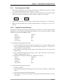
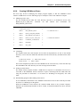
Use the -u command line option to view the USB pipe numbers.
C:\usb>rwbulk.exe BULK –? <Enter>
Usage for Read/Write test:
RwBulk [BULK] [-options]
-i [s] where s is the input pipe
-o [s] where s is the output pipe
-r [n] where n is number of bytes to read
-w [n] where n is number of bytes to write
-fi [fn] where fn is a filename for the input pipe
-fo [fn] where fn is a filename for the output pipe
-vl [n] where n is verbose level(0,2,5, default=2)
-c [n] where n is number of iterations (default=1, 0 is infinity)
The options and the meanings are:
3.
-i [s]
To specify the input pipe name the device(JOB60851) to the host direction.
-o [s]
To specify the output pipe name the host to the device(JOB60851) direction.
-r [n]
To activate operation of n-bytes read from the input pipe
-w [n]
To activate operation of n-byte write into the output pipe.
-fi [fn]
To specify a file name for bulk in operation using the input pipe.
-fo [fn]
To specify a file name for data bulkout operation using bulk out pipe.
-vl [n]
To specify verbose level as 0, 2 ro 5
-c [n]
To specify the number of iterations of specified write and read operations
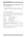
Use the -u command line option to view the USB pipe numbers.
C:\usb>rwbulk.exe –u
<Enter>
Page2-5
Chapter 2 Putting Board through its Paces
"USB_ENDPOINT_DESCRIPTOR for Pipe00"
"USB_ENDPOINT_DESCRIPTOR for Pipe01"
"USB_ENDPOINT_DESCRIPTOR for Pipe02"
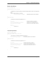
The software defines three pipes, PIPE00 to PIPE02. The first is for output--that is, from the
development host to the JOB60851 board. The other two are for input (in the opposite
direction).
PIPE00→OUTPUT:PC→From host to JOB60851
PIPE01→INPUT:JOB60851→To host from JOB60851
PIPE02→INPUT:JOB60851→To host from JOB60851
4.
Try one data transfer in each direction.
C:\USB>rwbulk.exe -o PIPE00 -w 1024 -i PIPE01 -r 1024
<Enter>
This command line writes one kilobyte of test data using output pipe PIPE00 and then reads the
same amount of data using input pipe PIPE01.
The following messages appear if both operations are successful.
Device Opened successfully.
<pipe00> W (tot:1024 @ 17:04:16) : req 1024 - 1024 written
<pipe01> R (tot:1024 @ 17:04:16) : req 1024 - 1024 read
5.
Try multiple transfers.
C:\USB>rwbulk.exe -o PIPE00 -w 1024 -i PIPE01 -r 1024 –c 10
<Enter>
This command line adds a repeat count of ten, so should produce ten such message pairs.
Opened successfully.
Device Opened successfully.
<pipe00> W (tot:1024 @ 17:21:07) : req 1024 - 1024 written
<pipe01> R (tot:1024 @ 17:21:07) : req 1024 - 1024 read
:
:
<pipe00> W (tot:9216 @ 17:21:07) : req 1024 - 1024 written
<pipe01> R (tot:9216 @ 17:21:07) : req 1024 - 1024 read
<pipe00> W (tot:10240 @ 17:21:07) : req 1024 - 1024 written
<pipe01> R (tot:10240 @ 17:21:07) : req 1024 - 1024 read
6.
Additional operation
For more detailed operation please refer to readme.txt file in host driver (Package\Host)
directory.
2-3. Running User Programs
This section gives the procedures for downloading a program over a serial link to the JOB60851
board and then running it.
page 2-6
Chapter 2 Putting Board through its Paces
2-3-1.
Connecting Serial Cable
1.
Disconnect the USB cable from the board and plug the AC adapter into the jack (#1 in Figure
2.1.1). Make sure that the power (#2 in Figure 2.1.1) is OFF.
2.
Plug one end of the serial cable into a serial port on the development host. Serial ports usually
have an icon similar to the following, a label (COM1 or COM2), or just a number.
1
2
IOIO
or
IOIO
3.
Plug the other end of the serial cable into the serial connector (#6 in Figure 2.1.1) on the board.
4.
Make sure that the Flash writer selection switch (FW-SEL, #4 in Figure 2.1.1) is in its A
position.
2-3-2.
Loading Terminal Emulator
Checking serial link operation requires HyperTerminal, Tera Term Pro, or other terminal emulator
configured to use the following communications parameters for the serial port (COM1 or COM2)
with the serial cable to the JOB60851 board.
Speed
Word size
Parity check
Stop bits
Flow control
38,400 b/s
8 bits
None
2
None
(1) Loading and configuring HyperTerminal
1. Load HyperTerminal by double-clicking the Hypertrm.exe icon. Many Windows setups
have the HyperTerminal folder on the Start menu under Programs → Accessories →
Communications → HyperTerminal.
2. In the connection name dialog box that appears, either double-click an icon or type a name
and hit <Enter>.
3. In the configuration dialog box that appears, select a direct connection to the serial port
(COM1 or COM2) and hit <Enter>.
4. In the Properties dialog box that appears, configure the serial port.
Speed
Word size
Parity check
Stop bits
Flow control
38,400 b/s
8 bits
None
2
None
(2) Loading and configuring Tera Term Pro
1. Load Tera Term Pro.
2. In the configuration dialog box that appears, select the serial port (COM1 or COM2) and hit
<Enter>.
3. Choose the Setup menu's Serial port command.
4. In the dialog box that appears, configure the serial port and click the OK button to save the
new settings.
Page2-7
Chapter 2 Putting Board through its Paces
Speed
Word size
Parity check
Stop bits
Flow control
38,400 b/s
8 bits
None
2
None
(3) Activating JOB60851 board
Once the terminal emulator is configured, turn on the power (#2 in Figure 2.1.1).
2-3-3.
Synchronizing Link
Before communicating with the JOB60851 board, check that it and the development host are using
the same data transfer speed by downloading the file !zero.dat in the work directory--c:\test in our
example.
(1) Using HyperTerminal
1. Choose the Transfer menu's Send text file command.
2. In the dialog box that appears, double-click the file !zero.dat.
3. Wait for the response OK indicating synchronization.
(2) Using Tera Term Pro
1. Choose the File menu's Send file command.
2. In the dialog box that appears, make sure that the Binary option in the lower left corner is
selected and double-click the file !zero.dat.
3. Wait for the response OK indicating synchronization.
2-3-4.
Downloading and Executing
Next repeat the above procedure with the precompiled "Hello world!" program (main.hex) in the
work directory--c:\test in our example.
(1) Using HyperTerminal
1. Choose the Transfer menu's Send text file command.
2. In the dialog box that appears, double-click the file main.hex.
3. Wait for the response "Hello World" indicating successful downloading and execution.
4. To terminate communications, close the window and answer "Yes" to the query asking
permission to break the link.
5. Answering "Yes" to the query asking whether to save the session saves the current settings
under the name first entered or selected above in Section 2.3.2 for reuse next time.
(2) Using Tera Term Pro
1. Choose the File menu's Send file command.
2. In the dialog box that appears, make sure that the Binary option in the lower left corner is
selected and double-click the file main.hex.
3. Wait for the response "Hello World" indicating successful downloading and execution.
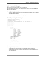
(3) Compiling, downloading, and executing a program
The above procedures simply download a precompiled program that was ready to run. Now it is
time to compile an actual user program. By way of illustration, the following simply modifies
page 2-8
Chapter 2 Putting Board through its Paces
the above program to display a different string.
1. Copy the source code main.c to a new name, test.c, in the work directory--c:\test in our
example.
2. Open the copy in a text editor.
#include <stdio.h>
#include <stdlib.h>
#include <m66573.h>
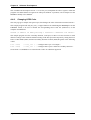
void main(void)
{
std_init_573();
S0BUF = 0x0A;/* 1st byte send to get transmit ready status */
printf_c("Hello World!! \n");
for(;;);
}
3. Modify the string in line 10, replacing "World" with your own name.
4. Save the modified version. Exit or minimize the text editor.
5. Double-click the 665s.pif icon and enter the following command line to compile the new
version into test.hex, an executable for downloading to the JOB60851 board.
n Note n
Case counts for command line options (/T, /WIN, and /H here), but not for the
command name (cl665s) or file names.
6. Repeat the appropriate download procedure above substituting the new program, test.hex,
for main.hex.
7. Wait for your name to appear.
2-4. Overwriting Flash Memory Contents
As already mentioned in Section 2.2 above, the board ships with a test program in the MSM66Q573
Flash memory. This may be overwritten, however, with a PW66K Flash programmer.
For further details about flash programmer, contact Oki Electric Device Sales or distributor.
Page2-9
3. System Specifications
Chapter 3 System Specifications
3-1. System Components
3-1-1.
System Objective
The JOB60851 board's primary objective is lowering the threshold for developing new USB devices.
3-1-2.
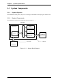
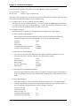
System Components
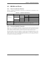
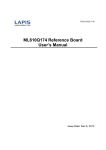
The JOB60851 board has the components shown in Figure 3.1.1.
JOB60851
MSM66Q573
ROM
(LOADER)
ExRAM
Flash
ML60851C
Serial link
PC
TERMINAL
Figure 3.1.1. System Block Diagram
page 3-2
PC
USB HOST
Windows98
USB link
Chapter 3 System Specifications
3-2. Hardware Specification
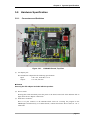
3-2-1.
Connectors and Switches
Figure 3.2.1. JOB60851 Board, Top View
(1) AC adapter jack
The included AC adapter has the following specifications.
Input:
Output:
100 V AC, 50/60 Hz, 18 VA
10 V DC, 850 mA
n Note n
Use only the AC adapter included with the product.
(2) Power switch
Pressing this switch alternately turns the power to the board on and off. If the indicator fails to
light, check the AC adapter connections.
(3) Flash writer connector
This set of pins connects to the PW66K Flash writer for rewriting the program in the
MSM66Q573 Flash memory. For further details, contact Oki Electric Device Sales at +81-35445-6027.
page 3-3
Chapter 3 System Specifications
(4) Flash writer selection switch (FW-SEL)
The B side of this switch is for executing the program in the MSM66Q573 Flash memory or
overwriting it with the PW66K Flash writer (available separately).
(5) USB connector
This Series B connector is for the USB cable.
(6) Serial (RS-232C) connector This 9-pin female DSUB connector is for the RS-232C cable
linking the JOB60851 board to a terminal emulator running on the host personal computer.
n Note n
Always include the JOB60851 serial number with any queries. It is printed in black ink
on the underside of the board, near the serial connector.
(7) Clock selection jumper
This jumper offers a choice of two onboard MSM66Q573 microcontroller system clock
frequencies: 16 (A) and 24 (B) MHz.
(8), (9) Power supply jumpers
These jumpers offer a choice of two power supplies: USB (A) and AC adapter (B). Both must
be in the same position.
(10) Indicator LEDs (LED1 and LED2)
LED1 monitors the LOAD_SEL signal
LED2 is connected to Port 7, so is under program control. The built-in loader, for example,
changes it from the default red that it has when the power is first applied to green when a
downloaded program is executing.
(11) User connectors (CN1 and CN2)
These connectors provide access to almost all onboard MSM66Q573 microcontroller pins as
well as to the ML60851C USB controller pins. The JOB60851 Starter Kit even includes the
matching connectors for easily connecting these to the user application circuit under
development.
page 3-4
Chapter 3 System Specifications
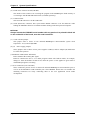
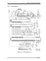
3-2-2.
Circuit Diagram
Figure 3.2.2. Circuit Diagram (1/2)
page 3-5
Chapter 3 System Specifications
Figure 3.2.3. Circuit Diagram (2/2)
n Note n
An electronic version of this circuit diagram is available in the CD-ROM directory
\document\job60851 as the MS Power Point document cir_j851.ppt.
page 3-6
Chapter 3 System Specifications
3-2-3.
Parts List
Tables 3.2.1 and 3.2.2 list the parts on the JOB60851 board.
Table 3.2.1. Parts List (1/2)
Item
1
Quantity
15
2
3
4
5
6
7
8
9
10
1
1
3
2
1
1
4
1
15
11
12
13
14
15
16
17
18
19
20
21
22
23
24
25
26
27
28
29
30
31
32
33
34
35
36
37
38
1
2
3
3
2
6
1
2
1
5
3
1
2
1
1
1
1
1
1
2
1
2
1
1
1
1
1
1
Reference
C13,C15,C16,C17,C18,C19,C20,
C21,C22,C23
C24,C25,C26,C27,C28
C7
C6
C4,C5,C8
C2,C3
C31
C9
C1,C10,C11,C12
C14
R1,R2,R3,R4,R7,R8,R12,R17,R18,R19
R30,R31,R32,R33,R34
R5
R6,R36
R9,R22,R23
R10,R11,R15
R13,R14
R16,R20,R21,R24,R26,R27
R25
R28,R29
R35
RA1,RA2,RA3,RA4,RA5
D1,D2,D3
DB1
FB1,FB2
L1
IC1
IC2
IC3
IC4
IC5
IC6,IC11
IC7
IC8,IC12
IC9
IC10
IC13
IC14
IC15
IC16
39
40
41
2
1
2
LED1,LED2
USB
CN1,CN2
42
43
1
1
FW-CN
UART-CN
44
45
46
47
1
1
1
1
FW-SEL
P-SW
RST
PWR
48
49
50
1
1
1
XT1
XT2
XT3
51
1
XT4
52
1
PCB
Part
0.1uF
DSCRIPTION
Ceramic Capacitor
1000pF
330pF
5pF
15pF
0.47uF
10uF
4.7uF
0.1uF
100K
Ceramic Capacitor
Ceramic Capacitor
Ceramic Capacitor
Ceramic Capacitor
Tantalum Capacitor
16v Tantalum Capacitor
25v Tantalum Capacitor
35v Tantalum Capacitor
Chip Resistor
100
51K
220
1M
1.5K
10K
12K
470K
1K
100K x8
DIODE
DIODE
FB
2.2uH
M66Q573
HM628128AL
M27C256H
M60851A
74HC58
74HC00
74HC04
74HC08
74HC32
74HC27
TC7S66FU
MAX203CWP
NJM7805F
XC62FP3302
Chip Resistor
Chip Resistor
Chip Resistor
Chip Resistor
Chip Resistor
Chip Resistor
Chip Resistor
Chip Resistor
Chip Resistor
Chip Network Resistor
80v,100mA
200v,1A Bridge Type
Ferrite Bead Inductor
2.2uH Inductor
Micro Controller
128K x 8b SRAM
32K x 8 EPROM
USB Device Interface
Logic Gate
Logic Gate
Logic Gate
Logic Gate
Logic Gate
Logic Gate
1ch Analog Switch
RS232 Xlator
3-term 5v(1A) Regulator
3-term 3.3v(0.5A)
Regulator
LED (bright red/green)
USB 'B' type Receptacle
60pin Header Connector
GL3ED8
USB-212-T
HIF3HB-60DA2.54DSA
5267-06A-X
6pin Servo Connector
17LE-13090- 9pin RS232C Conn. Female
27(D3AB)
MIS-AC-3--2N
Slide Switch
UB-26SKP1R
Power Switch
SMT1-01
Reset Switch
HEC0470-01Power Input Connector
630
MXO-51C 24MHz 24MHz Crystal Oscillator
HC49/U-S 16MHz 48MHz Quartz Crystal
DT-38
32.768KHz Quartz Crystal
32.768KHz
HC49/U-S
48MHz +/-100ppm
48MHz100ppm
Quartz Crystal
QTU-11399
Printed Circuit Board
page 3-7
Chapter 3 System Specifications
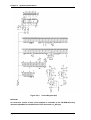
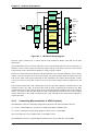
3-2-4.
Memory Maps
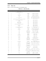
This Section gives code and data memory maps for the various JOB60851 operation modes.
(1) Download mode
This mode maps the code memory to the EPROM and the data memory to program RAM and
Flash memory. It uses the loader, a program stored in the EPROM, to download a user
application program over a serial link from the development host to program RAM.
Loader Mode 1 memory map ( Load_Sel/ = L ) ( EA/ = L )
Data Memory
Program Memory
0:0000 h
0:0200 h
0:0000 h
Ext._EPROM(E)
0:1200 h
SFR/XSFR
Ext._EPROM
Ext._SRAM
0:0000 h
0:0000 h
Int._RAM
Ext._SRAM(A)or(B)
(A)
(E)
0:2000 h
(Loader Program)
0:3000 h
ML60851A
Ext._SRAM(A)or(B)
0:7 FFFh
0:8000 h
0:8000 h
(B)
Ext._SRAM(A)or(B)
1:0000 h
1:0200 h
1:1200 h
SFR/XSFR
0:7 FFFh
1:0000 h
Int._RAM
Ext._SRAM(C)or(D)
(C)
1:2000 h
ML60851A
1:3000 h
Ext._SRAM(C)or(D)
1:8000 h
1:8000 h
Ext._SRAM(C)or(D)
1:FFFFh
(D)
1:FFFFh
Figure 3.2.4. Memory Map for Download Mode
page 3-8
Chapter 3 System Specifications
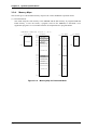
(2) Flash execution mode
This mode maps the code memory to the Flash memory and the data memory to work RAM. It
executes the program in Flash memory. Cutting the power does not erase the program, which
starts automatically when the power is next applied.
Loader Mode2 memory map ( Load_Sel/ = L ) ( EA/ = H )
Data Memory
Program Memory
0:0000h
0:0000h
0:0200h
Int._FlashROM
0:1200h
SFR/XSFR
Ext._EPROM
Ext._SRAM
0:0000h
0:0000h
Int._RAM
Ext._SRAM(A)or(B)
(A)
(E)
0:2000h
(Loader Program)
ML60851A
0:3000h
Ext._SRAM(A)or(B)
0:8000h
0:8000h
(B)
Ext._SRAM(A)or(B)
1:0000h
1:0000h
1:0200h
1:1200h
Int._FlashROM
(Only M66Q577)
SFR/XSFR
0:7FFFh
1:0000h
Int._RAM
Ext._SRAM(C)or(D)
(C)
1:2000h
ML60851A
1:3000h
Ext._SRAM(C)or(D)
1:8000h
1:8000h
Ext._SRAM(C)or(D)
1:FFFFh
1:FFFFh
(D)
1:FFFFh
Figure 3.2.5. Memory Map for Flash Execution Mode
page 3-9
Chapter 3 System Specifications
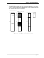
(3) Application mode
This mode maps the code memory to program RAM and the data memory to work RAM. It
executes the program in program RAM.
AP Mode 1 memory map ( Load_Sel/ = H ) ( EA/ = L )
Data Memory
Program Memory
0:0000 h
0:0200 h
0:0000 h
Ext._SRAM(A)
(AP Program)
0:1200 h
SFR/XSFR
Ext._EPROM
Ext._SRAM
0:0000 h
0:0000 h
Int._RAM
Ext._SRAM(C)
(A)
(E)
0:2000 h
0:3000 h
ML60851
Ext._SRAM(C)
0:8000 h
0:7 FFFh
0:8000 h
0:7 FFFh
Ext._SRAM(B)
(AP Program)
1:0000 h
1:0000 h
1:0200 h
Ext._SRAM(A)
(AP Program)
(B)
Ext._SRAM(D)
1:1200 h
SFR/XSFR
1:0000 h
Int._RAM
Ext._SRAM(C)
(C)
1:2000 h
ML60851
1:3000 h
Ext._SRAM(C)
1:8000 h
1:8000 h
1:8000 h
Ext._SRAM(B)
Ext._SRAM(D)
(AP Program)
1:FFFFh
1:FFFFh
(D)
1:FFFFh
Figure 3.2.6. Memory Map for Application Mode
page 3-10
Chapter 3 System Specifications
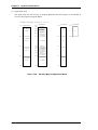
(4) Flash rewrite mode
This mode maps the code memory to the Flash memory and the data memory to work RAM. It
executes the program in Flash memory. Cutting the power does not erase the program, which
starts automatically when the power is next applied.
AP Mode2 memory map ( Load_Sel/ = H ) ( EA/ = H )
Data Memory
Program Memory
0:0000h
0:0000h
0:0200h
Int._FlashROM
0:1200h
SFR/XSFR
Ext._EPROM
Ext._SRAM
0:0000h
0:0000h
Int._RAM
Ext._SRAM(C)
(A)
(E)
0:2000h
(AP Program)
ML60851A
0:3000h
Ext._SRAM(C)
0:8000h
(B)
Ext._SRAM(D)
1:0000h
1:0000h
1:0200h
1:1200h
Int._FlashROM
(Only M66Q577)
0:7FFFh
0:8000h
SFR/XSFR
1:0000h
Int._RAM
Ext._SRAM(C)
(C)
1:2000h
ML60851A
1:3000h
Ext._SRAM(C)
1:8000h
1:8000h
Ext._SRAM(D)
1:FFFFh
1:FFFFh
(D)
1:FFFFh
Figure 3.2.7. Memory Map for Flash Rewrite Mode
page 3-11
Chapter 3 System Specifications
3-3. System Limitations
3-3-1.
Resources Uses
The user connectors (CN1 and CN2) on the JOB60851 board make available to the user application
system almost all onboard MSM66Q573 microcontroller pins and thus most microcontroller
functionality.
The JOB60851 board, however, monopolizes certain microcontroller resources in running its own
system, making them unavailable to the developer.
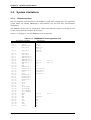
Tables 3.3.1 through 3.3.3 list the MSM66Q573 pin assignments.
Table 3.3.1. MSM66Q573 Pin Assignments (1/2)
IC1.1
IC1.2
IC1.3
IC1.4
Pin Number and Name
P10-4
P10-5
TM5EVT/P10-7
RXD1/P8-0
IC1.5
TXD1/P8-1
IC1.6
IC1.7
IC1.8
IC1.9
IC1.10
IC1.11
IC1.12
IC1.13
IC1.14
IC1.15
IC1.16
IC1.17
IC1.18
IC1.19
IC1.20
IC1.21
IC1.22
IC1.23
IC1.24
IC1.25
IC1.26
IC1.27
IC1.28
IC1.29
IC1.30
IC1.31
IC1.32
IC1.33
IC1.34
IC1.35
IC1.36
IC1.37
IC1.38
IC1.39
IC1.40
RXC1/P8-2
TXC1/P8-3
TM4OUT/P8-4
PWM2OUT/P8-6
PWM3OUT/P8-7
PWM0OUT/P7-6
PWM1OUT/P7-7
VDD
GND
HLDACK/P9-7
EXINT4-P9-0
EXINT5/P9-1
P9-2
P9-3
EXINT0/P6-0
EXINT1/P6-1
EXINT2/P6-2
EXINT3/P6-3
P6-4
P6-5
P6-6
P6-7
P5-4/CPCM0
P5-5/CPCM1
P5-6/TM0OUT
P5-7/TM0EVT
RESb
NM1
EAb
VDD
XT0
XT1b
GND
OSC0
OSC1b
page 3-12
Connections
IC12.2(R12)
IC5.4
R8,R35
MAX203.20
(J13.3)
MAX203.2
(J14.3)
IC11.9
IC11.12
Vcc
Vcc
IC11.10
IC11.13
IC4.12(R16)
IC12.4(R17)
FW-SEL.1,2
FW-SEL.3,5
IC12.8
R7
FW-SEL.8
Vcc
XT3
XT3
Vcc
J1
XT2
IC12.12
Chapter 3 System Specifications
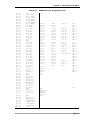
Table 3.3.1. MSM66Q573 Pin Assignments (2/2)
IC1.41
IC1.42
IC1.43
IC1.44
IC1.45
IC1.46
IC1.47
IC1.48
IC1.49
IC1.50
IC1.51
IC1.52
IC1.53
IC1.54
IC1.55
IC1.56
IC1.57
IC1.58
IC1.59
IC1.60
IC1.61
IC1.62
IC1.63
IC1.64
IC1.65
IC1.66
IC1.67
IC1.68
IC1.69
IC1.70
IC1.71
IC1.72
IC1.73
IC1.74
IC1.75
IC1.76
IC1.77
IC1.78
IC1.79
IC1.80
IC1.81
IC1.82
IC1.83
IC1.84
IC1.85
IC1.86
IC1.87
IC1.88
IC1.89
IC1.90
IC1.91
VDD
P11-0/WAIT
P11-1/HOLD
P11-2/CLKOUT
P11-3/XTOUT
P11-6/TM9OUT
P11-7/TM9EVT
P3-1/PSENb
P3-2/RDb
P3-3/WRb
P0-0/D0
P0-1/D1
P0-2/D2
P0-3/D3
P0-4/D4
P0-5/D5
P0-6/D6
P0-7/D7
GND
P4-0/A0
P4-1/A1
P4-2/A2
P4-3/A3
P4-4/A4
P4-5/A5
P4-6/A6
P4-7/A7
P1-0/A8
P1-1/A9
P1-2/A10
P1-3/A11
P1-4/A12
P1-5/A13
P1-6/A14
P1-7/A15
A16/P2-0
A17/P2-1
A18/P2-2
A19/P2-3
VDD
VREF
A10/P12-0
A11/P12-1
A12/P12-2
A13/P12-3
A14/P12-4
A15/P12-5
A16/P12-6
A17/P12-7
AGND
RXD0/P7-0
IC1.92
TXD0/P7-1
IC1.93
IC1.94
IC1.95
IC1.96
IC1.97
IC1.98
IC1.99
IC1.100
GND
RXC0/P7-2
TM3OUT/P7-4
TM3EVT/P7-5
SIOCK3/P10-0
SIOI3/P10-1
SIOO3/P10-2
P10-3
Vcc
IC3.22
IC6.12
IC6.13
IC2.13
IC2.14
IC2.15
IC2.17
IC2.18
IC2.19
IC2.20
IC2.21
Vcc
IC2.12
IC2.11
IC2.10
IC2.9
IC2.8
IC2.7
IC2.6
IC2.5
IC2.27
IC2.26
IC2.23
IC2.25
IC2.4
IC2.28
IC2.3
IC5.9
IC10.1
IC10.13
IC10.2
Vcc
Vcc
IC8.5
IC8.9
IC7.13
IC3.11
IC3.12
IC3.13
IC3.15
IC3.16
IC3.17
IC3.18
IC3.19
IC9.10
IC3.10
IC3.9
IC3.8
IC3.7
IC3.6
IC3.5
IC3.4
IC3.3
IC3.25
IC3.24
IC3.21
IC3.23
IC3.2
IC3.26
IC3.27
IC3.1
IC4.32
IC4.31
IC4.30
IC4.29
IC4.28
IC4.27
IC4.26
IC4.25.(J4.2)
IC4.44
IC4.43
IC4.42
IC4.41
IC4.38
IC4.37
IC4.36
IC4.35
IC10.3
IC8.2
IC10.4
IC52
R34
R26
R27
RA1.9
RA1.2
RA1.8
RA1.3
RA1.7
RA1.4
RA1.6
RA1.5
R33
RA2.5
RA2.6
RA2.4
RA2.7
RA2.3
RA2.8
RA2.2
RA2.9
RA3.5
RA3.6
RA3.4
RA3.7
R31
R32
R25
RA3.3
RA3.8
RA3.2
RA3.9
R10
GND
MAX203.20
(J13.2)
MAX203.2
(J14.2)
Vcc
page 3-13
4. Software Development
Chapter 4 Software Development
Section 4-1. "USB Basics" provides an overview of the Universal Serial Bus (USB) specifications as
well as URLs for obtaining detailed specifications.
Section 4-2. "Sample USB Firmware" provides a functional overview of the sample device firmware
shipped with the JOB60851 Starter Kit and procedures for modifying the source code and evaluating
the result.
Section 4-3. "USB Bits and Pieces" covers device controller specifications, device controller
operational overview, notes to device developers. etc.
Sections 4-4. "Port 7 LED2 Control" and 4.5 "Standard I/O over Serial Link" give procedures for
modifying the sample source code for simple debugging with the JOB60851 board. They cover both
procedures controlling the onboard LED2 and those using standard I/O library functions (printf(),
scanf(), etc.) over the serial link to a terminal emulator.
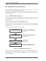
4-1. USB Basics
4-1-1.
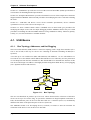
Bus Topology, Addresses, and Hot Plugging
The Universal Serial Bus (USB) features a tiered star topology with a single host controller (a.k.a.
root or Tier 0 hub) at the top of a device tree consisting of functions branching off hubs(a.k.a.
repeaters).
A tree has up to 127 such devices (hubs and functions) with addresses 1 to 127. The address 0 is
reserved for use as the default control address that USB devices use when they are first powered on
or reset. Requests from the host controller use this default address to determine the structure of this
new device and assign it an address. This highly flexible arrangement holds the key to hot plugging
(a.k.a. dynamic insertion and removal).
HOST
HOST
CONTROLLER
CONTROLLER
ROOT
ROOTHUB
HUB
HUB
HUB
DEVICE
DEVICE
DEVICE
DEVICE
HUB
HUB
DEVICE
DEVICE
DEVICE
DEVICE
HUB
HUB
DEVICE
DEVICE
Figure 4.1.1. Bus Topology
The tree can chain hubs to produce up to five tiers. Cables between hubs or between a hub and a
device can be up to five meters long. To prevent the formation of illegal loopback connections at
hubs, the downstream ports on the root and other hubs use a connector (Series A) mechanically
different from those on the upstream ports on devices (Series B).
The JOB60851 board is for developing devices, not hubs, so features a Series B connector for
connection to the Series A one on the root or other hub.
page 4-2
Chapter 4 Software Development
4-1-2.
Specification Documents
USB specifications have been established by the USB Implementers Forum. These and other
materials are available on the World Wide Web at the following URLs.
Forum top page
Developers section
Developer documentation
Device classes
Compliance testing
http://www.usb.org/developers/
http://www.usb.org/developers/
http://www.usb.org/developers/docs.html
http://www.usb.org/developers/devclass.html
http://www.usb.org/developers/complian.html
The USB Implementers Forum augments the core specifications, the document specifying
characteristics shared by all USB devices, with separate Universal Serial Bus Device Class
Specifications for specific device types.
4-1-3.
Core Specifications
This document covers common characteristics of host controllers, hubs, devices, and transmission
pathways. Specific areas include an overview of USB communications, functionality, and bus
drivers; physical and electrical specifications for connectors, transmission pathways, and other
components; and the standard command-response device requests that all USB devices must support.
The current version number is 1.1.1
n Note n
Note: Version 1.1 superseded version 1.0 in October 1998. The older version is still
available on the World Wide Web. Apart from such additions as InterruptOut transfers,
most changes involve removing ambiguities in the older version. The electrical
specifications in Chapter 7 now provide more detail. The protocol layer specifications
in Chapter 8 add descriptions of STALL operation for the default control pipe and of
the Data stage of control transfers. The device framework specifications in Chapter 9
add descriptions of state processing for request errors. The hub specifications in
Chapter 11 have been completely rewritten.
Chapter 1
Chapter 2
1
Chapter 3
Chapter 4
Chapter 8
Introduction
Terms and
Abbreviations
Background
Architectural Overview
Protocol Layer
Chapter 9
UBS Device Framework
Objectives and target audience for USB specifications
Definitions of key terms used
Design goals and requirements addressed
Overview of USB architecture and key concepts
Packet definitions and detailed descriptions of
transaction formats for error detection and recovery,
etc.
Detailed descriptions of device states, device requests,
Version 1.1 superseded version 1.0 in October 1998. The older version is still available on the World
Wide Web. Apart from such additions as InterruptOut transfers, most changes involve removing
ambiguities in the older version. The electrical specifications in Chapter 7 now provide more detail.
The protocol layer specifications in Chapter 8 add descriptions of STALL operation for the default
control pipe and of the Data stage of control transfers. The device framework specifications in
Chapter 9 add descriptions of state processing for request errors. The hub specifications in Chapter
11 have been completely rewritten.
page 4-3
Chapter 4 Software Development
Chapter 10
Chapter 11
USB Host: Hardware
and Software
Hub Specification
standard device requests, and standard device
descriptors
Functions and operation of host hardware and
software
Hub port operation, requests, and descriptors
Chapter 4 provides a firm grounding in the USB core specifications. All developers of USB
equipment must study Chapter 5 very carefully. Hardware developers must read Chapter 7; firmware
developers, Chapters 8 and 9. Firmware developers must pay particular attention to the timing
specifications in Chapter 7.
What follows are key points from the core specifications. For complete details, refer to the
specifications available from the USB Implementers Forum web site.
4-1-4.
Data Flow Types
The USB specifications define four data flow types with the following characteristics. Flexibly
combining these four data flow types provides solutions to the communications needs of a wide
variety of applications.
Table 4.1.2. USB Data Flow Types
Control
Bulk
Interrupt
Isochronous
4-1-5.
Communication of commands and responses for device configuration and pipe
control
Transfer of relatively large, bursty data volumes with wide dynamic latitude in
transmission constraints
Transfer of small data volumes within time limits based on human-perceptible echo
or feedback response characteristics
Transfer using prenegotiated USB bandwidth with a prenegotiated delivery latency-audio data, for example--with no procedure for retransmitting data
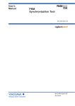
Bus Transactions
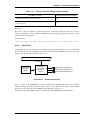
Data transfers consist of bus transactions, exchanges of basic packets between the host and a specific
device. The example below shows two such transactions.
The first data request (IN) from the host arrives when the device has no data for delivery, so the
latter returns a NAK handshake, completing the transaction. The NAK indicates two things: that the
device has no data ready and that the host should resend the request later.
The second data request (IN), in contrast, causes the device to deliver the data (DATA0) that it has
ready. The host acknowledges successful receipt of this data with an ACK, completing the
transaction.
Transactions require cirtain bit time order response, so are implemented in hardware.
Host
Device
(1) Data request (IN)
→
(3) Data request (IN)
→
(5) Successful receipt acknowledgment (ACK)
→
page 4-4
←
(2) No data (NAK)
←
(4) Data transfer (DATA0)
Chapter 4 Software Development
Figure 4.1.2. Two USB Transactions
All bus transactions begin with a token packet from the host. Devices never initiate data transfers on
their own.
The host controller is in charge of scheduling all traffic on the bus. It schedules the appropriate
transactions for the four data flow types at 1-ms intervals, which the USB documentation calls
frames.
Token packet types include data request (IN), data transfer notification (OUT), and command
transfer notification (SETUP).
4-1-6.
Packets
A packet is a continuous bit stream starting with the synchronization pattern and flowing in one
direction.
Table 4.1.3. lists the USB packet types.
PID Type
PID Name
Transmitter
Description
Token
OUT
Host
Data transfer notification
IN
Host
Data request
SOF
Host
Start of frame
SETUP
Host
Data transfer notification for control pipe
DATA0
Host/Device
Data packet PID even
DATA1
Host/Device
Data packet PID odd
ACK
Host/Device
Receiver accepts error-free packet
NAK
Device
Transmitter cannot send data
STALL
Device
Data
Handshake
Receiver cannot accept data
Control pipe request not supported
Endpoint halted
Special
4-1-7.
PRE
Host
Preamble enabling downstream bus traffic to low-speed devices
Endpoints
The USB provides separate logical communication flows, called pipes, between the host and a USB
function. The function end of a pipe is called the endpoint. This endpoint must provide buffer space
(FIFO) capable of holding at least one data packet (a.k.a. the maximum payload size).
Endpoints and pipes are characterized, at creation, by the direction (from or to host) and by the data
flow type (control, bulk, interrupt, or isochronous). There are provisions for up to 16 pipes in each
direction, for a total of 32 endpoints per function. The token packet that the host transmits to initiate
a transaction specifies the endpoint buffer with the endpoint address made up of the device address
and the endpoint number.
USB device controller capacity is expressed by the number of endpoints it has and such endpoint
specifications as supported data flow types and endpoint buffer sizes. Examining these endpoint
specifications thus reveals whether the USB device controller is suitable for the intended application.
page 4-5
Chapter 4 Software Development
4-1-8.
Data Rates
The USB supports two data rates: 12 Mb/s and 1.5 Mb/s. Table 4.1.4 lists the maximum payload
sizes for each combination of data flow type and data rate.
Table 4.1.4. Maximum Payload Sizes
Transfer Types
Control
Isochronous
Interrupt
Bulk
MAX Payload Size
12 Mbps
1.5 Mbps
8/16/32/64
8
1023 or less
N/A
64 or less
8 or less
8/16/32/64
N/A
A hub determines the data rates supported by an attached function by examining the latter's Non
Return to Zero Invert (NRZI) data signal lines (D+ and D-). A device supporting the high speed
pulls up the D+ line to the 3.3-volt power supply voltage with a 1.5-kΩ resistor; one supporting the
low speed does the same with the D- line.
The ML60851C USB controller operates exclusively at 12 Mb/s, so the JOB60851 board includes
only the D+ pull-up resistor.
4-1-9.
Device Class Specifications
The Universal Serial Bus Device Class Specifications complement the core specifications by further
standardizing USB devices for major interfaces and specific applications devices using those
interfaces.
Some interface specifications standardize the communications pathways that the USB hardware
provides for a specific purpose--the exchange of isochronous audio or image data, for example.
Others standardize USB specifications for devices combining multiple interfaces.
Table 4.1.5 lists some of the USB Device Class Specifications currently available. For further details,
refer to the following URL.
Table 4.1.5. USB Device Class Specifications
Device Class
Applicable Equipment
Human interface devices (HIDs)
Mice, keyboards, joysticks, etc.
Printers
Printers
Audio devices
Speakers, microphones, etc.
Communications devices
Modems, ISDN terminal adapters, etc.
Mass storage devices
Fl oppy disk drives, SCSI equipment, ATAPI equipment, etc.
Image devices
Digital cameras, scanners, low-rate video, etc.
There is also a standard for downloading programs to devices.
http://www.usb.org/developers/devclass.html
page 4-6
Chapter 4 Software Development
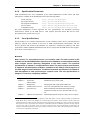
4-1-10. Device Requests
Device requests represent commands from the host to USB functions using control transfers. The
USB function parses the request, performs the necessary action, and returns the appropriate
response.
There are three types of device requests.
Table 4.1.6. Device Request Types
Standard
Requests that all USB devices must support because they hold the key to hot plugging
(a.k.a. dynamic insertion and removal)
Class-specific
Requests required by the USB Device Class Specifications for the general application
Vendor-specific
Requests implemented by the vendor for accessing functionality particular to the USB
device
A control transfer starts with a SETUP token packet followed by an 8-byte data packet containing
the following fields. Note that the meaning of the wValue and wIndex fields depends on the request
type.
Table 4.1.7. Control Transfer Data Packet
bmRequestType
bRequest
wValue
wIndex
wLength
1byte
1byte
2byte
2byte
2byte
Transfer direction, request type, and endpoint address
Request number
Value (meaning depends on the request type)
Index or offset (which depends on the request type)
Number of bytes transferred during the Data stage
A control transfer consists of up to three stages.
1.
Setup stage: The data packet following the SETUP token packet is an 8-byte command from the
host to the device. The device parses the command and, as necessary, prepares to send or
receive data.
2.
Data stage: The pipe transfers the specified data in the direction specified by the command.
Note that commands that do not involve data transfer skip this stage.
3.
Status stage: The host initiates a transaction, in the direction opposite the immediately
preceding data transfer, for reporting command success or failure from the device to the host.
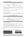
4-1-11. Standard Device Requests
The standard device requests are common ones to all USB devices. Most important are those that
support hot plugging (a.k.a. dynamic insertion and removal). Detailed descriptions are in Section 9.4 of the USB version 1.1 specifications.
Table 4.1.8. Standard Device Requests
No.
Request Name
Description
0
GET_STATUS
Return status for specified recipient
1
CLEAR_FEA TURE
Clear or disable a specific feature
3
SET_FEATURE
Set or enable a specific feature
5
SET_ADDRESS
Set device address for al future device accesses
6
GET_DESCRIPTOR
Return the specified descriptor, if it exists
page 4-7
Chapter 4 Software Development
7
SET_DESCRIPTOR
Update or add a descriptor
8
GET_CONFIGURATION
Return the current device configuration value
9
SET_CONFIGURATION
Set the device configuration value
10
GET_INTERFACE
Return the selected alternate setting for the specified interface
11
SET_INTERFACE
Set the alternate setting for the specified interface
12
SYNCH_FRAME
Set and report an endpoint's synchronization frame
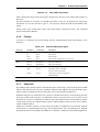
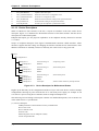
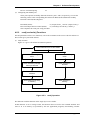
4-1-12. Device Descriptors
When a USB device first connects to the bus, it reports its attributes to the host with a device
descriptor. Figure 4.1.3 illustrates the hierarchical structure of this data structure with the device
descriptor for a bidirectional printer.
Endpoint descriptors give the physical capabilities of the endpoints already discussed in Section
4.1.7 above.
Groups of endpoint descriptors form logical communications functions called interfaces. These
interfaces support alternate settings for changing the interface and thus device characteristics. Note
that these interfaces are mutually exclusive in that only one can be in use at any given time.
n Device
o Configuration #1
u Interface #1
¡ Endpoint #1
alternate setting #0
BulkOut
; output-only printer
u Interface #1
¡ Endpoint #1
¡ Endpoint #2
alternate setting #1
BulkOut
BulkIn
; bidirectional printer
u Interface #1
¡ Endpoint #1
¡ Endpoint #2
¡ Endpoint #3
alternate setting #2
BulkOut
BulkIn
InterruptIn
; bidirectional printer
; Inform of data volumes by interrupt transfer
Figure 4.1.3. Device Descriptor for Bidirectional Printer
Higher up the hierarchy are the configuration and device layers. The same device can have multiple
configurations--drawing its power from the bus or its own local power supply, for example. It can
even start as a power-saving device and later switch to a high-consumption one.
The following are brief listings of descriptor contents. For detailed descriptions, refer to Section 9.4
of the USB version 1.1 specifications.
(1) Device descriptor
USB Specification release number in binary coded decimal
Device class code
Device subclass code
Protocol code
Maximum packet size for endpoint 0 (EP0)
Vendor and product IDs
page 4-8
Chapter 4 Software Development
Device release number in binary coded decimal
Index numbers for string descriptors describing manufacturer, product, and device serial
number
Number of possible configurations
(2) Configuration descriptor
Total size of this descriptor in bytes
Number of interfaces supported by this configuration
Unique number for this configuration
Index number for string descriptor describing this configuration
Configuration power supply attributes
Remote wake-up support
Maximum power consumption when using bus power supply
(3) Interface descriptor
Total size of this descriptor in bytes
Number of interface
Number of endpoints used by this interface
Class code
Subclass code
Protocol code
Index number for string descriptor describing this interface
(4) Endpoint descriptor Total size of this descriptor in bytes
Data flow direction (IN or OUT)
Data flow type (control, bulk, interrupt, or isochronous)
Maximum packet size (payload) for this endpoint
Interval for polling this endpoint for interrupt transfers
(5) String descriptor
Total size of this descriptor in bytes
Unicode encoded string
page 4-9
Chapter 4 Software Development
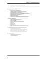
4-2. Sample USB Firmware
The JOB60851 Starter Kit includes the complete source code for use as the starting point for the user
USB firmware. To see the effects of user modifications on behavior, edit the source code, compile it,
link it into an executable .HEX file, and then download and execute this file with the procedure in
Section 2.3 "Running User Programs."
This Section outlines the entire cycle.
4-2-1.
Setup
Copy the file M851xxxx.exe from the \Usb_firm directory on the CD-ROM to a work directory-c:\work in our example. This file is a self-expanding archive that automatically extracts the sample
source code to the appropriate subdirectories shown in Table 4.2.1.
After executing this file in the work directory, open Readme.txt. This text file lists the contents of
the archive. Be sure to read the disclaimer section about rights to the source code.
Table 4.2.1. Sample USB Firmware
\Work
\Include
\Src
\66573
\Arm
\Err
\Lst
\Debug
\Release
\traffic
4-2-2.
Compiler work directory
Include files
Source files (shared files)
cc665s source code for 16-bit MSM66573 microcontrollers
ARM-SDT source code for 32-bit ARM microcontrollers
cc665s assembler error output directory
cc665s assembler listing file output directory
ARM-SDT debugging code output directory
ARM-SDT release code output directory
Sample data for use with the Computer Access Technology
Corporation (CATC) USB evaluation system.
Sample Firmware Specifications
The source code on the CD-ROM produces the sample USB firmware shipped in the MSM66Q573
Flash memory. This firmware is perfectly general code that provides the standard device request
support and standard descriptors required by the USB core specifications. It does not assume any
particular application. It supports the three data flow types (control, bulk, and interrupt) offered by
ML60851 USB controllers.
For the detailed specifications of this sample USB firmware, refer to the text file M852.txt
accompanying it in the work directory. Note that the source code supports both ML60851 and
ML60852 USB controllers and that M852.txt covers the 32-bit ARM microcontroller as well as
these two devices. Read only the sections applicable to the ML60851C USB controller and the 16bit MSM66Q573 microcontroller.
n Note n
As of August 1999, operation has been confirmed only for the MSM66Q573 plus
ML60851C combination. The ARM code is a preliminary version that does not
compile.
page 4-10
Chapter 4 Software Development
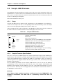
4-2-3.
Sample USB Host Software
The CD-ROM directory \package\host contains the following USB host software for testing such
things as bulk data flow. A brief overview of operation appears in Section 2.
Readme.txt
Rwbulk.exe
Bulkusb.sys
Bulkusb.inf
Software description, usage notes, etc.
Test application
WDM-USB driver
WDM-USB driver installer information file
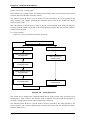
This USB host software adopts the following layered approach. For a detailed description, refer to
the accompanying text file Readme.txt.
RWbulk.exe
BulkUsb.sys
USB Host Stack
Windows user mode console application
Win32API
Windows kernel mode driver
USB Driver Interface(USBDI)
Windows WDM USB Host Protocol Stack (Microsoft)
HostController
USB
n Note n
This sample host software runs only under Windows 98. It is only for provisional use
by firmware developers pending the completion of proper host drivers and
applications. It is not robust enough for heavy use. In fact, continued use risks
operating system instability and even hang-ups. Note that we are unable to respond
personally to technical queries with regard to this software.
4-2-4.
Compiling and Executing Sample USB Firmware
Compiling the sample USB firmware requires the cc665s compiler installed in Section 2.1.2.
Double-check the environment variables from that Section.
The work directory containing the sample USB firmware--c:\work in our example--contains make
files for two popular make utilities (not included in the JOB60851 Starter Kit): Makefile.nmk for use
with nmake from Microsoft and Makefile.bor for use with maker from Inprise (formerly Borland).
Rename or copy the appropriate one to makefile. Also available is the batch file cl665s.bat for users
without either of these make implementations. Successful compilation produces the file USB.HEX
in the work directory. Check the link map file USB.M66 in the same directory for error messages
from the linker.
To test USB.HEX, download it to the JOB60851 board and execute it there with the procedure in
Section 2-3. "Running User Programs." Use Rwbulk.exe and the procedure in Section 2-2-2.
"Running Flash Memory Program" to test bulk data flow.
4-2-5.
Confirming USB Compliance with Usbcheck.exe
The USB Implementers Forum web site provides Usbcomp.exe, a self-extracting archive containing
Usbcheck.exe, host software for checking support for USB standard device requests.
page 4-11
Chapter 4 Software Development
http://www.usb.org/developers/complian.html
n Note n
As of August 1999, this software is at version 3.2 and requires Windows 98 Second
Edition. Users of older Windows 98 versions should download version 2.9 instead.
Once this software has been successfully installed, use the following test procedure to reconfirm the
compliance of the program shipped in the MSM66Q573 Flash memory.
n Note n
The procedure for running the program itself is in Section 2.2 "Running Default
Program."
1.
Detach all USB devices connected to the personal computer.
2.
Double-click the USB Check icon to start the application.
3.
Comply with the message box asking you to connect USB devices by plugging in the cable to
the JOB60851 board and applying power to the latter (#2 in Figure 2.1.1).
4.
Wait while Windows 98 automatically installs the drivers for the JOB60851 board.
5.
When the USB Compliance Tool dialog box appears, click the Full test button at the bottom.
6.
When the USB Chapter 9 tests dialog box appears, click the Start automatic testing button at the
bottom.
7.
If the tests run successfully to completion and the Full test results dialog box with the Run other
tests button appears, click the OK button to return to the USB Chapter 9 tests dialog box.
8.
Click the Cancel automated testing button to display the following information in the Device
info section in the middle of the left side of the dialog box that appears.
If the display matches the information above, the tests are complete.
Usbcheck.exe checks compliance by issuing each USB standard device request. It should, therefore,
always be the first test after downloading a modified version of the sample USB firmware to the
JOB60851 board.
n Note n
If Usbcheck.exe aborts in the early stages of dynamic insertion, go back and doublecheck the most recent source code modifications.
page 4-12
Chapter 4 Software Development
4-2-6.
Creating USB Mouse Demo
The next stage involves modifying the sample program slightly so that the JOB60851 board
emulates a USB mouse. Use the following steps to modify the source code and then recompile.
(1) Modifying source code
The file Include\Class.h under the work directory specifies as its default the device class
BULK_IN_OUT_AND_INT. Comment out that #define and uncomment the
HID_MOUSE_ONLY one.
/*
1. Specify device class
*/
/* ← Enable this one */
#define
HID_MOUSE_ONLY
/*
#define
BULK_AND_HID_MOUSE
*/
/*
#define
HID_MOUSE_AND_BULK
*/
/*
#define
BULK_IN_OUT_AND_INT
*/
/*
#define
COMPLEX_ALTERNATE
*/
/*
#define
PRINTER
*/
/*
#define
ISO_TEST
*/
/* ←Disable this default */
(2) Compiling
The supplied make files and compiler do not check for dependencies on files in the include
directory, so first clean the .HEX and .OBJ files from the work directory and then run the make
utility.
n make clean <Enter> or maker clean <Enter>
nmake <Enter> or maker <Enter>
Successful compilation produces the file USB.HEX in the work directory. Check the link map
file USB.M66 in the same directory for error messages from the linker.
(3) Setting up mouse demo
The sample mouse program emulates a USB mouse in response to commands received over a
serial link to the JOB60851 board. It therefore requires connecting both the USB cable and,
using the procedure in subsections 1-3 in Section 2.3 "Running User Programs," the serial
cable.
(4) Downloading program and installing mouse driver
To test USB.HEX, download it to the JOB60851 board and execute it there with the procedure
in Section 2.3 "Running User Programs."
When the JOB60851 board connects the emulated USB mouse to the personal computer,
Windows 98 automatically launches its driver wizard, so install the HID mouse driver from the
CD-ROM.
page 4-13
Chapter 4 Software Development
n Note n
The Windows 98 CD-ROM is not necessary if the OEM release has copied the
installation image from the CD-ROM to the directory c:\Windows\Option. If so, specify
that directory instead of the CD-ROM.
(5) Operate mouse with terminal emulator
After reading the messages on the terminal emulator screen, enter HELP at the command
prompt to display the commands available. Try RIGHT, LEFT, UP, and DOWN, for example.
Another way to test the emulated USB mouse is with HIDview, the HID class device portion of
Usbcheck.exe.
4-2-7.
Modifying Application Layer
This section gives a hints for modifying the application layer. Note that, in practice, such
modifications require careful study of the USB Specifications, M852.txt, and the source code.
A USB device controller basically uses interrupt-driven communications control. The following API
functions provide the application layer with access to such functionality as initialization, specifying
callback function, and initiating data flow.
usb_init()
usb_set_callback()
usb_tx_start()
usb_rx_start()
usb_int_enable()
usb_int_disable()
usb_remote_wakeup()
usb_cfg_status()
usb_alt_status()
Initialize USB control variables
Specify notification function for bulk transfer compl
Specify transmit data buffer and start
Specify receive data buffer and start
Enable packet ready interrupt
Disable packet ready interrupt
Transmit remote wake-up signal
Retrieve information from current configuration descriptor
Retrieve current alternate setting
The sample firmware provides everything needed to evaluate hot plugging (a.k.a. dynamic insertion
and removal) using control transfers and standard device requests.
The sample application layer provides loopback from endpoint 1 (EP1) to endpoint 2 (EP2).
Modifying the source code in the file main.c permits the simple use of bulk transfers from upstream
applications.
The source code below gives skeletons for two simple application layers consisting of only BulkOut
(receive) or BulkIn (transmit) operations, respectively. Modify the source code, recompile it,
download it to the JOB60851 board, and run the program.
For further details on the API functions, refer to the file M852.txt.
page 4-14
Chapter 4 Software Development
Receive Only Skeleton
char buf_rx[BUF_SIZE];
void bulk_rx(uchar *buf, uint size)
{
/* Called after receiving each packet, this function manages buffer overflow for the application
layer. */
if(Receive buffer threatens to overflow){
usb_rx_start(buf_rx, EP_RX);
/* Reinitialize pointer to start of buffer */
}
}
void main(void)
{
/* Initialize microcontroller and peripherals, etc. */
:
usb_init();
usb_set_callback(EP_RX,rx_callback);
usb_rx_start(buf_rx, EP_RX);
/* Initialize USB control vaiables */
/* Specify receive callback function */
/* Specify receive data buffer and start */
:
while(1){
/* Main loop */ ;
}
}
Transmit Only Skeleton
char buf_tx[BUF_SIZE];
void bulk_tx(uchar *buf, uint size)
{
/* This function is called after transmitting each packet. */
usb_tx_start(buf_tx, EP_TX);
/* Reinitialize pointer to start of buffer */
}
void main(void)
{
/* Initialize microcontroller and peripherals, etc. */
:
usb_init();
/* Initialize USB control variables */
usb_set_callback(EP_TX, bulk_tx); /* Specify transmit callback function */
usb_tx_start(buf_tx, EP_TX);
/* Specify transmit data buffer and start */
:
while(1){
/* Main loop */ ;
}
}
page 4-15
Chapter 4 Software Development
4-2-8.
Simple Debugging
The JOB60851 board allows simple debugging over the serial link to a terminal emulator with
printf(), scanf(), and other C standard I/O library functions. Also available for use in debugging is
LED2, which is connected to Port 7 and thus under program control. For further details, see Sections
4.4 "Port 7 LED2 Control" and 4.5 "Standard I/O over Serial Link."
4-2-9.
Evaluating USB Equipment
The USB Implementers Forum has published USB interface compliance guidelines. The following
URL provides access to guidelines and peripheral check lists for power consumption, UBS device
framework (using Usbcheck.exe described above), and equipment configurations for testing
interconnectivity.
http://www.usb.org/developers/complian.html
Every three or four months, the USB Implementers Forum conducts a compliance workshop for
testing interconnectivity. Passing these tests earns the devices the right to use the USB logo.
page 4-16
Chapter 4 Software Development
4-3. USB Bits and Pieces
4-3-1.
Device Controller Specifications
Table 4.3.1 summarizes the ML60851C specifications. For detailed device specifications, see the
data sheet (Ml60851c.pdf).
Table 4.3.1. ML60851C Specifications
Data transfer speed
Endpoint
specifications
DMA
Power supply
Package
4-3-2.
Full speed (12 Mb/s) only
Data flow type
Endpoint
Control
EP0
Direction
Buffer size
In
8bytes
Out
8bytes
Bulk
EP1
In and out
64 bytes × 2
EP2
In and out
64bytes
Interrupt
EP3
In
8bytes
Isochronous
8/16-bit DMA request function (Endpoint 1: DMA request and acknowledge)
Vcc3=3.0 to3.6V, Vcc5=3.0 to 5.5V
Interface to 5-volt microcontroller with local power supply (Vcc5)
44-pin QFP or TQFP
Overview of ML60851C Operation
Figure 4.3.1 is a block diagram for ML60851C internals. The basic structure and operation are both
simple. The receiver digitizes the inputs from the USB differential (D+/D-) data bus for the protocol
engine. The phase-locked loop (DPLL) synchronizes the protocol engine with the bus clock.
The protocol engine executes the transactions. It analyzes the time-multiplexed packets over the
USB bus looking for transactions including its assigned address. If it finds one, it analyzes the
request from the host to the corresponding endpoint and then accesses the appropriate buffer for
receiving from or transmitting to the USB bus.
page 4-17
Chapter 4 Software Development
Status and
control registers
Setup
registers
(8 bytes)
EP0receive
buffer ( 8 bytes)
USB
D+
Transceiver
/receiver
Protocol
engine
D-
DPLL
Oscillator
EP0 trasmit
buffer (8bytes)
EP1 receive/
trasmit double
buffer
(64 bytesx 2)
Microcontroller -DMA
interface
A7-A0
AD7- AD0
EP2 receive/
transmit buffer
(64 bytes)
INTR/
RD/
WR/
CS/
ALE
ADSEL
D15-D8
DREQ
DACK
EP3 transmit
buffer (8 bytes)
FIFO
Figure 4.3.1. ML60851C Block Diagram
Protocol engine operation for a control transfer setup transaction differs from that for all other
transactions.
Setup transactions always write the eight bytes in the associated data packet to the setup registers. If
this data is received successfully, the protocol engine sends an ACK back to the host. It also sends a
setup interrupt to the control microcontroller to request register readout.
Data receive transactions write the data from the USB bus to the specified endpoint's receive buffer
if there is room. If this data is received successfully, the protocol engine sends an ACK back to the
host. It also sends a data received interrupt for the command to the control microcontroller. If there
is no room in the receive buffer or there is an error, the protocol engine sends an NAK back to the
host.
Data transmit transactions send a data packet from the specified endpoint's transmit buffer to the
USB bus if there one ready. If the host then sends an ACK completing the transaction, the Data
transmit transactions send a data packet from the specified endpoint's transmit buffer to the USB bus
if there one ready. If the host then sends an ACK completing the transaction, the protocol engine
empties the buffer. It also sends a transmit buffer empty interrupt to the control microcontroller to
request more data.
4-3-3.
Connecting Microcontroller to USB Controller
The ML60851C offers the following configuration options for the microcontroller interface.
(1) Choice, with ADSEL pin, of separate or multiplexed address and data buses
(2) Choice, with register setting under program control, of 8- or 16-bit DMA
The 16-bit data bus is only available when 16-bit DMA is used.
The JOB60851 board uses separate address and data buses, an 8-bit data bus, and no DMA.
page 4-18
Chapter 4 Software Development
Figure 4.3.2 shows sample connections to a microcontroller with a 16- or 32-bit bus.
Register must be 8 bits wide. Only DMA uses 16-bit bus. Registers must be aligned at word
boundaries for 16-bit bus and at double boundaries for 32-bit bus.
ML60851C/D
A7-A0
AD7-AD0
16/32 bitMCU
+
A8-A1
DMA
D7-D0
D15-D8
D15-D8
RD/
WR/
CS/
RD/
WR/
CS/
INTR/
INT/
DREQ
DACK
DREQ
DACK
The 16- bit data
bus is only
available when
8- bit DMA is
used.
ADSEL
Figure 4.3.2. Microcontroller with 16- or 32-Bit Bus
4-3-4.
Special USB Considerations
The following are special points to keep in mind about USB functions.
(1) D+ pull-up resistor
Some systems require software control over the timing with which the USB device connects to
the upstream host or hub to provide extra time for initialization and other tasks. The JOB60851
board therefore gives the microcontroller control over the D+ pull-up resistor. For further
details, refer to the circuit diagram and the source code for the sample firmware.
(2) Vbus monitor
The JOB60851 board connects the USB power supply (Vbus) line to the microcontroller's
analog-to-digital converter. This arrangement makes it possible for the firmware to measure the
voltage and thus monitor the connection to an upstream host or hub for disconnected USB
cables or removal of power to the host personal computer or intervening hubs. For further
details, refer to the circuit diagram.
(3) Bus-powered operation
Moving both the J3 and J15 jumpers from their default 1-2 positions to their 1-3 positions
configures the JOB60851 board to take its power from the bus, eliminating the need for the
power adapter. We do not recommend using this setting, however, because of the board's
development role. The board is able to guarantee neither that power consumption, a function of
the program under development, is within the limit reported by the firmware nor that the device
under development observes the USB requirement of an average suspend current of 500 µA for
bus-powered devices. In the worst case scenario, a power consumption exceeding the figure
reported by the firmware risks damaging the host or intervening hubs.
The ML60851C is, strictly speaking, not a fully compliant bus-powered device. Although it
notifies the firmware when it suspends operation in response to a suspend signal from the bus, it
also shuts down its clock signal, rendering it unable to detect a subsequent resume signal from
the bus. calling sequence Shutting down the clock signal is, however, the only way to comply
page 4-19
Chapter 4 Software Development
with the above-mentioned requirement for average suspend current.
4-3-5.
Building a Product
Generally speaking, building a product with the help of the JOB60851 board requires the following
modifications and additions to the software.
(1) Adding and modifying descriptors
At the minimum, the source code has to provide vendor and product IDs. (See Section 4.3.6
below.) Descriptors generally also have to be modified to reflect the final product, application,
and device class.
(2) Adding to class specifications
Building a product in a certain class involves adding requests specified by the class
specifications and descriptors required by the class. Some classes even require additions and
modifications to the standard descriptors.
(3) Adding vendor-specific specifications
Vendor-specific requests implement the control commands and control protocols unique to that
vendor. The vendor must also add descriptors that the host can access with
GET_DESCRIPTOR requests.
(4) Developing application layer
Here the developer writes an application layer program combining API functions and callback
functions.
(5) Tuning data flow
The flexibility of modification that the sample firmware provides through highly generalized
programming sometimes comes at the expense of efficiency. Although maximizing system
throughput involves looking at more than just firmware, there are places where the source code
should be rewritten for speed--to use unidirectional endpoints, for example.
4-3-6.
Vendor and Product IDs
Each USB product requires two numbers to uniquely identify it to the host operating system for use
in selecting drivers: a VendorID assigned by the USB Implementers Forum and a ProductId chosen
by the vendor. The sample firmware uses those for Oki Semiconductor and the JOB60851 Starter
Kit, respectively. These may be safely used through the prototype stage. Shipping products, however,
must have their own.
The following URL links to the procedure for acquiring a VendorID from the USB Implementers
Forum.
http://www.usb.org/developers/
4-3-7.
Other Tools Necessary
(1) Bus monitor
The sample firmware will not necessarily work perfectly when first ported to a new
microcontroller because of the differences in microcontrollers and compilers. An extremely
effective way to thoroughly check the operation of such a port is with a bus monitor tracing
actual traffic on the bus.
page 4-20
Chapter 4 Software Development
A bus monitor also comes in handy during host driver development when the personal computer
hangs, making it impossible to pinpoint the exact circumstances producing the failure.
Bus monitor data is also highly effective in tracing host controller operation and evaluating the
final product.
As of August 1999, the following bus monitors are commercially available.
Products:
Developer:
CATC USB Chief™ Bus & Protocol Analyzers
CATC USB Inspector™ Bus & Protocol Analyzer
Computer Access Technology Corporation (CATC)
http://www.catc.com/
Japanese distributor:
Toyo Technica Co., Ltd.
http://www.toyo.co.jp/
Product:
Product:
Genoa Technology USB Expert™ Protocol Analyzer
Genoa Technology, Incorporated.
http://www.gentech.com/
Japanese distributor:
Bits Co., Ltd.
http://www.bits.co.jp/
(2) Microcontroller emulator
The JOB60851 Starter Kit provides printf(), scanf(), and other C standard I/O library functions
for confirmation of operation and simple debugging of programs running on its MSM66Q573
microcontroller. Thorough debugging with program tracing and other facilities for illuminating
firmware problems, however, requires an emulator (in-circuit emulator, ROM emulator, etc.)
for the target microcontroller. Look for such tools from the microcontroller vendor and thirdparty sources.
4-3-8.
Note on Porting
JOB60851 programming uses a version of the C programming language extended for embedded
applications. The following is a list of extension requiring special attention when porting the sample
firmware to other microcontrollers and compilers. For further details on these language extension,
refer to the compiler manual (Cc665s.pdf) and programming guide (Pg665s.pdf) on the CD-ROM.
(1) #pragma ABSOLUTE variable_name address
This pragma permits specification of the final absolute address for a variable at the C source
code level.
(2) #pragma ACAL function_name
This pragma calls the specified function with the more efficient ACAL instruction instead of the
normal CAL instruction--provided that the function starts at an address between 1000h and
17ffh. Delete or disable these pragmas when porting the source code to a different
microcontroller.
(3) #pragma INTERRUPT function_name vector
This pragma makes the specified function into an interrupt service routine by assigning its entry
point to a vector table entry. This microcontroller has separate interrupt vectors for various
internal and external interrupts. The sample firmware, however, uses only external interrupts
from the USB controller.
page 4-21
Chapter 4 Software Development
(4) #asm and #endasm
These two directives enclose an in-line assembly language block, which the compiler simply
passes to the assembler. The sample firmware uses them in read_fifo() and write_fifo(), the
functions for reading from and writing to USB controller buffers, and in extint1(), extint4(), and
extint5(), the functions for switching register banks in response to an external interrupt from the
USB controller.
For further details on this assembly language code, refer to the nX-8/500S Instruction Manual
(Nx8_500s.pdf).
(5) __accpass
This modifier changes the function calling sequence to pass one parameter in the accumulator.
Note that the compiler's /REG command line option makes this the default for all functions
without an overt __noacc modifier.
(6) __noacc
This modifier overrides __accpass and the compiler's /REG command line option to pass all
parameters on the stack. This is required for standard library functions, so always include the
header files containing the function prototypes. It also applies to the low-level I/O functions
read() and write() called by the standard library functions.
Note that incompatible __accpass and __noacc specifications between compile units produces a
program that runs out of control.
4-3-9.
Limitations
(1) As of August 1999, sample firmware operation has been confirmed only for the MSM66Q573
plus ML60851C combination. The ARM code is a preliminary version that does not compile.
(2) The sample firmware has been compiled and tested only with the cc665s compiler only in the
small models. Other memory models have not been tested.
page 4-22
Chapter 4 Software Development
4-4. Port 7 LED2 Control
The MSM66Q573 microcontroller on the JOB60851 board has twelve bidirectional ports (P0 to P11)
with 75 pins and an input only port (P12).
The Section describes the use of Port 7 (P7), the one connected to LED2.
4-4-1.
Port 7 Registers
Each MSM66Q573 microcontroller port on the JOB60851 board has at least three control registers.
The following describes those for Port 7.
(1) Port Mode Register (P7IO)
The bits in this register control the I/O directions of the corresponding Port 7 pins: input ("0") or
output ("1"). After a reset, this register contains 00H, configuring all pins for input.
Port Mode Register (P7IO)
Bit number
bit7
bit6
bit5
bit4
bit3
bit2
bit1
bit0
P7IO
P7IO7
P7IO6
P7IO5
P7IO4
---
P7IO2
P7IO1
P7IO0
After a reset
0
0
0
0
---
0
0
0
Setting a bit to "0" configures the corresponding Port 7 pin for input; "1" is for output.
(2) Port Secondary Function Control Register (P7SF)
The bits in this register switch between the primary ("0") and secondary ("1") functions of the
corresponding Port 7 pins. After a reset, this register contains 00H, configuring all pins for their
primary functions.
Port Secondary Function Control Register (P7SF)
Bit number
bit7
bit6
bit5
bit4
bit3
bit2
bit1
bit0
Primary
PWM1
OUT
PWM2
OUT
---
PTM3
OUT
---
---
TXD0
---
Secondary
P7SF7
P7SF6
P7SF5
P7SF4
---
P7SF2
P7SF1
P7SF0
0
0
0
0
---
0
0
0
P7SF
After a reset
Setting a bit to "0" configures the corresponding Port 7 pin for its primary function; "1" is for its
secondary function.
Note that bit 0 has no secondary function because the corresponding pin is always a serial port
receive data pin. To enable this input pin, simply write "0" to bit 0 in the Port Mode Register
(P7IO).
(3) Data Port Register (P7)
The bits in this register hold the port's I/O data. After a reset, this register contains 00H.
Reading this register yields the input states of pins configured for input and the last data written
for pins configured for output.
Writing to this register overwrites all bits regardless of pin I/O directions.
page 4-23
Chapter 4 Software Development
This concludes the description of Port 7. To use the port, manipulate the above registers within the
program. For further details on registers for other ports and Port 7 operation, refer to Chapter 5 in the
MSM6657 Family User's Manual.
4-4-2.
Changing LED2 Color
The next page gives sample code (port7exp.c) that changes the color of the LED connected to Port 7.
This sample program calls std_init_573(), a support function for initializing the MSM66Q573 on the
JOB60851 board, so be sure to include the corresponding source code file (stdrw573.c) on the
compiler command line.
CL665S /T m66573 /H /WIN port7exp.c stdrw573.c l66ks50s.lib <Enter>
This sample program uses the secondary function, serial port, for Port 7's lowest four bits to send
character strings to the terminal emulator running on the host personal computer by setting the lower
halves of Port Mode (P7IO) and Port Secondary Function Control (P7SF) Registers to the following
values.
P7IO = 0xC2;
/* 1100_-010 */ /* Configure Port 7 pin 1 for output */
P7SF = 0x03;
/* 0000_-011 */ /* Configure Port 7 pins 1 and 0 for secondary function */
See Section 4.5 "Standard I/O over Serial Link" below for a different approach.
page 4-24
Chapter 4 Software Development
Sample Port 7 Control Program
/* Sample program(Port7) */
/* Filename:port7exp.c
*/
/* Copyright(C) 1999 TECHNOCOLLAGE,Inc. All rights reserved. */
#include<stdio.h>
#include<stdlib.h>
#include<m66573.h>
void main(void)
{
int i = 0;
unsigned int j = 0;
std_init_573(); /* Initialize MSM66Q573 and the port */
P7 = 0x00;
/* 0000_-000 */ /* Clear output data. 00B = orange */
P7IO = 0xC2;
/* 1100_-010 */ /* Configure Port 7 pin 1 for output */
P7SF = 0x03;
/* 0000_-011 */ /* Configure Port 7 pins 1 and 0 for secondary function
*/
S0BUF = 0x0A;
printf_c(" LED should now be orange \n");
/* Time waster (sleep) */
for(i=0;i<10;i++)
{
for(j=0;j<65535;j++);
}
printf_c(" LED should now be green \n");
P7_7 = 0;
/* 01B = green */
P7_6 = 1;
/* Time waster (sleep) */
for(i=0;i<10;i++)
{
for(j=0;j<65535;j++);
}
printf_c(" LED should now be red \n");
P7_7 = 1;
P7_6 = 0;
/* 10B = red */
}
page 4-25
Chapter 4 Software Development
4-5. Standard I/O over Serial Link
Section 2-.3 "Running User Programs" downloaded and executed a simple "Hello world!" program
that displays its message on the personal computer screen.
C compilers for personal computers assign a keyboard to the standard input and a monitor to the
standard output. The JOB60851 board has neither, but the programmer can provide substitutes as
described in this section.
4-5-1.
JOB60851 Board Standard I/O
The sample file stdrw573.c maps the JOB60851 board's standard input and output to a serial link
joining a terminal emulator running on the host personal computer to an MSM66Q573 serial port on
the JOB60851 board.
Standard input: Data from terminal emulator to MSM66Q573 RX pin
Standard output: Data to terminal emulator from MSM66Q573 TX pin
The functions required to create these mappings are read() and write(). Because of their tight links
with hardware, these are known as low-level functions (as opposed to high-level functions without
such dependencies).
Figure 4.5.1 summarizes the data flows for the resulting I/O.
C language I/O functions
getchar(), putchar(), and similar standard
library functions (high-level standard I/O
library functions)
Low-level standard I/O library
functions read() and write()
High-level output functions write their data
with write(). High-level input functions read
their data with read().
MSM66Q573 serial port
Terminal emulator running on
personal computer
TX data from write().
RX data to read().
(Only SIO0 used)
Data received: from MSM66Q573 TX pin
Data transmitted: to MSM66Q573 RX pin
Figure 4.5.1. JOB60851 Board Standard I/O
Table 4.5.1 shows the dependencies on these two low-level functions by the higher-level I/O
functions included in the standard libraries for the JOB60851 board C compiler (cc665s). Because of
these dependencies, be sure to include the corresponding source code file (stdrw573.c) on the
compiler command line.
page 4-26
Chapter 4 Software Development
Table 4.5.1. Library Functions Calling read() and write()
I/O Library Function
Required Low-Level Function
fgetc,fgets,fscanf,getc,getchar,gets,scanf
read
fflush,fprintf,fputc,fputs,fwrite,printf,putc,putchar,puts,
vfprintf,vprintf
write
For further details on these and other library functions, refer to the RTL665S Run-Time Library
Reference.
The source code file stdrw573.c contains the source code and settings for these two low-level
functions. Including it on the compiler command line provides the user program with access to the
standard library I/O functions.
Command Line
cl665s /T m66573 /H /WIN [user program] stdrw573.c l66ks50s.lib <enter>
4.5.2
Serial Port
Including the source code file stdrw573.c provides the user program with access to this standard I/O.
This Section discusses the MSM66Q573 internal serial port that the JOB60851 board uses for this
purpose, with the structure outlined in Figure 4.5.2.
MSM66Q573 internal bus
I/O data
Baud rate
generator
(BRG)
SIO0 (UART)
I/O control
circuitry I/O
buffers
Transmit data: TXD0 (Port7_1)
Receive data: RXD0 (Port7_0)
External clock: RXC0 (Port7_2)
Figure 4.5.2. Serial Port Structure
Port 7_1 on the is the MSM66Q573 TX pin transmitting the standard output data to the terminal
emulator running on the host personal computer; Port 7_0, the RX pin receiving the standard input
data in the reverse direction. (The JOB60851 board does not use Port 7_2.)
The baud rate generator (BRG) uses the overflow signal from MSM66Q573 internal timer 3.
page 4-27
Chapter 4 Software Development
For further details on these components, refer to the MSM6657 Family User's Manual.
Serial port (SIO0):
Internal timer:
Chapter 12
Chapter 8, page 9 and following
The source code file stdrw573.c sets up the serial port for these functions using the following steps
between the start and end comments for port and timer setup.
(1) Configure timer 3 for use as baud rate generator (BRG)
The serial port used for standard I/O derives its baud rate from the MSM66Q573 internal timer
3 overflow signal. The source code file stdrw573.c contains the settings for producing a 38,400b/s baud rate from the JOB60851 board's 24-MHz system clock.
(2) Configure serial port
All serial ports have registers for controlling operation. SIO0 has four such registers.
(a) SIO0 Transmit Control Register
This register specifies the data format for transmitting data and enables or disables the
relevant interrupts. The source code file stdrw573.c uses the following settings.
Word size
Stop bits
Parity check
Transmit buffer empty interrupt
Transmission end interrupt
8 bits
2
None
Enabled
Enabled
(b) SIO0 Receive Control Register
This register specifies the data format for receiving and enables or disables the relevant
interrupts. The source code file stdrw573.c uses the following settings.
Word size
Baud rate clock
Parity check
Receive end interrupt
SIO0 receive
8 bits
Timer 3
None
Enabled
Enabled
(c) SIO0 Receive/Transmit Buffer Register
This 8-bit register holds the transfer data. It is actually two separate registers differentiated
by access. Writing to it writes to the transmit buffer. Reading from it reads from the receive
buffer.
(d) SIO0 Status Register
This status register gives the error status at the end of transmit/receive operations and the
running status during such operations. Note that the hardware does not reset this register, so
the user application program must do so before using the serial port.
Framing error flag
Overrun error flag
Parity error flag "0"
Transmit buffer empty flag
Transmit end interrupt flag
page 4-28
"0"
"0"
"0"
"0"
Chapter 4 Software Development
Receive end interrupt flag
(3) Configuring TX and RX pins
"0"
These pins represent secondary functions for Port 7 pins 1 and 0, respectively, so write the
following values to the corresponding bits in the Port Mode (P7IO) and Port Secondary
Function Control (P7SF) Registers.
Port Mode (P7IO):
"1" (output) for P7_1 and "0" (input) for P7_0
Port Secondary Function Control (P7SF): "1" (secondary) for both P7_1 and P7_0
This completes the serial port setup procedure.
4-5-3.
read() and write() Functions
For full particulars on these two functions, refer to the comments in the source code file stdrw573.c.
This section gives just broad outlines.
(1) read() function
Figure 4.5.3 gives a flowchart for function operation.
Read character from receive buffer
Character is carriage
return
Character is not carriage
return
Echo character (carriage
return) to terminal
Echo character to
terminal
Echo line feed to
terminal
Save newline (line feed)
in memory
Save character in
memory
Figure 4.5.3. read() Operation
The function reads the character in the single-byte receive buffer.
If that character is not a carriage return, the function echoes it back to the terminal emulator and
stores it as is in memory (as specified by the user application program), incrementing a buffer
page 4-29
Chapter 4 Software Development
pointer as necessary for string input.
If the character is a carriage return, the function echoes both it and a line feed back to the terminal
emulator and stores the latter in memory instead.
The function repeats the above cycle the number of times specified by the count argument to the
read() function. The compiler automatically determines this count from the standard I/O library
function calling read().
The echo portions of the function are there to provide visual feedback when testing the firmware
from the personal computer keyboard. If the user application program does not need this feedback,
echoing can be dropped.
(2) write() function
Figure 4.5.4 gives a flowchart for function operation.
Read first character from string
Character is line feed
Write carriage return to
transmit buffer
Character is not line feed
Write character to
transmit buffer
Transmit character (CR)
in transmit buffer
Write character (LF) to
transmit buffer
Transmit character (LF)
in transmit buffer
Transmit character in
transmit buffer
Figure 4.5.4. write() Operation
The control flow is slightly more complicated than that for read(), but the entire operation can be
described in a single sentence: The function reads a character from the buffer and transmits it,
inserting a carriage return into the output stream before a line feed.
The function repeats the above cycle the number of times specified by the count argument to the
write() function. The compiler automatically determines this count from the standard I/O library
function calling write().
page 4-30
Chapter 4 Software Development
4-5-4.
Standard I/O Examples
This Section presents examples actually using this standard I/O.
For further details on the printf_c(), puts(), and gets() library functions used, refer to the RTL665S
Run-Time Library Reference.
(1) Using standard output and write()
Section 2-3. "Running User Programs" gives one example of a program that writes to standard
output. The following is another.
For further details on the printf_c() and puts() library functions used, refer to the RTL665S
Run-Time Library Reference.
Sample Program Using Standard Output
/* Read/Write sample program 1 */
/* Filename:rw_smpl1.c
*/
/* Copyright(C) 1999 TECHNOCOLLAGE,Inc. All right reserved. */
#include<stdio.h>
#include<stdlib.h>
#include<m66573.h>
void main(void)
{
int day;
char *d_name[] = {
"Sunday
: Sunday",
"Monday
: Monday",
"Tuesday
: Tuesday",
"Wednesday : Wednesday",
"Thursday : Thursday",
"Friday
: Friday",
"Saturday : Saturday"};
/* Initialize MSM66Q573 */
std_init_573();
S0BUF = 0x0A;
/* Main display loop */
for(day=0;day<7;day++)
{
puts(d_name[day]);
/* Send string to standard output */
}
}
(2) Using standard input and read()
The following source codes is an example of a program that reads from standard input.
For further details on the printf_c() and gets() library functions used, refer to the RTL665S RunTime Library Reference.
page 4-31
Chapter 4 Software Development
Sample Program Using Standard Input
/* Read/Write sample program 2 */
/* Filename:rw_smpl2.c
*/
/* Copyright(C) 1999 Oki Electric Industry Co.,Ltd. all right reserved. */
/* Copyright(C) 1999 TECHNOCOLLAGE,Inc. all right reserved. */
#include<stdio.h>
#include<stdlib.h>
#include<m66573.h>
void main(void){
char buf[80];
std_init_573();
S0BUF = 0x0A;
/* Send string to standard output */
printf_c("Please input words!\n");
/* Send string to standard output */
gets(buf);
/* Echo input to standard output */
printf_c("Your input words = %s\n",buf);
}
4-5-5.
Debugging with Standard I/O
One way to debug programs for the JOB60851 board is with printf() calls. The sample program in
Section 4-4-2. "Changing LED2 Color," for example, used them to document program steps. These
calls can also track changes in key variables. These progress messages then become your guide to
program flow and beha
page 4-32