1
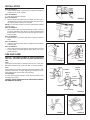
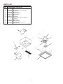
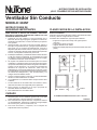
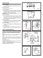
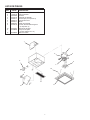
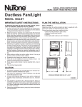
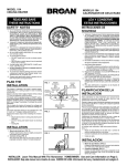
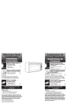
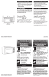
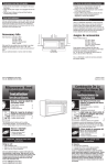
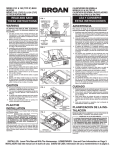
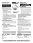
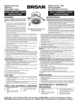
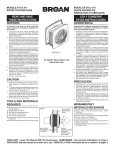
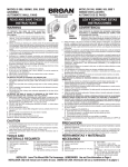
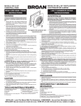
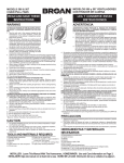
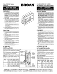
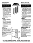
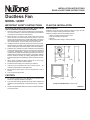
INSTALLATION INSTRUCTIONS
READ & SAVE THESE INSTRUCTIONS!
Ductless Fan
MODEL: 682NT
PLAN THE INSTALLATION
TO REDUCE THE RISK OF FIRE, ELECTRIC SHOCK, OR INJURY TO PERSONS, OBSERVE THE FOLLOWING:
1. Use this unit only in the manner intended by the manufacturer.
If you have questions, contact the manufacturer at the address
or telephone number listed in the warranty.
2. Before servicing or cleaning unit, switch power off at service
panel and lock the service disconnecting means to prevent
power from being switched on accidentally. When the service
disconnecting means cannot be locked, securely fasten a prominent warning device, such as a tag, to the service panel.
3. Installation work and electrical wiring must be done by a qualified person(s) in accordance with all applicable codes and standards, including fire-rated construction codes and standards.
4. Sufficient air is needed for proper combustion and exhausting
of gases through the flue (chimney) of fuel burning equipment
to prevent backdrafting. Follow the heating equipment
manufacturer’s guidelines and safety standards such as those
published by the National Fire Protection Association (NFPA),
and the American Society for Heating, Refrigeration and Air
Conditioning Engineers (ASHRAE), and the local code authorities.
5. When cutting or drilling into wall or ceiling, do not d a m a g e
electrical wiring and other hidden utilities.
6. Ducted fans must always be vented to the outdoors.
7. If this unit is to be installed over a tub or shower, it must be
marked as appropriate for the application.
8. Never place a switch where it can be reached from a tub or
shower.
9. This unit must be grounded.
Refer to FIGURE 1
Determine where fan will be located and plan to supply fan with
proper line voltage and appropriate power cable.
Follow these basic steps when installing this fan:
• Attach mounting bracket to joist or stud.
• Snap fan housing onto bracket.
• Wire fan.
• Attach grille (after ceiling or wall is finished).
7-1/8”
IMPORTANT SAFETY INSTRUCTIONS
7-1/8”
8-1/2”
6-1/4”
CAUTION
1. For general ventilating use only. Do not use to exhaust hazardous or explosive materials and vapors.
2. To avoid motor bearing damage and noisy and/or unbalanced
impellers, keep drywall spray, construction dust, etc., off power
unit.
3. Please read specification label on product for further information
and requirements.
8-1/2”
1”
ROUGH-IN OPENING SIZE IS 7-1/4” x 7-1/4”
FIGURE 1
INSTALLATION
Refer to FIGURE 2
1. Nail mounting bracket to joist or stud. Use gauge on bracket to
locate it for 1/2” or 3/4” drywall.
Refer to FIGURE 3
2. Snap fan housing onto bracket.
Refer to FIGURE 4
3. Remove the knockout plate from fan. Break out either top or
rear electrical access hole. Insert a screwdriver into slot in knockout and bend back and forth to break tabs.
NOTE: Turn off power and lock out service panel before installing
electrical wiring.
Refer to FIGURE 5
4. Secure power cable to knockout plate with proper connector
for type of cable being used. Allow 6” of cable to extend beyond
knockout plate. Connect ground wire to green ground screw on
knockout plate.
Refer to FIGURE 6
5. Make electrical connections. Wire white to white and black to
black.
Refer to FIGURE 7
6. Carefully tuck wiring inside wiring compartment and reattach
knockout plate.
Refer to FIGURE 8
7. Attach grille. Squeeze grille springs and insert them into slots
in motor plate. Push grille against ceiling. Grille may be papered or painted.
FIGURE 2
FIGURE 3
<
>
USE AND CARE
CAUTION – DISCONNECT POWER AT SERVICE ENTRANCE
AND LOCK OUT PANEL BEFORE CLEANING OR SERVICING
UNIT.
Grille
Clean grille with mild soap or detergent and dry with a soft cloth.
Do not use abrasive cloth, steel wool pads, or scouring powders.
Filter
Charcoal filter is long-lasting. Each filter will last 60 to 90 days when
operated continuously, or longer depending on frequency of use.
Order replacement charcoal filter from list below.
Fan Assembly
To clean: Remove grille and filter. Gently vacuum impeller, motor
and interior of housing.
CAUTION – METAL AND ELECTRICAL PARTS SHOULD NEVER
BE IMMERSED IN WATER.
FIGURE 4
FIGURE 5
WHITE
TOGGLE
SWITCH
HOUSING
SWITCH
BOX
BLACK
BLACK
WHITE
GROUND
BLACK
120 VAC LINE IN
FIGURE 6
FIGURE 7
2
FIGURE 8
PARTS LIST
REF.
PART
NUMBER
1
2
3
4
5
6
7
8
9
20125-00
75999-00
99270982
20126-02
04200-14
25083-01
02200-41
99020187
03100-32
10
11
99140187
97009648
12
97009563
PART DESCRIPTION
Mounting Bracket
Knockout Plate & Ground Screw
Receptacle
Wiring Cover
Keps Nut (2 Req.)
Motor Bracket
Motor
Fan Blade
Screw, #8 Hex Washer Captive Hd.
(3 Req.)
Grille Spring
Grille Assembly
(Includes Key Nos. 10 & 11)
Charcoal Filter
1
5
6
9
2
8
7
10
3
12
11
4
3
WARRANTY
NUTONE ONE YEAR LIMITED WARRANTY
NuTone warrants to the original consumer purchaser of our products that such products will be free from defects in materials or
workmanship for a period of one year from date of original purchase. THERE ARE NO OTHER WARRANTIES, EXPRESSED OR
IMPLIED, INCLUDING, BUT NOT LIMITED TO, IMPLIED WARRANTIES OR MERCHANTABILITY OR FITNESS FOR A PARTICULAR PURPOSE.
During this one-year period, NuTone will, at our option, repair or replace, without charge, any product or part which is found to be
defective under normal use and service.
THIS WARRANTY DOES NOT EXTEND TO FLUORESCENT LAMP STARTERS AND TUBES. This warranty does not cover (a)
normal maintenance and service or (b) any products or parts which have been subject to misuse, negligence, accident, improper
maintenance or repair (other than by us), faulty installation or installation contrary to recommended installation instructions.
The duration of any implied warranty is limited to the one-year period as specified for the express warranty. Some states do not allow
limitation on how long an implied warranty lasts, so the above limitation may not apply to you.
NUTONE’S OBLIGATION TO REPAIR OR REPLACE, AT OUR OPTION, SHALL BE THE PURCHASER'S SOLE AND EXCLUSIVE
REMEDY UNDER THIS WARRANTY. NUTONE SHALL NOT BE LIABLE FOR INCIDENTAL, CONSEQUENTIAL OR SPECIAL DAMAGES ARISING OUT OF OR IN CONNECTION WITH PRODUCT USE OR PERFORMANCE. Some states do not allow the exclusion
or limitation of incidental or consequential damages, so the above limitations or exclusion may not apply to you.
This warranty gives you specific legal rights, and you may also have other rights, which vary from state to state. This warranty supersedes all prior warranties.
To qualify for warranty service, you must (a) notify us at an address stated below or telephone 1-888-336-6151, (b) give the model
number and part identification and (c) describe the nature of any defect in the product or part. At the time of requesting warranty service,
you must present evidence of the original purchase date.
NUTONE, INC.
A Nortek Company
Madison and Red Banks Roads
Cincinnati, OH 45227
Product specifications subject to change without notice.
Madison and Red Bank Roads, Cincinnati, Ohio 45227
Printed in U.S.A., 11/99, Part No. 99042928A
INSTRUCCIONES DE INSTALACIÓN
¡LEA Y CONSERVE ESTAS INSTRUCCIONES!
Ventilador Sin Conducto
MODELO: 682NT
Refiera a la FIGURA 1
Determine donde estará ubicada la unidad y suminístrele la tensión
de línea y cable de energía eléctrica correctos.
Al instalar este ventilador/luz, siga estos pasos básicos:
• Enganche el soporte de montaje a la viga de pared o
cielo raso.
• Enganche la caja en el soporte.
• Haga el cableado de la unidad.
• Enganche la rejilla (después que esté terminado el cielo rasoo
pared).
18,10cm
PARA REDUCIR EL RIESGO DE INCENDIO, DESCARGA
ELÉCTRICA O LESIONES PERSONALES, CUMPLA CON LAS
SIGUIENTES INSTRUCCIONES:
1. Solamente use esta unidad en la forma propuesta por el
fabricante. Si tiene alguna pregunta, póngase en contacto con
el fabricante en la dirección o número de teléfono que aparece
en la garantía.
2. Antes de limpiar o de poner en servicio la unidad, apague el
interruptor en el panel de servicio, y asegure el panel de servicio
para evitar que se encienda accidentalmente. Cuando el
dispositivo para desconectar el servicio eléctrico no puede ser
cerrado con algún tipo de traba, sujete fuertemente al panel de
servicio, una etiqueta de advertencia prominente.
3. El trabajo de instalación y el alambrado eléctrico deben llevarse
a cabo por personal competente, de conformidad con todos
los códigos y normas correspondientes, incluyendo los códigos
y normas de construcción contra incendios.
4. Se requiere una cantidad de aire suficiente para una correcta
combustión y expulsión de gases por la chimenea del conjunto
que quema combustible para evitar la retrogresión de la llama.
Cumpla con las directrices y las normas de seguridad del
fabricante de conjuntos de calefacción, tales como las
publicadas por la Asociación Nacional de Protección Contra
Incendios (NFPA) y la Asociación Norteamericana de Ingenieros
de Calefacción, Refrigeración y Aire Acondicionado, y los
códigos de las autoridades locales.
5. Al cortar o perforar la pared o cielo raso, no dañe el alambrado
eléctrico ni otras instalaciones no visibles.
6. Los ventiladores con conductos deben siempre extraer hacia
el exterior.
7. Si esta unidad se ha de instalar sobre una bañera o ducha,
debe estar marcada como apropiada para la aplicación.
8. Nunca coloque un interruptor en un lugar que pueda ser
alcanzado desde una bañera o ducha.
9. Esta unidad debe ser conectada a tierra.
PLANIFICACION DE LA INSTALACION
18,10cm
9,53cm
21,59cm
INSTRUCCIONES DE
SEGURIDAD IMPORTANTES
21,59cm
2,54cm
CUIDADO
EL TAMAÑO DE ABERTURA ES DE 18,42cm x 18,42cm
1. Solamente para uso de ventilación general. No lo use para
extraer materiales y vapores peligrosos o explosivos.
2. Para evitar daños al cojinete del motor e impulsores ruidosos
y/o desequilibrados, mantenga la unidad de energía alejada
de rocíos de yeso, polvo de construcción, etc.
3. Para más información y requisitos, lea la etiqueta de
especificación sobre el producto.
FIGURA 1
INSTALACION
Refiera a la FIGURA 2
1. Clave el soporte de montaje a la viga de pared o cielo raso.
Use el calibrador en el soporte para situarlo en pared de yeso
de 1,27 cm o 1,90 cm.
Refiera a la FIGURA 3
2. Enganche la caja en el soporte.
Refiera a la FIGURA 4
3. Saque de la caja la placa del disco removible. Saque la placa
del agujero de acceso ya sea de la parte superior o de atrás.
Meta un destornillador en la ranura del disco removible y doble
para atrás y adelante para romper lengüeta.
ADVERTENCIA: Corte la energía en el panel de servicio y
asegúrelo antes de instalar el cableado eléctrico.
Refiera a la FIGURA 5
4. Fije el cable de energía eléctrica a la placa de disco removible
con el conector correcto para el tipo de cable que se está
utilizando. Deje que 15,24 cm de cable salgan de la placa de
disco removible. Conecte el conductor de tierra al tornillo verde
de tierra en la placa del disco removible.
Refiera a la FIGURA 6
5. Quite uno de los discos removibles eléctricos y conecte el cable
de energía eléctrica a la caja del ventilador usando el conector
apropiado. Conecte negro a negro y blanco a blanco
Refiera a la FIGURA 7
6. Coloque cuidadosamente el cableado dentro del
compartimiento de cableado y vuelva a fijar la placa del disco
removible.
Refiera a la FIGURA 8
7. Fije la rejilla. Presione los resortes de la rejilla y métalos en las
ranuras de la placa del motor. Empuje la rejilla contra el cielo
raso.
FIGURA 2
FIGURA 3
<
>
FIGURA 4
USO Y MANTENIMIENTO
CUIDADO – DESCONECTE EL SUMINISTRO DE ENERGÍA
ELÉCTRICA EN LA ENTRADA DE SERVICIO ANTES DE
EFECTUAR LA LIMPIEZA, O DAR SERVICIO A LA UNIDAD.
Rejilla
Limpie la rejilla con jabón suave y seque con un paño suave. No
use paños ásperos, lana de acero o polvos de fregado.
Filtro
El filtro de carbón es duradero. Cada filtro dura de 60 a 90 días
cuando se le usa en forma continua, o más tiempo, lo que dependerá
de la frecuencia de uso. Encargue el filtro de carbón de repuesto
de lista abajo.
Conjunto Del Ventilador
Para limpiar: quite la rejilla y filtro. Con cuidado pase aspiradora
por el impulsor, motor e interior de la caja.
CUIDADO – LAS PIEZAS METALICAS Y ELECTRICAS NUNCA
SE DEBEN SUMERGIR EN EL AGUA.
BLANCO
CAJA
FIGURA 5
CONMUTADOR
DE PALANCA
ACODILLADA
CAJA DE
INTERRUPTORES
NEGRO
NEGRO
BLANCO
TIERRA
NEGRO
120 VCA LINEA
DE ENTRADA
FIGURA 6
FIGURA 7
6
FIGURA 8
LISTA DE PIEZAS
REF.
NO. DE
PIEZAS
1
2
3
4
5
6
7
8
9
20125-00
75999-00
99270982
20126-02
04200-14
25083-01
02200-41
99020187
03100-32
10
11
99140187
97009648
12
97009563
DESCRIPCION
Soporte de montaje
Placa removible
Enchufe
Cubierta de cableado
Tuerca keps (se requieren 2)
Soporte del motor
Motor
Aleta del ventilador
Tornillo, #8 arandela hexagonal
(se requieren 3)
Resorte de la rejilla
Conjunto de rejilla
(Incluye códigos 10 & 11)
Filtro de carbón
1
5
6
9
2
8
7
10
3
12
11
4
7
GARANTIA
GARANTIA NUTONE LIMITADA POR UN AÑO
NuTone garantiza al consumidor comprador original de sus productos que dichos productos carecerán de defectos en materiales o en
mano de obra por un período de un año a partir de la fecha original de compra. NO EXISTEN OTRAS GARANTIAS, NI EXPLICITAS
NI IMPLICITAS, INCLUYENDO, PERO NO LIMITADAS A, GARANTIAS IMPLICITAS DE COMERCIALIZACION O APTITUD PARA
UN PROPOSITO PARTICULAR.
Durante el período de un año, y a su propio criterio, NuTone reparará o reemplazará, sin costo alguno, cualquier producto o pieza que
se encuentre defectuosa bajo condiciones normales de servicio y uso.
ESTA GARANTIA NO SE APLICA A TUBOS Y ARRANCADORES DE LAMPARAS FLUORESCENTES. Esta garantía no cubre (a)
mantenimiento y servicio normales ni (b) cualquier producto o piezas que hayan sido utilizadas de forma errónea, negligente, que
hayan tenido un accidente, o que hayan sido reparadas o mantenidas incorrectamente (por otras compañías que no sean NuTone),
instalación defectuosa, o instalación contraria a las instrucciones de instalación recomendadas.
La duración de cualquier garantía implícita se limita a un período de un año como se especifica en la garantía expresa. Algunos
estados no permiten limitaciones en cuanto al tiempo de expiración de una garantía implícita, por lo que la limitación antes mencionada
puede no corresponderle.
LA OBLIGACION DE NUTONE DE REPARAR O REEMPLAZAR, SIGUIENDO EL CRITERIO DE NUTONE, DEBERA SER EL UNICO
Y EXCLUSIVO RECURSO LEGAL DEL COMPRADOR BAJO ESTA GARANTIA. NUTONE NO SERA RESPONSABLE POR DAÑOS
INCIDENTALES, CONSIGUIENTES, O POR DAÑOS ESPECIALES RESULTANTES A RAIZ DEL USO O DESEMPEÑO DEL
PRODUCTO.
Algunos estados no permiten la exclusión o limitación de daños incidentales o consiguientes, por lo que la limitación antes mencionada
puede no aplicarse a usted.
Esta garantía le proporciona derechos legales específicos, y usted puede también tener otros derechos, los cuales varían de estado
a estado. Esta garantía reemplaza todas las garantías anteriores.
Para tener derecho al servicio de garantía, usted debe (a) notificar a NuTone en la dirección que se menciona abajo o al teléfono:1-888336-6151 en los E.E. U.U., (b) dar el número del modelo y la identificación de la pieza, y (c) describir la naturaleza de cualquier defecto
en el producto o pieza. En el momento de solicitar servicio cubierto por la garantía, usted debe presentar comprobación de la fecha
original de compra.
NUTONE, INC.
A Nortek Company
Madison and Red Banks Roads
Cincinnati, OH 45227
Especificaciones de producto conforme a cambio sin el aviso.
Madison and Red Bank Roads, Cincinnati, Ohio 45227
Printed in U.S.A., 11/99, Part No. 99042928A