1
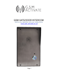
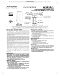
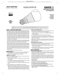
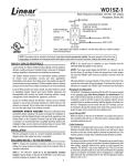
Codesetting Instructions for D-21, 24, 26 (/K)
Linear P/N: 200105 C
Size: 11.50" W x 5.75" H
Ink: PMS 285 (Blue) & Black
Material: 70 Lb. White Coated
DESCRIPTION
The D-21A(/K), D-24A(/K), and D-26A(/K) are
digitally coded stationary radio transmitters
triggered by normally open (N/O) or normally
closed (N/C) sensors. These transmitters can
be programmed to activate any of Linear’s
standard digital receivers that are tuned to the
same frequency. Each transmitter can perform
many remote switching tasks and are typically
used in wireless/hardwire security systems.
Each unit is powered by a self-contained 9-volt
battery and can be connected to various
sensors with the built-in screw terminals.
time delay of 1 to 3 seconds, ensuring that the
sensor circuit must be continuously open for at
least 1 second before the D-24A will transmit.
This feature helps prevent activation from
short-term, spurious signals, and from signals
made from outside electromagnetic sources.
The transmitter may be re-triggered after a
30-second reset time. The transmitter has a
pushbutton for battery/transmission test.
NOTE: Transmitters with a /K model number
suffix are Linear’s Canadian models tuned to 318
MHz. These instructions pertain to both the /K
and standard 303.875 MHz U.S. models.
D-21A N/O TRANSMITTER
The D-21A is used with various types of security
sensors that are normally open (magnetic
contacts, security floor mats, etc.). The D-21A
transmits a signal when the sensor circuit
closes. The transmitter triggers instantly, and
may be re-triggered after a 30-second reset time.
A pushbutton is provided for battery/transmission
test. Pressing the pushbutton with the sensor
circuit open (after the 30-second reset) triggers
the transmitter and turns on the red LED if the
battery is above 7.5 volts.
D-26A N/O TIME-DELAY TRANSMITTER
The D-26A is used with various types of security
sensors that are normally open. The
special-purpose D-26A transmitter has a built-in
exit/entry time delay. The timer starts when the
sensor circuit closes. It begins a 5 to 10 second
countdown. If no action is taken before the time
delay is completed, the transmitter will send an
alarm signal to its companion receiver. Pressing
the pushbutton before the time delay period
has elapsed will prevent signal transmission.
In addition to canceling time-delayed signal
transmission, the pushbutton is used to test the
battery. Pressing the button turns on the red
LED if the battery is in good condition. The LED
does not light upon transmission.
D-24A N/C TRANSMITTER
The D-24A is used with various types of security
sensors that are normally closed (magnetic
contacts, security window screens, etc.). The
D-24A transmits a signal when the sensor
circuit opens. The transmitter incorporates a
NOTE: The each transmitter contains a timing
circuit that allows a single transmission of a
2-second duration to occur, followed by a
30-second reset time. This means that regardless
of the number of times the transmitter is triggered,
it will not send a signal more often than once every
30 seconds.
Codesetting Instructions for D-21, 24, 26 (/K)
Linear P/N: 200105 C
Size: 11.50" W x 5.75" H
Ink: PMS 285 (Blue) & Black
Material: 70 Lb. White Coated
CODE SWITCH LOCATION
The digital coding switch is attached to the circuit
board inside the case. To access the switch,
unsnap and slide off the back cover as shown in
Figure 1, exposing the battery, lead wire screw
terminals, and digital coding switch (see Figure 2).
Use a pointed object (other than a pencil or pen)
to set the keys. The ON position is when the top
of the switch is down, facing the numbers. The
OFF position is when the top of the switch is up
and the bottom is down, away from the numbers.
In the example shown in Figure 3, keys 1,4,6
and 8 are ON; keys 2,3,5 and 7 are OFF.
Figure 1.
Removing
the
Transmitter
Back Cover
NOTE: On the D-24A, the loop input terminals
must be closed for a minimum of 45 seconds
before the pushbutton will activate the
transmitter.
MOUNTING
SCREWS
8
7
6
5
4
3
2
N
O
1
RECESSED
WIRING
HOLE
F
F
O
CODING
SWITCH
9-VOLT
BATTERY
Figure 2.
Transmitter
Components
SCREW
TERMINALS
CODE SETTING
CAUTION! All transmitters and receivers must be
re-coded by installer prior to operation. DO NOT
USE THE FACTORY SET CODE!
Among the 256 possible codes, four codes are
considered invalid, and should not be used. They
are: all keys ON, all keys OFF, and keys set
alternating ON/OFF or OFF/ON combinations.
To set a code, select any valid combination of
ON and OFF positions for the switch keys
numbered 1 through 8.
SURFACE
WIRING
SLOT
Figure 3. Example
Coding Switch
Figure 4. Transmitter
Back Cover Mounting
INSTALLATION
To mount the transmitter, proceed as follows:
STEP 1: Select a location for the transmitter and
drive screws through the two countersunk holes of
the back cover to mount the cover (see Figure 4).
NOTE: Generally, the higher the transmitter is
mounted above ground level (minimum of 3
feet) the better the radio range should be.
STEP 2: For recessed switches with hidden
wiring, fish the sensor wires through the wire
access hole on the back cover. With surface
wiring, route the wire leads through the wire slot
on the back cover (see Figure 4).
Codesetting Instructions for D-21, 24, 26 (/K)
Linear P/N: 200105 C
Size: 11.50" W x 5.75" H
Ink: PMS 285 (Blue) & Black
Material: 70 Lb. White Coated
STEP 3: Attach wires from the sensor switch to
the transmitter screw terminals. Wire normally
closed switches in series, and normally open
switches in parallel (see Figures 5 & 6).
NOTE: A maximum of wire run of 50 feet with
a total of four switches may be used with one
transmitter.
Figure 5.
Normally
Open
Switch
Wiring
Figure 6.
Normally
Closed
Switch
Wiring
STEP 4: Slide the transmitter onto the back
cover until locked into place to complete
installation (see Figure 7).
CHECKOUT AND TEST
After installation, the transmitter and receiver
should be checked out as a system.
Activate the transmitter by triggering the sensor.
Verify that the LED lights when the sensor is
triggered (except for D-26A). Receiver
activation indicates that the transmitter is
Codesetting Instructions for D-21, 24, 26 (/K)
Linear P/N: 200105 C
Size: 11.50" W x 5.75" H
Ink: PMS 285 (Blue) & Black
Material: 70 Lb. White Coated
LINEAR LIMITED WARRANTY
Figure 7.
Typical
Installation
(Door and
Window)
operating properly, and that the transmitter’s
digital code is correctly matched to the code set
in the receiver.
CAUSES FOR NON-OPERATION
If the transmitter fails to activate the receiver,
first check the coding switches to see that the
switch keys in the transmitter and the receiver
are correctly matched. Next, check the battery
and replace it if it’s weak.
If the code is set correctly, the battery is good,
and the LED lights but the receiver dosen’t
activate, check for hidden metal obstacles or
large metal appliances between the transmitter
and receiver that may be blocking the radio
signal. Re-location of the transmitter or receiver
may be necessary
C A U T I O N : T h e m a n u f a c t ure r s t rongly
recommends that you test security equipment
frequently. From the time of installation, it is
absolutely necessary to test the system at
least once a week. Although the 9-volt battery
should last about a year, it is good practice to
change the battery every six months.
This Linear product is warranted against defects in material and
workmanship for twelve (12) months. The Warranty Expiration Date is
labeled on the product. This warranty extends only to wholesale
customers who buy direct from Linear or through Linear’s normal
distribution channels. Linear does not warrant this product to
consumers. Consumers should inquire from their selling dealer as to the
nature of the dealer’s warranty, if any. There are no obligations or
liabilities on the part of Linear corporation for consequential damages
arising out of or in connection with use or performance of this product
or other indirect damages with respect to loss of property, revenue,
or profit, or cost of removal, installation, or reinstallation. All implied
warranties, including implied warranties for merchantability and implied
warranties for fitness, are valid only until Warranty Expiration Date as
labeled on the product. This Linear Corporation Warranty is in lieu of
all other warranties express or implied.
D-21A, D-21A/K,
D-24A, D-24A/K,
D-26A, D-26A/K
Digital Security
Transmitters
For warranty service on Linear equipment return product, at sender’s
expense to:
U.S.A.
Linear Corporation
2350 Camino Vida Roble, Suite A
Carlsbad, CA 92009
Attn: Repairs Department
Canada
Linear Canada Inc.
673 Consortium Court
London, Ontario, Canada N6E 2S8
Attn: Repairs Department
IMPORTANT !!!
Linear radio controls provide a reliable communications link and fill an
important need in portable wireless signalling. However, there are some
limitations which must be observed.
For U.S. installations only: The radios are required to comply with
FCC Rules and Regulations as Part 15 devices. As such, they have
limited transmitter power and therefore limited range.
Receivers may be blocked by radio signals that occur on or near
their operating frequencies, regardless of code settings.
A receiver cannot respond to more than one transmitted signal at a time.
Code Setting and
Installation Instructions
Infrequently used radio links should be tested regularly to protect
against undetected interference or fault.
A general knowledge of radio and its vagaries should be gained
prior to acting as a wholesale distributor or dealer, and these facts
should be communicated to the ultimate users.
Copyright © 1992 Linear Corporation
200105 C
A NORTEK COMPANY