1
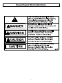
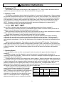
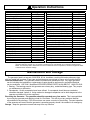
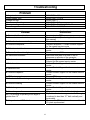
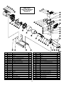
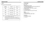
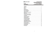
M165951C
Item Number:
165951
Serial Number:
TM
OWNER’S MANUAL
7800 PTOG: 7800 Watt Power Take-Off Generator
WARNING
Read this manual.
Serious injury or death can result if safety instructions are not followed.
DANGER
DANGER
Any Questions, Comments, Problems or Parts Orders
Call NorthStar Product Support 1-800-270-0810
1
Hazard Signal Word Definitions
2
Table of Contents
Important Safety Rules ..............................……. 4
Warning Label Locations .............................…… 5
Unpacking ......................................................……. 6
Assembly ....................................................………. 6
Machine Component Identification...........…………. 7
Installation ................................................……... 8
Operation Instructions...................................…... 9-11
Maintenance and Storage.......................………….. 11
Troubleshooting ............................................…….. 12
Specifications and Accessories........................…… 13
Parts Explosion ..............................................……. 14-15
3
Important Safety Rules
TRAINING AND INSTALLATION
WARNING:
1. Read the Operator’s Manual completely before attempting to use the generator. Serious injury or death can result if
safety instructions are not followed.
2. Do not allow anyone to operate the generator who has not read the Operator’s Manual or has not been instructed on
the safe use of the generator.
3. Never allow anyone under 16 years old or untrained adults operate the generator. Children 16 years and older must
be trained and supervised by a trained adult.
4. Read and follow all safety rules in the tractor’s Operator’s Manual.
5. Never operate in an enclosure or building. Fire or explosion will result.
6. Keep a fire extinguisher close by your generator and be familiar with how to use it. Consult your local fire department
for correct extinguisher type.
7. Always keep the generator and the area around the generator clean.
8. Never mount to a trailer that is not wide enough to handle operating torque. Trailer may tip and cause injury or death.
9. Never connect generator to another electrical system without a licensed electrician installed isolation transfer switch.
OPERATION
WARNING:
1. Before starting this generator, review the “Operation Instructions” section of this manual. Failure to follow these rules
may result in serious injury to the operator or bystanders.
2. Always provide adequate ventilation. Do not operate generator in any enclosed or narrow space. Tractors consume
oxygen and give off deadly carbon monoxide, a poisonous gas that can kill you.
3. Never operate the generator without proper guarding, including driveline guards and tractor and generator shields.
4. Always securely attach the driveline at both ends and keep the driveline guard from rotating freely on the driveline.
5. Never operate the generator when the PTO driveline is at an angle greater than 15° either horizontally or vertically.
6. Never operate the generator while wearing loose fitting clothing such as neckties, scarves, or untucked shirts.
7. ELECTRIC SHOCK HAZARD:
A. This generator is equipped with a grounding screw located on the generator frame. Always complete the
grounding path from the generator to a copper pipe/rod that is driven into moist earth to prevent electric shock.
B. Always use grounded male plugs. The neutral line of the generator is mechanically grounded to the frame.
Matching NEMA male plugs must always be used. Electric shock could result.
C. Always use electrical cords in good condition. Worn, bare, frayed or damaged cords can cause electric shock.
D. Always use a ground fault circuit interrupter (GFCI) in damp or highly electrical conductive areas and on
construction job sites to prevent electric shock.
E. Never operate the generator, or handle any electrical equipment while standing in water, while barefoot, while
hands are wet or while in the rain or snow. Electric shock may result.
8. Always wear ear protection while operating generator.
9. Never operate the generator under the following conditions:
A. Overheating in load connecting devices.
B. Sparking or arcs from generator.
C. Loss of electrical output.
D. Damaged receptacles.
E. Loose, broken, or missing parts.
F. Excessive vibration.
G. Enclosed compartments, or confined areas.
H. Flame or smoke.
I. Rain, snow, or wet conditions.
J. Operator non-attendance or without proper guarding in place.
MAINTENANCE AND STORAGE
WARNING:
1.
2.
3.
4.
5.
6.
Refer to the “Maintenance and Storage” section of this manual for proper procedures.
Always remove PTO driveline before working on the generator.
Clear debris from moving parts when the tractor is shut off. This will ensure the generator is in safe working condition.
Check that all nuts and bolts are tight to assure the generator is in safe working condition.
Make sure all guards and shields are replaced after maintenance is complete.
If a part needs replacement, only use parts that meet the manufacturer's specifications. Replacement parts that do not
meet specifications may result in a safety hazard or poor operation of the generator.
7. Never modify the generator in any way, modifications may create a safety hazard and result in serious injury.
4
Warning Label Locations
DANGER!
ROTATING DRIVELINE−CONTACT CAN CAUSE DEATH.
NEVER OPERATE WITHOUT:
WARNING!
305545
ELECTRICAL SHOCK CAN KILL.
ALWAYS ground generator.
NEVER connect generator to another electrical system without
an isolation transfer switch installed by a licensed electrician.
WARNING!
NEVER operate generator in an
enclosed area. (Exhaust gases
contain carbon monoxide, an
odorless and deadly poison.)
NEVER refuel a hot or running
engine.
NEVER operate generator
without proper guarding.
NEVER operate generator with
loose, broken or missing parts.
NEVER operate generator under
wet conditions, electric shock
may occur.
ALWAYS clean up fuel spills and
move generator away from the
spill before starting engine.
Call 1-800-270-0810 to order new labels.
Warning: General Rules
Part No. 777131
Danger: Rotating Driveline
Part No. 31696
Warning: Electric Shock
Part No. 305545
5
Unpacking
Closely inspect all contents in the shipping carton.
- If you have damaged components: Contact the freight company that delivered the unit and file a claim.
- If you have missing components: Contact Product Support at 1-800-270-0810.
Assembly
The gearbox is shipped with oil. Remove the shipping plug and install the filler/breather plug. Make sure that
the gear oil level is in the middle of the sight glass; add SAE 80W-90 gear oil as required.
Filler/Breather plug
Shipping plug
Sight glass
6
Machine Component Identification
1. Alternator. Also called generator
head.
2. Grounding Screw. Use to ground
the generator to a copper pipe or rod
that is driven into moist soil.
3. Isomounts. Reduces vibrations
transmitted to the control box
4. 30A Circuit Breaker. Thermal
magnetic breaker protects against
overcurrents and short circuits.
5. 120V Receptacles. One 120V 20A
straight blade receptacle duplex (two
receptacles in a common housing).
National Electrical Manufacturer’s
Association (NEMA) number 5-20R.
6. 20A Circuit Breaker. (Qty 2) Push
to reset style thermal breakers
protect against overcurrents.
7. 120/240V Locking Receptacle. 30A
receptacle, NEMA L14-30R.
8. Gearbox. 1:7 gear ratio.
9. Filler/Breather Plug. Fill oil here;
use SAE 80W-90 gear oil.
10. Implement shield. Never operate
generator without shield in place.
11. Fan Vents. Never block the vent
slots or insert objects through the
slots. The closest object should be
at least 3 feet away from the vents.
12. Mounting Holes. Use these
locations to mount the generator in
place with 5/8” grade 5 bolts.
13. Voltmeter. Needle should be in
green area during all generator load
conditions. The black line in the
center of the green area indicates
120V. During no load conditions,
the needle should be at or above the
black line.
14. 1-3/8” Diameter 6 Spline Input
Shaft. Requires 14 HP or greater at
540 RPM.
15. Oil Fill Sight Glass. When oil is
even with the red dot, the oil level is
correct. Check oil level daily.
16. Oil Drain Plug. Remove to drain oil
from gearbox.
7
Installation
Choose a location where the generator will not be exposed to rain, snow or direct sunlight. Common
places for mounting your PTO generator are to a trailer or a cement slab. Make sure it is as close to the load
as possible. This will make using the generator more convenient and reduce voltage drop.
The installation site must be free from water, moisture, or dust. Foreign matters, such as dust, dirt, sand,
lint, or abrasive materials can cause damage if allowed inside the generator. All electrical components should
be protected from excessive moisture or the insulation system will deteriorate and result in shorting out of the
generating system.
1. Mounting the PTO generator to a trailer.
Use four(4) 5/8” grade 5 bolts to secure the PTO
generator to the trailer.
Important: When trailer mounting the generator, select
a trailer that is wide enough to withstand the torque of
start-up and loading torque. Wheels that are not
spaced properly could cause the trailer to tip over. The
constant vibration of the generator can cause metal
fatigue of the trailer base if the steel used is not thick
enough. A PTO trailer is available from Northern,
Item# 165959. Call 1-800-556-7885 to order.
WARNING DANGER PTO trailer or generator
may tip over and cause serious injury or death. Never
stand near an operating PTO generator. Always bolt
Mounting holes (4)
PTO base to a secure foundation or mounting slab.
2. Mounting the PTO generator to
concrete.
Use four(4) 5/8” grade 5 anchor bolts when mounting
the generator on a cement slab.
Max. 15°
3. Connecting the PTO generator to a tractor.
After the generator is firmly mounted, attach the PTO
driveline to the generator then the tractor. Use a
synchronized PTO driveline rated at 14 HP minimum.
A PTO driveline is available from Northern,
Item# 165936. Call 1-800-556-7885 to order.
Important: The angle of the driveline shall not exceed
15o in either the horizontal or vertical plane.
Top View
Driveline
Max. 15°
WARNING Always properly guard rotating parts.
Failure to guard the power transmission mechanisms
may result in serious injury or death.
Side View
4. Grounding
This unit must be grounded. Drive a 3/4” or 1” copper pipe or rod into the ground near the generator. It must
penetrate moist earth. Connect an approved ground clamp to the pipe. Run an 8 gauge copper wire from the
clamp to the generator ground screw. Do not connect to a water pipe or a ground used by a radio system.
WARNING Always ground the generator. Electrical shock can kill.
5. Standby Use
If your generator is to be used as a standby electric power source in case of utility failure, it must be installed
by a registered and licensed electrician and in compliance with all applicable state and local electrical codes.
WARNING Never connect any generator to any existing electrical system without an isolating, UL
approved transfer switch installed by a licensed electrician.
8
Operation Instructions
1. Engaging the PTO
While seated on the tractor and the engine at idle, engage the PTO. Slowly increase the throttle until the
needle in the generator voltmeter is at or above the black line in the green area.
2. Applying a Load
It is important to determine the total electrical load before it is connected to the generator. Always compare
the generator nameplate data with that of the equipment to be used to ensure that watts, volts, amperage, and
frequency requirements are suitable for operating equipment. The wattage listed on the equipment nameplate
is its rated output. However, some equipment may require three to ten times more wattage than its rating on
the nameplate, as the wattage is influenced by the equipment efficiency, power factor and starting system.
NOTE: If wattage is not given on equipment nameplate, approximate wattage may be determined by
multiplying nameplate voltage by nameplate amperage.
VOLTS X AMPS = WATTS
Example: 120V X 5A
= 600W
Also, a chart of estimated load requirements for some appliances and tools is shown on page 11.
When connecting a resistive load such as incandescent lights, heaters or common electric power tools, a
capacity of up to the generator full rated wattage output can be used.
When connecting a resistive-inductive load such as a fluorescent or mercury light, transformers or inductive
coils, a capacity of up to 0.6 times the generator’s full rated output can be used.
Always allow the generator to reach operating speed before a load is applied.
Important: The two major factors in determining the life of a generator head are heat build up caused by
overloading the generator and corrosive contaminants that attack the wiring insulation. If the generator is
overloaded, the wires become excessively hot and cause the insulation to break down, reducing its ability to
resist corrosive contaminants. Over time the effectiveness of the insulation is eliminated and a dead short can
result.
Apply the load to the generator. Remember to stay clear of the rotating PTO driveline. From the tractor
seat re-adjust the speed until the needle on the generator voltmeter is close to the black line in the green area.
If the needle will not rise to the green area no matter what the engine speed, the generator is either overloaded
or there is a problem. Use the troubleshooting guide at the end of the manual for assistance with possible
problems.
3. Operating Speed
The generator must be run at the correct speed in order to produce the proper electrical voltage and
frequency.
The output voltage should be checked to ensure the generator is working properly subsequent to
connecting a load to the generator. Failure to do so could result in damage to equipment plugged into the unit
and possible injury to the individual.
All engines have a tendency to slow down when a load is applied. When the electrical load is connected to
the generator, the engine is more heavily loaded, and as a result the speed drops slightly. This slight decrease
in speed, together with the voltage drop within the generator itself, results in a slightly lower voltage when the
generator is loaded to its full capacity than when it is running with no load. The slight variation has no
appreciable effect in the operation of motors, lights and most appliances. Electronic equipment and clocks will
be affected if correct RPM is not maintained. See Load vs. Output chart.
Output voltage should be checked periodically to
Load
Output
ensure continued proper operation of the generator
Percent of Speed Frequency
Generator
and appliances. It can be checked with a portable
Generator (RPM)
(Hz)
Voltage at 120V
meter. Frequency can be checked by using an electric
Output
Receptacle
clock with a sweep second hand. Timed against a
0%
3780
63.0
125V
wristwatch or a stopwatch the clock should be correct
50%
3600
60.0
122V
within +/- 2 seconds per minute. All speed setting
100%
3480
58.0
118V
adjustments should be done by a qualified technician.
9
Operation Instructions
4. Starting Electric Motors
Electric motors require much more current
(amps) to start than to run. Some motors,
particularly low cost split-phase motors, are
very hard to start and require 5 to 7 times more
120V, 60 Hz Motors
Starting Amps
current to start than to run. Capacitor motors
HP Motor
Running
RI Type
Cap Type
SP Type
are easier to start and usually require 2 to 4
Watts
times as much current to start than to run.
1/6
525
7-11
9-18
16-22
Repulsion Induction motors are the easiest to
¼
700
9-15
12-23
22-32
start and require 1.5 to 2.5 times as much to
1/3
875
11-18
14-29
26-35
½
1175
15-25
20-40
NA
start than to run.
1
1925
24-40
32-64
NA
Most fractional motors take about the same
1
½
2400
30-50
40-80
NA
amount of current to run whether they are of
2
1900
36-60
48-96
NA
Repulsion-Induction (RI), Capacitor (Cap), or
3
4075
51-85
68-136
NA
Split-Phase (SP) type. The chart shows the
5
6750
84-140
112-124
NA
approximate current required to start and run
various types and sizes of 120 volt 60 cycle
electric motors under various conditions.
The figures given above are for an average load such as a blower or fan. If the electric motor is
connected to a hard starting load such as an air compressor, it will require more starting current. If it is
connected to a light load or no load such as a power saw, it will require less starting current. The exact
requirement will also vary with the brand or design of the motor.
Generators respond to severe overloading differently than power lines. When overloaded, the engine is
not able to supply enough power to bring the electric motor up to operating speed. The generator responds
to the high initial starting current, but the engine speed drops sharply. The overload may stall the engine. If
allowed to operate at very low speeds, the electric motor starter winding will burn out in a short time. The
generator head winding might also be damaged.
Running the generator under these conditions may result in damage to the generator stator as well as the
electric motor windings. Because the heavy surge of current is required for only an instant, the generator will
not be damaged if it can bring the motor up to speed in a few seconds. If difficulties in starting a motor are
experienced, turn off all other electrical loads and if possible reduce the load on the electric motor.
5. Extension Cords
When electric power is to be provided to
various loads at some distance from the
generator, extension cords can be used.
These cords should be sized to allow for
distance in length and amperage so that the
voltage drop between the generator and point
of use is held to a minimum.
CAUTION: Equipment damage can result from
the low voltage caused by using an extension
cord with a small wire size.
Current/Power
Amps
Load
at
(Watts)
240V
10
2400
20
4800
30
7200
40
9600
50
12000
Maximum Extension Cord Length
#10 Ga
#12 Ga
#14 Ga #16 Ga
Cord
Cord
Cord
Cord
250’
125’
60’
30’
15’
150’
75’
35’
15’
*
100’
75’
50’
25’
25’
10’
10’
*
*
*
*Not Recommended
WARNING Keep a fire extinguisher close by your generator and be familiar with how to use it. Consult
your local fire department for correct extinguisher type.
10
Operation Instructions
Device
Air Conditioner (12,000 Btu)
Battery Charger (20 Amp)
Belt Sander (3”)
Chain Saw
Circular Saw (6-1/2”)
Coffee Maker
Compressor (1 HP)
Compressor (3/4 HP)
Compressor (1/2 HP)
Curling Iron
Dishwasher
Edge Trimmer
Electric Nail Gun
Electric Range (one element)
Electric Skillet
Freezer
Furnace Fan (1/3 HP)
Hair Dryer
Hand Drill (1”)
Hand Drill (1/2”)
Hand Drill (3/8”)
Hand Drill (1/4”)
Hedge Trimmer
Home Computer
Impact Wrench
Jet Pump
Use to Approximate Generator Load Requirements
Running Watts
Device
1700 (a)
Lawn Mower
500
Light Bulb
1000
Microwave Oven
1200
Milk Cooler
900
Oil Burner on Furnace
1000
Oil Fired Space Htr (140,000 Btu)
2000 (a)
Oil Fired Space Htr (85,000 Btu)
1800 (a)
Oil Fired Space Htr (30,000 Btu)
1400 (a)
Oven
700
Paint Sprayer, Airless (1/3 HP)
1200
Paint Sprayer, Airless (handheld)
500
Radio
1200
Refrigerator
1500
Slow Cooker
1250
Submersible Pump (1-1/2 HP)
800 (b)
Submersible Pump (1 HP)
1200 (a)
Submersible Pump (1/2 HP)
1200
Sump Pump
1100
Table Saw (10”)
875
Television
500
Toaster
250
Vacuum cleaner
450
VCR
150
Water Heater
500
Weed Trimmer
800 (a)
Running Watts
1200
100
700
1100 (a)
300
400
225
150
4500
600 (a)
150
200
600 (b)
200
2800 (a)
2000 (a)
1500 (a)
600 (a)
2000 (a)
500
1000
250
70
3000
500
(a) Hard-starting motors require 3 to 5 times the rated running watts.
(b) These loads may require up to 15 minutes to restart due to its normal build up of compressor head pressure.
NOTE: For extremely hard to start loads such as air conditioners and air compressors, consult the equipment dealer
to determine the maximum wattage.
Maintenance and Storage
The generator head is a two pole, 3600 RPM, 60 Hz, brushless, revolving field and synchronous type
with two sealed ball bearings. Proper care and maintenance are required to ensure a long trouble free life.
Generator Maintenance - The generator head is brushless and maintenance free. Any major generator
service including the installation or replacement of parts should be performed by a qualified electrical
service technician. USE ONLY NorthStar APPROVED REPAIR PARTS AVAILABLE AT 1-800-270-0810.
1. Bearing - The bearings used in this generator are a heavy duty, sealed ball bearing type. They require
no maintenance or lubrication.
2. Receptacles - Quality receptacles have been utilized. If a receptacle should become cracked or
otherwise damaged, replace it. Using cracked or damaged receptacles can be both dangerous to the
operator and destructive to the equipment.
Exercising the Generator - The generator should be operated every four weeks. This is accomplished
by running the generator and applying a load for 15 minutes. This will dry out any moisture that has
accumulated in the windings. If left, this moisture can cause corrosion in the winding. Frequent operation
of the generator will ensure that the generator is operating properly should it be needed in an emergency.
Storage – Keep the generator covered and away from any moisture.
11
Troubleshooting
Problem
Voltage too low
Circuit breaker trips
Voltage too high
Generator overheating
No output voltage
Excessive gearbox noise
SOLUTION:
SOLUTION:
SOLUTION:
SOLUTION:
SOLUTION:
SOLUTION:
Cause
A,B
C,D,B,E
F
B,G
C,H,D,I,J,K,E,A,L,M
N,O,P,Q,R
Solution
Increase tractor RPMs
Reduce the load (See load application section of
this manual)
Disconnect load
Replace receptacle – Contact Product Support
for the nearest service center
Contact Product Support for the nearest service
center
Decrease tractor RPMs
Make sure that there is at least 3 feet of
clearance on all sides of the generator
Replace or tighten wire – Contact Product
Support for the nearest service center
Contact Product Support for the nearest service
center
Contact Product Support for the nearest service
center
Contact Product Support for the nearest service
center
Engage PTO
Contact Product Support for the nearest service
center
Contact Product Support for the nearest service
center
Contact Product Support for the nearest service
center
Fill gear box to middle of oil level sight glass
Reposition the tractor or generator so the angle
is reduced to less than 15 o both vertically and
horizontally
Disassemble PTO driveline and reassemble with
CV joints synchronized
A- Tractor throttle set too low
B- Generator is overloaded
C- Defective load connected to generator
D- Defective receptacle
E- Defective circuit breaker
F- Tractor throttle set too high
G- Insufficient ventilation
H- Broken or loose wire
I- Defective stator
J- Defective rotor
K- Defective capacitor
L- PTO not engaged
M- Gearbox is malfunctioning
N- Defective bearing
O- Defective gear
P- No or low gear oil
Q- PTO driveline is operating at an angle of
greater than 15o
R- Unsynchronized PTO driveline
12
Specifications and Accessories
SPECIFICATIONS
Item Number
Maximum Output
Continuous Output
Voltage
Phase
Frequency
Power Factor
Minimum PTO HP
Input Shaft
120V Receptacle
120/240V Receptacle
Circuit Breaker
165951
7800 Watts (W)
7200 Watts (W)
120 / 240 Volt (V)
Single phase (4-wire)
60.0 Hertz (Hz)
100% (p.f. = 1.0)
14 HP at 540 RPM
1-3/8” Diameter, 6 spline
(2) 20 Amp (A) (NEMA 5-20R)
(1) 30 Amp (A) locking device (NEMA
L14-30R)
(2) 20 Amp (A) thermal,
push to reset style
(1) 30 Amp (A) thermal magnetic
Gear Box
Gear Ratio
Gear Oil
Oil Capacity
Dimensions
Length
Width
Height
Gross Weight
1:7
SAE 80W-90
0.75 Qt. (.82 L)
25.25”
12.50”
17.25”
110 lbs.
ACCESSORIES
PTO Driveline
PTO Trailer
165936
165959
The manufacturer reserves the right to make improvements in design and/or
changes in specifications at any time without incurring any obligation to install them
on units previously sold.
13
Item# 165951
7800 PTOG Generator
Parts Explosion
Revision C
Item
Part#
Description
1
2
3
4
5
6
7
8
9
10
11
12
13
14
15
17
18
19
20
21
22
23
24
25
27
39138
38541
31727
779781
82070
82005
306422
39137
82004
39074
305587
82158
82243
82161
38280
38271
777304
779562
82091
39140
82019
82049
82241
38278
38276
Control box top
NorthStar decal
Voltmeter
Warning decal
1/4-20 x .5” Serrated flange bolt
#8-32 Keps nut
120/240V, 30A receptacle
Control box
#8-32 Button head cap screw
Control panel decal
Isolation mount
M5-.8 x 14mm Pan Phillips screw
M5-.8 Hex nut
Grounding screw
Bracket securing stud
End cover plug
End cover
Capacitor
5/16-18 x 1” Hex head cap screw
Base
5/16-18 Serrated flange nut
M10 Rib washer
M10-1.5 x 20mm screw
Non drive end bracket
Bearing
Qty
Item
Part#
Description
1
1
1
1
8
8
1
1
8
1
4
2
2
1
4
1
1
1
1
1
5
16
8
1
1
28
29
30
31
32
33
34
35
36
37
38
39
40
41
42
43
44
45
46
47
48
49
50
51
52
780143
307479
307481
780229
780142
38270
38269
779557
82102
779556
780228
38890
82014
39136
82069
82244
306459
31763
30643
777130
31005
39053
779770
82201
82137
Rotor securing stud
Diode
Varistor
Rotor
Stator
Enclosing band
Drive end bracket
Fan
3/8-16 x .75” Serrated flange bolt
Fan bolt
Mount plate
Gearbox
5/16-18 x .5” Serrated flange bolt
Control box mount plate
#10 Split lock washer
#10-32 x .5” Pan Phillips screw, type F
Ground wire
120V, 20A Duplex receptacle
Circuit breaker, 125V-20A
Circuit breaker mounting clip
Thermal breaker, 125/250V-30A
Implement shield
PTO Warning decal
M10 Flat washer
M10-1.5 x 16mm Hex head cap screw
14
Qty
1
2
2
1
1
1
1
1
4
2
1
1
4
1
4
2
1
1
2
4
1
1
1
4
4
Item# 38890
Gearbox
Parts Explosion
Revision C
Note: Gearbox exploded view
is shown upside-down when
compared to its orientation on
the generator.
Item
1
2
3
4
5
6
7
8
9
10
11
12
13
Part#
39275
39276
39277
39278
39279
39280
31766
39282
39283
39284
39285
31760
39287
Description
Housing
Shaft
Gear
Flange
Shaft
Housing
Circlip
Oil seal, 25x52x10mm
Oil seal, 35x52x10mm
Key, 10x8x25mm
Bearing
Bearing
Nut, M8
Qty
1
1
1
1
1
1
1
1
1
1
3
1
8
Item
14
15
16
17
18
19
20
21
22
23
24
25
Part#
39288
39289
39290
31762
39292
39293
39294
39295
39296
39297
39298
39299
Description
Pin, 8x20mm
Cap
Breather plug, 3/8”
Oil plug, 3/8”
Drain plug, 3/8”
Cap
Cap
Sight glass
Screw, M8 x 20mm
Screw, M8 x 40mm
Screw, M8 x 110mm
Sleeve
Any Questions, Comments, Problems or Parts Orders
Call NorthStar Product Support 1-800-270-0810
15
Qty
2
3
1
1
1
1
2
1
2
6
2
2