1
Service Manual
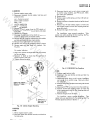
.M
w
w
w
B
c
H
el
he
yW
D
m
o
.c
se
or
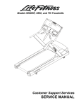
nWHEEL HORSE
1I..!l1awn & garden tractors
PRICE: $5.00
PART NO. 810063Rl
PRINTED IN U.S.A.
ona
FOREWORD
Information contained in this manual is concentrated on areas that
require adjustment, as well as removal, replacement, and overhaul of some
of the more complex systems of the tractors. Repair of major assemblies, such
as mechanical and automatic transmissions, and the Onan engine, is detailed
in other Wheel Horse Service Manuals. Repair of Briggs and Stratton or
Kohler engines, and the Peerless transaxle, is described in literature available
from their respective manufacturers.
.M
w
w
w
This publication has been prepared to assist Wheel Horse dealers in
servicing Band C-Series, 0-160 and 0-200 tractors. Information for the
C-161 Twin 8-Speed or Automatic, is given separately at the end of each
chapter.
Knowledge of basic mechanical and electrical repair work is essential
when using this publication. Always observe common shop safety rules while
performing service work.
yW
Replace all parts that are worn or no longer serviceable. Always replace
expendable parts, such as O-rings, gaskets, and seals.
Section 1 lists specifications, torque values, and special instructions
not listed in the general text. It is advised that you become familiar with this
information before making adjustments or repairs.
H
el
he
THIS MANUAL APPLIES TO THE FOLLOWING VEHICLES:
VEHICLE IDENTIFICATION NUMBER
B·81
4·Speed
82·08BP01, 92·08BP01
B·111 4-Speed
82·11 BP01, 92-11 BP01
8·Sp~ed
81-08K801,91·08K801
C-101 8·Speed
81-1 OK801, 91-1 OK801
C·121 8-Speed
81·12K801, 91-12K801
C·121 Automatic
81-12KS01
C·141 8-Speed
81·14K801,91-14K801
C·141 Automatic
81-14KS01
C·161 8-Speed
81-16K801
C-161 Automatic
81·16KS01
C·161 Twin 8-Speed
81-16B801, 91-16B801
C-161 Twin Automatic
81·16BS01,91·16BS01
0-160 Automatic
81-160S01
0-200 Automatic
81-20KS01, 91·20KS01
C·81
m
co
.
se
or
MODEL
w
w
TABLE OF CONTENTS
.M
w
SECTION 1 ....; SPECIFICATIONS AND GENERAL INFORMATION
SECTION 2 - PRE-DELIVERY SERVICE
yW
SECTION 3 - GENERAL MAINTENANCE
SECTION 4 - ENGINE
H
el
he
SECTION 5 - CLUTCH, BRAKES, TRANSMISSION/TRANSAXLE
SECTION 6 - ELECTRICAL SYSTEM
SECTION 7 - ATTACHMENT LIFTS
SECTION 9 - POWER TAKE-OFF (PTO)
m
co
.
se
or
SECTION 8 - CHASSIS
- - - _._-------------------
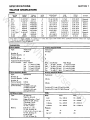
SPECIFICATIONS
SECTION 1
TRACTOR SPECIFICATIONS:
ENGINE:
ENGINE
MODel'
ENGINE
SPEC. NO.
8-81
B-111
C-81
C-I01
C-121
C-141
C-161
C-161 Twin
0-160
0-200
B-191707
B-252707
K181S
K241AS
K301AS
K321AS
K341AS
8-401407
O-BF
K532S
1136-01
0151-01
PF30700D
PF46766D
PF47648D
PF60322D
PF71246A
0130-01
MS3268F
53105A
.M
w
w
w
TRACTOR
MODel
8
11
8
10
12
14
16
16
16
19.9
=
*letter Prefix: B
Briggs & Stratton, K = Kohler, 0
I. D. plate are required to completely identify engine.
'"Engine manufacturer's rating at 3600 RPM.
, B-Series Mode's
:
Type:
:
Number of
Forward Speeds: 3
Number of
Reverse Speeds:
1
Approximate Ground Speeds
(at full throttle):
Gear Speed
1st
1.7 mph
2nd
3.6 mph
5.5 mph
3rd
2.5 mph
Rev.
!
IGNITION
19.44/318.56
24.36/399.19
18.6/304.8
23.9/391.6
29.07/476.4
31.27/512.4
35.89/588.1
40/655.7
40.3/660.4
53.68/879.7
3/76.2
3.438/87.3
2.94/74.7
3.25/82.6
3.38/85.7
3.5/88.9
3.75/95.3
3.438/87.3
3.125/79.4
3.38/85.7
2.75/69.9
2.625/66.7
2.75/69.8
2.88/72.9
3.25/82.6
3.25/82.6
3.25/82.6
2.156/54.8
2.625/66.7
3/76.2
Magneto
Magneto
Battery
Battery
Battery
Battery
Battery
Magneto
Battery
Battery
C-Series 8-Speed Models
Mechanical
All Gear
Mechanical
All Gear
6
2
(2.7 kph)
(5.8 kph)
(8.8 kph)
(4 kph)
Gear
lst
2nd
3rd
Rev.
low Range
.5 mph ( .8 kph)
.8 mph (1.3 kph)
1.4 mph (2.2 kph)
.6 mph ( 1 kph)
kph)
kph)
kph)
kph)
D-Series Automatic Models
Hydrostatic
Infinite
Infinite
se
Variable 0-7.5 mph (12 kph) Farward
Variable 0-3.6 mph (5.8 kph) Reverse
TIRES:
Sizes:
Front
o
.c
Rear
B-81
13 x 5:00-6
18 x 8:50-8
B-111
13 x 6:50-6
18 x 9:50-8
C-Series
16 x 6:50-8
23 x 8:50-12
D-Series
18 x 8:50-8
26 x 12 :00- 12
12
12
.85
.85
m
ELECTRICAL SYSTEM:
Type:
12 Volt D.C.,
Negative Ground
Alternator:
Briggs & Stratton - Dual
Circuit, 12 Volt, 3 Amp.
(Charging Circuit)
Onan and Kohler 12 Volt, 15 Amp.
Battery:
B-81, B- 111, C-81 12 Volt, 24 Amp. Hr.
C-101,C-121,C-141,C-16112 Volt, 32 Amp. Hr.
0-160, D-200
12 Volt, 45 Amp. Hr.
High Range
2 mph (3.2
3.2 mph (5.2
5.5 mph (8.8
2.6 mph (4.2
or
C-Series Automatic Models
Type:
Hydrostatic
Number of
Forward Speeds: Infinite
Number of
Reverse Speeds:
Infinite
Approximate Ground Speeds
I
(at full throttle):
Variable 0-6.3 mph
(10 kph) Forward
,
Variable 0-3.2 mph
(5.2 kph) Reverse
H
el
:
STROKE
in.!mm
he
,
BORE
in./mm
Onan. Basic engine model number shown; specification and serial numbers from engine
yW
TRANSMISSION:
DISPLACEMENT
cu. in.! cc
RATED
H.P.**
Pressure:
PSI
kg/cm 2
1-1
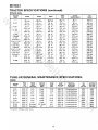
SECTION 1
TRACTOR SPECIFICATIONS (continued):
PHYSICAL DATA:
TRACTOR
MODEL
B-81
C-81
w
w
B-lll
C-l0l
LENGTH
WIDTH
37 in.
(94 em)
37 in.
(94 em)
41 in.
(104 em)
41 in.
(104 em)
41 in.
(104 em)
41 in.
(104 em)
41 in.
(104 em)
41 in.
(104 em)
41 in.
(104 em)
41 in.
(104 em)
45.5 in.
(116 em)
45.5 in.
(116 em)
65 in.
(165 em)
65 in.
(165 em)
65 in.
(165 em)
65 in.
(165 em)
65 in.
(165 em)
65 in.
(165 em)
65 in.
(165 em)
69 in.
(175.3 em)
65 in.
(165 em)
69 in.
(175.3 em)
75.5 in.
(192 em)
75.5 in.
(192 em)
34.5 in.
(88 em)
36 in.
(92 em)
36 in.
(92 em)
36 in.
(92 em)
36 in.
(92 em)
36 in.
(92 em)
36 in.
(92 em)
36 in.
(92 em)
36 in.
(92 em)
36 in.
(92 em)
45 in.
(114 em)
45 in.
(114 em)
.M
w
HEIGHT
45.5 in.
(116 em)
45.5 in.
(116 em)
45.5 in.
(116 em)
45.5 in.
(116 em)
45.5 in.
(116 em)
45.5 in.
(116 em)
45.5 in.
(116 em)
45.5 in.
(116 em)
45.5 in.
(116 em)
45.5 in.
(116 em)
50 in.
(127 em)
50 in.
(127 em)
OUTSIDE
TURNING RADIUS
.
-
80 in.
(203 em)
80 in.
(203 em)
75.75 in.
(192 em)
75.75 in.
(192 em)
75.75 in.
(192 em)
75.75 in.
(192 em)
75.75 in.
(192 em)
75.75 in.
(192 em)
75.75 in.
(192 em)
75.75 in.
(192 em)
90 in.
(229 em)
90 in.
(229 em)
DRY
WEIGHT
4001bs.
(180 kg)
4051bs.
(182 kg)
5401bs.
(243 kg)
5901bs.
(266 kg)
6001bs.
(270 kg)
6301bs.
(284 kg)
6001bs.
(270 kg)
5501bs.
(249 kg)
6401bs.
(288 kg)
5901bs.
(266 kg)
8751bs.
(394 kg)
10251bs.
(461 kg)
H
el
he
0-200
yW
C-121
8-Speed
C-121
Automatic
C-141, C-161
8-Speed
C-161 Twin
8-Speed
C-141, C- 161
Automatic
C-161 Twin
Automatic
0-160
WHEEL
BASE
TUNE-UP/GENERAL MAINTENANCE SPECIFICATIONS:
. ENGINE:
.020/.5
.020/.5
.020/.5
.020/.5
.020/.5
.020/.5
.020/.5
.020/.5
.023/.6
.020/.5
N/A
N/A
N/A
N/A
N/A
N/A
N/A
N/A
Flywheel
Flywheel
Fixed
Fixed
Fixed
Fixed
Fixed
Fixed
Fixed
Fixed
25° (Cold)
27°
SPARK
PLUG
TYPE*
CJ-8
CJ-8
J-8
H-l0
H-l0
H-l0
H-10
J-8
H-8
H-l0
i
, 'Or equivalent (Champion number shown).
1-2
SPARK
PLUG GAP
in.lmm
DIRECTION
OF ROTATION
(Facing PTO)
.030/.76
.030/.76
.025/.64
.025/.64
.025/.64
.025/.64
.025/.64
.030/.8
.025/.64
.035/.9
Counterclockwise
Counterclockwise
Counterclockwise
Counterclockwise
Cou ntercloekwise
Counterclockwise
Counterclockwise
Counterclockwise
Counterclockwise
Cou ntercloekwise
IDLE
RPM
(No Load)
1750
1750
1900
2100
2100
2100
2100
1450
1350
1350
GOVERNED
MAX. RPM
(No Load)
3300
3300
3500
3400
3400
3400
3400
3300
3600
3600
m
B-81
B-lll
C-81
C-l0l
C-121
C-141
C-161
C-161 Twin
0-160
0-200
IGNITION
TIMING
(BTDC)
o
.c
TIMING
MARK
LOCATION
se
POINT
GAP
in.lmm
or
TRACTOR
MODEL
SECTION 1
TUNE-UP/GENERAL MAINTENANCE SPECIFICATIONS
(continued):
LIQUID CAPACITIES:
qt. (1.1 I)
qt. (1.4 I)
qt. (1.2 I)
qt. (1.4 l)
qt. (1.4l)
qt. (1.4/)
qt. (1.4 I)
1% qt. (1.7 l)
qt. (2.1 I) wI filter
qt. (3.31) w/filter
.M
w
w
w
Crankcase:
B-81
1Ys
B-111
131
C-81
1 y.;
C-101
131
C-121
131
C-141 131
C-161 131
C-161 Twin 0-160 2Y.;
0-200 331
Fuel Tank:
B-Series - 131 ga I. (5.7 l)
C-Series - 3 gal. (11 .41)
0-160- 5% gal. (21.9l)
0-200 - 8 gal. (30.4 I)
he
yW
Transmission:
B-Series - % qt. (.7 l) SAE 90, API Service GL5
C-Series 8-Speed - 2 qt. (1.9 l) SAE 140, API Service GL5
C-Series Automatic - 5.5 qt. (5.2l) SAE 10W-30 or 10W-40
O-Series - 6 qt. (5.7 I) SAE 10W-30 or 10W-40
ENGINE OIL: TEMPERATURE - VISCOSITY CHART
•
Oil Viscosity
SAE 30*, 10W-30, 10W-40
SAE 5W-20 or 5W-30*, lOW, 10W-30
SAE 10W or 10W-30, Diluted 10% with kerosene
or USE" oil
Kohler Engine
SAE 30*, lOW-3D, 10W-40
SAE 10*, 5W-30, 10W-30, 10W-40
SAE 5W-20, or 5W-30
or liSE" oil
m
o
.c
Onan Engine
Above 30°F (·1 0 C)
SAE 30
Below 30°F (-1°C)
SAE 5W-30
API Service: liSE" oil
" Preferred viscosity. Use alternates listed if preferred
viscosity is unavailable.
se
·
Above 300 F (-1°C)
30° to OOF (_1° to -lSoC)
Below OOF (-18°C)
API Service: "SC" (MM), "SO" (MS)
or
H
·
Briggs and Stratton Engine
Above 40°F (40C)
40° to OOF (4° to -18°C)
Below OOF (-18°C)
API Service: "SC" (MM), "SO" (MS)
el
Air Temperature
CHASSIS:
Ir-----------~~---------------------------------------------------------~---------------------------_,I
i Zerk Fittings:
PTO Brake Adjustment (PTO engaged):
Front Wheel End Play:
B.Series 6
C-Series - 6
B-Series - .010 (.25 mm) Gap
between brake pad and pulley
0-200 .012 (.3 mm) Gap
between brake pad and pulley
O-Series - 7
C-Series .012 (.3 mm) Gap
between brake pad and pulley
0-160 - .010/.015 (.25 .4 mm)
Gap between rotor and armature
1-3
All Models 0 to .015 in. (.4 mm)
Front Wheel Alignment (toe-in):
O-Series only - 1/16· l/S in.
0.6 - 3.2 mm)
•
SECTION 1
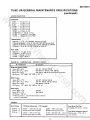
TORQUE VALUES:
SPECIAL
w
w
Tractor Model
Torque
ft-Ib
Nm
Location
28 - 32
5-8
5-8
Rear wheel hub set screws
Fuel tank front bolt
Fuel tank insert bolt
C-Series
.M
w
Fuel tank nuts
D-Series
39 -45
7 - 11.2
7 - 11.2
17
12
O-Series Models
GENERAL
8
17 - 22
30 - 35
25- 30
75 - 80
-
11
24 31
42 49
35 42
105 - 112
he
1/4 - 20
5/16-18
3/8 - 16
3/8 - 24
1/2 - 13
yW
Size
-
Torque
Nm
ft-Ib
Self Tapping Screws - All Models
15
25
21
35
el
5/16 - 18
3/8 - 16
-
Fasten rectifier wire to inside edge of frame with wire
clip
Align front wheels for 1/16 to 1/8 inch 0.6 to 3.2 mm)
toe-in
Steering gear to contain 1/4Ib.(0.1 kg) grease
Adjust choKe and throttle friction to provide 8 to 10 lb.
(1.8 to 2.3N) pull force at knobs
Adjust friction on control cam to provide 16 to 20 lb.
(3.6 to 4.5N) pull force at top of motion control lever
Tie wrap wiring harness to steering column
Grease input shaft spline of hydro pump and brake rod
(approximately 2 inches past threaded end) with "moly"
grease.
locate bottom edge of muffler 1 3/4 inch (4.4 em)
above grille shroud assembly
Adjust brake rods so brake band just clears drum with
pedal released
Adjust park brake rod with brake handle in engaged
position
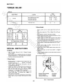
Install spring disc washers on choke and throttle controls
as shown in Fig. 1-1.
-
-
All Models
-
om
.c
se
Lube all grease fittings with No. 2 General Purpose
lithium grease
Coat exposed areas of axle hubs with anti-rust lubricant
(Texaco Compound"l, " Light, Code 1976 or equivalent)
- Install seat spring long leg toward seat.
or
H
SPECIAL INSTRUCTIONS
C-Series Models
Adjust lift chain so length from bolt through lower link
to trunnion center is 7.4 inches (19 cm). For final adjustment, see Section 7
Kohler engines: assemble engine PTO pulley 1/16 inch
(1.6 mm) from engine face
Adjust PTO brake to provide .ol2'l3 mm) clearance between brake pad and pulley when clutch is engaged
- Coat lift lever shaft with anti-rust lubricant (Texaco
Compound"L," Light, Code 1976 or equivalent)
- Use Isomount No. 106434, color code white, for all
models except C-81. Use Isomount No. 106441, no
color code, for C-St models
Fuel hose must remain clear of Sundstrand Transmission.
Secure hose to top of transaxle and bottom of hoodstand.
SPRING DISC WASHER
ONEON CHOKE
TWO ON THROTTLE
1-4
FRICTION
WASHER
(100305)
Fig. 1-1 Control Friction
SECTION 1
0·200 cable tie headlight wire and ignition wire to the
governor vacuum hose
-
-
0-200 PTO - adjust PTO clutch hook to 1 13/16
inch (4.6 em) from engine face to hook centerline. Adjust clutch turnbuckle for 16 to 18 lb. (3.6 to 4.0 N).
pull on clutch handle, and complete disengagement of
clutch pulley
-
0-200 - grease chrome bearing surface of PTO clutch
plate with "moly" grease.
w
w
PTO Brake Adjustment:
a. 0·160 - adjust PTO brake for .010/.015 inch (.25 to
.4 mm) gap between rotor and armature assembly
b. 0-200 - adjust PTO brake for .012 inch (.3 mm) gap
between brake pad and pulley with PTO engaged
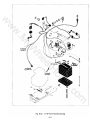
- Flex Coupling
a. 0-160 - install engine/pump flex coupling parts as
shown in Fig. 1-2
106641 SPLINE WASHER
.M
w
103029 DRIVEN COUPLING
920008 WASHER (4) REQUI RED
C-161 TWIN
TORQUE VALUES:
Same as C-Series
yW
SPECIAL INSTRUCTIONS:
Same as C-Series except:
-
Drive pulley set screw to be tightened
while PTO is engaged to pre-load thrust
bearing.
920082 LOCKWASHER
908023 BOLT
106645 MOUNTING PLATE
Fig. 1·2 0·160 Flex Coupling
se
or
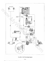
b. 0·200 - install engine/pump flex coupling parts as
shown in Fig. 1·3
H
el
he
ENGINE
MOUNTING
FACE
106641 SPLINE WASHER
103029 DRIVEN COUPLING
920008 WASHER (4) REQUIRED
m
o
.c
ENGINE
MOUNTING
FACE
102622 COUPLING
920082 LOCKWASHER
908023 BOLT
106645 MOUNTING PLATE
Fig. 1·3 0-200 Flex Coupling
1-5
SECTION 1
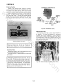
VEHICLE IDENTIFICATION NUMBER (VIN) EXPLANATION
81 20 RG 01 00001
.....- - - - - -...- - JULIAN DATE
w
w
'I
T··
:
SERIAL NUMBER
00001 through 99999
I
7
8
9
o
ENGINE MAKE CODE
B
BRIGGS & STRATTON
K
KOHLER
o = ONAN
R
RENAULT
T
TECUMSEH
E
BATTERY POWER
I
m
o
.c
'*
PRODUCT CATEGORY 7
8M
BLADE, MID MOUNT
TE
TILLER (BATTERY)
TL
TILLER
PL
MOLDBOARD PLOW
PR
PLOW, REVERSIBLE
DS
DISC
HR
HARROW
PT
PLANTER
CM
CULTIVATOR, MID MOUNT
CR
CULTIVATOR, REAR MOUNT
WG
WAGON,4·WHEEL
DC
DUMP CART
RL
ROLLER
AR
AERATOR
SW
SWEEPER
VC
LAWN VACUUM
se
PRODUCT CATEGORY 7
08
8" FURROW WIDTH
12
12" FURROW WIDTH
05
5 CU. FT. CAPACITY
10
10 CU. FT. CAPACITY
18
18 CU. FT. CAPACITY
31
31"WIDTH
38
38" WIDTH
40" WIDTH
40
42
42" WIDTH
44
44" WIDTH
50
50" WI DTH
59
59" WIDTH
ETC.
PRODUCT CATEGORY 6
ST
SNOW THROWER
BA
SNOW BLADE
BC = SNOW BLADE
BN = SNOW BLADE
or
PRODUCT CATEGORY 6
42
42" WIDTH
48
48" WIDTH
56
56" WIDTH
59
59" WIDTH
TRANSMISSION MAKE CODE
E
EATON
F
FOOTE
G
GUTBROD
P
PEERLESS
S
SUNDSTRAND
4
4·SPEED WHEEL HORSE
8
8·SPEED WHEEL HORSE
PRODUCT CATEGORY 5
MS
MID MOUNT, SIDE DISCHARGE
MR
MID MOUNT, REAR DISCHARGE
RS
REAR MOUNT, SIDE DISCHARGE
RR
REAR MOUNT, REAR DISCHARGE
FS
FRONT MOUNT, SIDE DISCHARGE
FR
FRONT MOUNT, REAR DISCHARGE
H
PRODUCT CATEGORY 5
26
26" CUT WI DTH
30
30" CUT WI DTH
32
32" CUT WIDTH
36
36" CUT WIDTH
42" CUT WI DTH
42
48
48" CUT WIDTH
60" CUT WIDTH
. 60
YEAR
7'" 1977
8 = 1978
PRODUCT CATEGORIES 1, 2, 3, 4
EFFECTIVE CATEGORY MEASUREMENT
IE - HORSEPOWER, WIDTH OR CAPACITY FOR:
PRODUCT CATEGORIES 1, 2, 3, 4
05
5 H.P.
08
8 H.P.
10
10 H.P.
11
11 H.P.
12
12 H.P.
14
14 H.P.
16
16 H.P.
20
20 H.P.
365th day
of year
BASIC PRODUCT INFORMATION FOR:
el
he
6
Loo,
I
PARTS LIST CODE
01 through 99
yW
5
i
I
1
.M
w
MODEL YEAR
6 = 1976
7
1977
8
1978
9
1979
o 1980
1
1981
2
1982
3
1983
4
1984
-~
:ye;r~n::aymanUfactured
IN CERTAIN CASES, THIS MA Y BE CODED WITH AN "X", ny", OR "Z" IN EITHER POSITION. THIS IS TO A VOID DUPLICATION OF V.I.N. NUMBERS WHERE BASIC PRODUCT INFORMATION IS IDENTICAL. EXAMPLE: 85-36MR01 AND 85·36XR01.
1-6
II
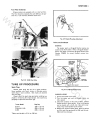
PRE-DELIVERY SERVICE
SECTION 2
B-SERIES, C-SERIES, and D-SERIES Automatic Tractors
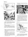
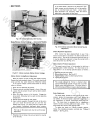
Install Front Wheel and Tire Assemblies
Using a suitable hoist or jack, raise the front of the
tractor.
w
w
A. If a floor jack is used, center the jack under the frame
assembly behind the front axle. Use a 2" x 4" piece of
lumber or similar material, long enough to span the
width of the frame, between the jack and the tractor
to prevent damage to the vehicle.
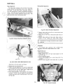
B. If a chain hoist is used, attach the hoist to the front
axle, being careful not to scratch the side of the engine,
hood, or the axle itself. On C and D-Series tractors, an
alternate hoisting point can be made by installing a
piece of rod stock (5/8" on C-Series; 3/4" on D-Series)
in the front Tach-a-matic hitch. Be careful not to
scratch the grille.
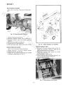
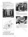
t050"(ThiCk) Shim Washer
@ ...3'h-16x~BOlt
.M
w
@
\ ~ C8~ Hub Cap
1
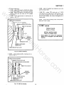
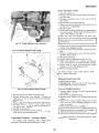
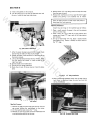
Install a wheel and tire assembly on each spindle as
illustrated in Fig. 2-1, 2-2, or 2-3, as appropriate. The
tire valve stem should be to the outside on B-Series vehicles
! and
to the inside on C and D-Series vehicles. Correct
wheel end play is 0 to .015 inch (.4 mm). In some cases it
may be necessary to add or remove a shim washer to
, achieve correct end play.
%" o. D. Washer
Fig. 2-3 D-Series Front Wheel Installation
yW
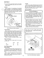
Install Footrest (D-Series Only)
el
he
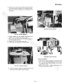
Raise the rear of the tractor (see Install Rear Wheel and
Tire Assemblies). Install the footrests as shown in Fig. 2-4.
Note that the bolt holding the rear of the mid lift bearing
must be removed to install the footrest and is replaced after
the footrest is installed. The "L" shaped bracket is installed at the front of each footrest as shown in Fig. 2-4 .
.015 "(Thin) Shim Washer
~~ .050"(Thick) Shim Washer
@1!lI~ O~ Snap Ring
CS'foaHUbCap
13t ·O.D. Washer
S
se
Fig. 2-1 B-Series Front Wheel Installation
or
H
\
o
.c
Footrest
6::'\~Bracket
~Bolts
~.050"(ThiCk) Shim Washer
\
m
1!lI~~Snap Ring
C@~UbCap
1'12t " O. D. Washer
Fig. 2-4 D-Series Footrest Installation
Install Rear Wheel and Tire Assemblies
Fig. 2·2 C-Series Front Wheel Installation
2-'
Raise the rear of the tractor.
A. If a floor jack is used, center the jack under the transmission case_ Use a 2" x 4" block of wood or similar
material, between the jack and the transmission to prevent damage to the transmission case.
SECTION 2
D-SERIES
B. If a chain hoist is used, attach the hoist to the drawbar
hitch on C and D-Series tractors and to the rear axle on
B-Series tractors.
With the front wheels straight ahead, place the steering
wheel on the steering shaft so that the spokes form a "Y".
Secure the wheel with a 5/8-18 jam nut. Snap the steering
wheel insert into place so the "R", inside the wheel, is
straight when viewed from the driver's seat.
• B-SERIES
w
Apply a coating of rust preventative on the axle shafts
(Texaco Compound "L," Light, Code 1976, or equivalent).
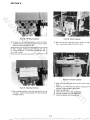
Mount a rear wheel and tire on each axle shaft as shown in
Fig. 2-5, with the tire valve stem to the outside. Use the
shim washers as required for minimum end play. Lower the
tractor, and remove the jack or hoist.
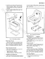
Service the Battery
.&CAUTION&
w
Electrolyte and battery fluid are poisonous and can
be injurious to eyes, skin, and clothing. In the event
of an accident, flush immediately with a solution of
one part bakin\l soda to four parts water. Notify
physician immediately. If baking soda is not immediately available, flush affected area with water. Notify physician immediately.
.M
w
.015 "(Thin)
.050"(Thick}
'~
j
Shim Washers (As Req.'d)
\0~
H
el
he
yW
1. Remove the battery from the tractor.
Never fill
battery with electrolyte with battery installed in tractor.
2. Use an electrolyte with a specific gravity of 1.260; fill
each cell until the electrolyte (battery acid) is 1/4 to 1/2
inch (6 to 13 mm) over the top of the separators. DO
NOT OVERFI LL.
3. Place the filled dry charged battery on charge before installing. Charge at 15 amperes for 30 minutes. After
charging, top off each cell with electrolyte.
Fig. 2-5 B-Series Rear Wheel Installation
C AND D-SERI ES
After battery has been in service, add only low
mineral content water. DO NOT ADD E LECTROLYTE (battery acid).
or
Mount a rear wheel and tire assembly on each axle hub
so the tire valve stem faces inside on the C-Series and outside on the D-Series. Secure each wheel and tire assembly
with the lug bolts provided. On C-Series tractors, starting
at the top, tighten every other lug bolt until all are tight.
On D-Series tractors, alternately tighten lug bolts on
opposite sides of the wheel until all are tight. Torque the
lug bolts to 75 to 80 ft. Ibs. {105 to 112 Nml.
Lower the tractor and remove the jack or hoist.
.
se
Adjust Tire Pressure
Using a low pressure tire gauge, adjust the tire pressure
in all four tires:
Rear
PSI
12
12
kg/cm 2
.85
.85
m
co
Front
Mount Steering Wheel
~
BAND C-SERI ES
Install the bowed spring washer and plastic spacer over
the steering shaft. With the wheels straight ahead, install
steering wheel so that the spokes form a "Y" and line up
the hole in the wheel hub with the hole in the steering
shaft.
Insert a 1/4 punch through the hole to hold the steering
wheel in position. Install the 1/4 x 2 spirol pin by
driving it in with a hammer; as the spirol pin is driven in, it
should push the punch out.
REAR, (-SERIES
FRONT, B-SERIES
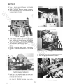
Fig. 2-6 Band C-Series Battery Installation
2-2
SECTION
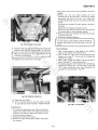
of seat pivot plate on D-Series tractors. Remove the hardware and re-attach seat springs to top side of seat pivott
plate. See Fig. 2-8.
w
w
4. Install battery in the tractor, making sure the terminal
posts are positioned properly. Install the battery
hold down assembly. Tighten the nuts only enough
to keep the battery from moving. DO NOT OVERTIGHTEN.
5. Reinstall the battery cables as shown in Fig. 2-6 and
Fig. 2-7. Grease all exposed metal surfaces of the
battery terminals.
.M
w
,
REAR
I
~
)
H
el
he
yW
Fig. 2-8 D-Series Seat Installation
Fig. 2-7 O-Series Battery Installation
or
Check Wiring and Attaching Hardware
.
se
Visually inspect for any loose connections and tighten as required. Check routing of wires to make sure
they will not be disturbed by any moving part that
could cause a short.
Check that nuts, bolts, and other fasteners are in
place and tight.
Check Engine Oil Level
Check that the engine oil is at the proper level and
for oil leaks. Engines are filled with SAE 30 oil at the
factory. If the tractor is to be operated in cold temperatures, it may be necessary to change the oil. Refer to the
Engine Oil Temperature-Viscosity Chart in Section 1.
Fill the Fuel Tank
Lubricate Tractor
m
co
Use a good grade of regular or unleaded gasoline (90
octane or higher). Open the fuel shut-off valve and
check fuel hose and fittings for leaks.
Check Transmission Oil Level
!
2~
Grease all lube points as shown in the maintenance
section of the tractor Owner's Manual (front axle, both
front wheel spindles, both front wheels, and steering
gear; on D-Series tractors, also grease the steering gear
bell crank). Use No. 2 mUlti-purpose lithium grease.
Check that the transmission oil is at the proper level
an'd for oil leaks. Oil specifications are:
4-Speed Transmission - SAE 90
8-Speed Transmission - SAE 140
Automatic Transmission - SAE 1OW-30 to 10W-40
Test Tractor Operation
Install Seat (C and D-Series Only)
A. As applicable, check or test operation of the following:
Mount seat to seat springs with lockwashers and bolts on
C-Series models. The seat springs are secured to the bottom
1. Engine, choke, and throttle controls
2. Gauges
2-3
!
SECTION 2
w
3.
4.
5.
6.
7.
8.
9.
10.
Lights
PTO clutch and brake
Lift system
Service and parking brakes
Transmission clutch
Transmission controls
Steering
Tractor operation in all speeds forward and reverse
Check Front Wheel Alignment (D-Series Only)
With the tractor's wheels straight ahead, there should
be a small amount (1/16 to 1/8 inch/l.5 to 3 mm) of
"toe·in" adjustment.
If required, adjust the steering as described in Section
8.
B. Test operation of the safety interlock system. The
engine should NOT start if:
1. a) The clutch pedal is not depressed on manual
transmission models.
b) The brake/return to neutral pedal is not depressed on automatic transmission models.
2. The PTO lever or switch is in the Engaged or On
position.
. On models so equipped, also check the operation of
the seat switch. With the engine running and the PTO
engaged, rise off the tractor's seat - the engine should
shut off.
C. On automatic transmission models, check that the
transmission neutral adjustment is properly set. Operate the tractor under full throttle and allow it to
thoroughly warm up. Bring the tractor to a stop
using the brake/return to neutral pedal. Release the
pedal; if the tractor "creeps" in either direction, set
the neutral adjustment as described in Section 5.
w
Install Drawbar Hitch Pin (C and D-Series Only)
.M
w
Install the drawbar hitch pin in the drawbar hitch
and secure with a hairpin cotter.
Install Mower Belt Adjustment Bolt (B-Series Only)
Thread the 3/& 16 nut onto the 3/8-16 x 2 full
thread bolt; thread the bolt into the front side of the
mower hanger bracket, located just behind the front axle.
Tighten the nut against the bracket to secure.
yW
C-161 TWIN
Follow procedure for C-Series.
H
el
he
NOTES
---~-.~
or
~
---~-~--.--
--_
...
- - - - -.....
~---
..
m
co
.
se
- - - - - - - .. --•..
.....
--------
- - - _....._ . _ - - - - -
- - - - _... - -
----...
....
- - _.....- - - - _......
2-4
- - - - - - - - - - - - - _ .....
_ __. - -_ _
..
.....
........
_
..
---~
------
GENERAL MAINTENANCE
MAINTENANCE CHECKLIST
co
=.
0
;;
III
a
n
III
III
-:.: '".
-<
'":.:0
~
<
=
III
~
".
<
0
:.:
!i
w
..s;: . ..!i .
".
ENGINE OIL
,. .. .. ..
=- -< -< -<
III
C
0
co
0
<
0
c
~
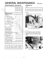
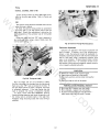
SECTION 3
Oil Level
III
<
co
-...'"
Never overfill the engine crankcase with oil. The oil
level must not exceed the "F" level on the dipstick.
0
0
:.:
0
c
w
~
B-SERIES
SERVICE OPERATION
The oil level should be to the top of the oil fill tube.
.M
w
Check:
Engine Oil Level
X
Battery Water Level
X
Automatic
Transmission
O i l Level
X
X
Manual
X
Tire Pressures
yW
Tightness of all
Attaching Hardware
Clean Engine Cooling Fins
X
X
Clean Air Filter
B-Series
X
X
C & O-Series
Change Engine Oil (11
Replace Engine Oil
Filter (O-Series) ( 11
Inspect Spark Plugs
Replace Spark Plug(s)
X
el
he
Lubricate Chassis
X
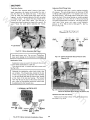
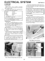
Fig. 3-1 B-Series Oil Fill and Drain Plugs
X
X
C-SERIES
X
100 Hours
H
Inspect Breaker Points
On engines with oil filler tubes, remove the dipstick by twisting the cap sl ightly and pulling. Engines
without oil filler tubes have a combination filler plug
and dipstick located on the right side of the engine
block.
100 Hours/ One Year(21
Replace Transmission Oil
Filter (Automatic) (1)
100 Hours/ One Year(21
Replace Fuel Filter (O-Series)
100 Hours/ One Year (2)
Clean and Lubricate
PTO Clutch (0-200)
100 Hours/ One Year(2 )
se
100 Hours/ One Year(2 1
or
Replace Air Filter
Change Transm ission Oil
(Automatic)
(1 ) Refer to te x t for initial service interval for new tractors .
o
.c
(2) Whichever occurs /irst.
m
These service intervals are considered MAXI MUM
under normal operating conditions.
I ncrease frequency under extremely dirty or dusty conditions.
Fig. 3-2 C-Series Filler Plug Dipstick
,.
3-1
SECTION 3
D-SERIES
Be sure to add the same viscosity oil as is presently in the
engine. New tractors are shipped with SAE 30 oil in the
crankcase. It may be necessary to change the original oil
before using the tractor if the tractor will be operated in
cold weather.
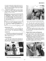
Remove the 0-160 dipstick by twisting the cap
slightly and pulling. The 0-200 dipstick is removed
by turning the cap counterclockwise and then pulling.
w
Oil Changes
.M
w
w
Failure to change the engine oil (and oil filter on 0Series models) at recommended intervals can lead to
serious damage to the engine. This is especially true
when using detergent oils which are designed to hold
impurities in suspension; when the saturation point
is reached, the oil may suddenly break down to form
a gelatin-like substance which seriously impairs and
can even stop the flow of oil. Increase the frequency of oil and oil filter changes if the tractor is
operated under extremely dusty conditions.
-..,d~tl.;tti_----
OIL DRAIN
PLUG
yW
Before changing the oil, start the engine and allow it to
warm up. This will allow the oil to flow more freely. Shut
off the engine and remove the key.
After adding the prescribed amount of oil, check the oil
level. Add oil as necessary to bring the oil to the "Full"
level in B-Series engines or into the "Safe" range on the
dipstick in C and D-Series engines.
Fig. 3-3 0-160 Oil Dipstick and Drain Plug
el
he
engi~e
Oil'~he
NEVER overfill the
crankcase with
oil level must not exceed the "F" level on the dipstick.
Oil Filter (0-160, 0-200)
H
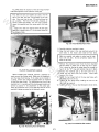
The engine in 0-160 and 0-200 tractors is equipped with
a full flow oil filter. The filter should be replaced along
with the engine oil after the first 2 hours of operation.
Thereafter, the filter should be replaced at 50 operating
hour intervals (every second oil change), or sooner if the
tractor is operated under extremely dusty conditions.
or
Fig. 3-4 Oil Dipstick and Drain Plug
FULL
MARK
on FILl
Iil
m
o
.c
se
DO NOT
EXCEED
Fig. 3-5 Correct Oil Level - C and D-Series
Fig. 3-6 Right Side Engine Baffle Removed, 0-200
3-2
SECTION:
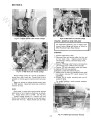
To prevent any dirt or other contaminants from
entering the engine, always cover the carbu retor air
horn when the air cleaner is removed.
w
B-SERIES
.M
w
w
To service the air filter, remove the two screws air
lift off the complete air cleaner assembly. Remove tit
screen and spacers from the foam element and remo\l
the element from the body of the air cleaner.
8-81
Fig. 3-7 Engine Oil Filter, 0-160
yW
8-111
el
he
Fig. 3-9 B-Series Air Cleaners
Wash the foam element in a solution of liquid detel
gent and water. Wrap the foam in a clean cloth am
squeeze dry. Saturate the element in clean engine 0)
(same viscosity as is presently being used in the engine
and squeeze to remove excess oil.
When assembling, make certain the lip of the foarr
element extends over the edge of the air cleaner bod"
Fig. 3-8 Remove Oil Filter, O-Series
H
C-SERIES ANO 0-200
or
The dry type air filter element installed on C-Serie
and 0-200 engines is cleaned by tapping it lightly on
flat surface to remove loose dirt particles. Replace thl
element if dirt does not drop off easily. DO NOT was;
elements in any liquid or attempt to blow dirt off witt
compressed air as this will puncture the filter elemen·
.
se
Hand tigbten oil filter only; turn filter until the
the
engine block,
rubber
gasket
contacts
then tighten an additional 1/4 to 1/2 turn. Excessive
tightening or use of a wrench or other mechanical
device can cause damage to both the filter and the
engine.
Air Filter
m
co
Clean the engine air filter on B-Series tractors after
every 25 hours of operation, and after every 50 hours of
operation on C and O-Series tractors (more often if the
tractor is operated under extremely dusty conditions).
Replace dry type filter elements at 100 hour intervals,
or once a year, whichever comes first. The foam type elements used on B-Series vehicles may be serviceableformore
than 100 hours or one year of operation, provided the element shows no sign of deterioration and can still be cleaned
satisfactorily.. Replacement intervals must be shortened
when operating under extremely dusty conditions. To protect the engine, use only the manufacturer's replacement
filter, or replacement filters with equivalent specifications.
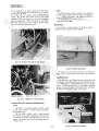
Fig. 3-10 C-Series and 0-200 Air Cleaner
3-3
~------
-------------
SECTION 3
Check the following when installing a new or serviced
element:
w
w
1. Back plate must be securely tightened to carburetor.
Replace back plate if bent or cracked.
2. Gasket surfaces of element must be flat against back
plate cover to seal effectively.
3. Wing nut must be finger tight
DO NOT OVERTIGHTEN.
The 0-200 and some C-Series engines are equipped
with a precleaner slipped over the dry element, which
traps much of the dirt and prevents it from entering the
dry element. Servicing of the precleaner is accomplish·
, ed by washing it in soap and water, rinsing, then squeez·
ing out the excess water and allowing it to dry. DO
NOT 01 L THE PRECLEANER.
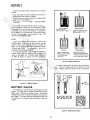
FULLY CHARGED
.M
w
Acid in water gives electrolyte
specific gravity of 1.260.
GOING DOWN
As battery discharges, acid
begins to lodge in plates.
Specific gravity drops.
0-160
yW
A dry type element with precleaner is used on the
0·160's engine. Cleaning of the filter element, plus the
checks to make when installing a new or serviced element, are the same as described in this section under
"C-Series and 0-200." The precleaner is serviced as
described in the following paragraph.
To clean the precleaner, wash in water and detergent,
remove excess water by squeezing like a sponge and
allow to thoroughly dry. Distribute three tablespoons
of SAE 30 engine oil evenly around the precleaner.
3
Battery half discharged.
More acid in plates, less in
electrolyte. Starting
failure likely.
he
1
2
DISCHARGED
END/LIFE
Acid almost entirely in
plates, leaving weak electro·
Iyte behind. Specific gravity
lower, almost that of water.
Fig. 3-12 Battery Chemistry
W.,SH
SQI,lEEZE DAY
CO"',. WITH 011..
el
se
or
H
In reading a hydrometer, the barrel must be held vertically. Draw just enough acid into the barrel to lift the
float. The float should not touch any part of the barrel.
Fig. 3-11 0-160 Air Cleaner
BATTERY CHECK
EYE
LEVEL
o
.c
A hydrometer is used to measure specific gravity of the
battery. The water level in the battery should be at normal
height when a hydrometer reading is taken. Hydrometer
readings should never be taken immediately after water has
been added. The water should be thoroughly mixed with
the electrolyte, by charging, before hydrometer values are
reliable.
High floet Ileft) means high
specific gravity. Low float
means low specific gravity.
m
Correct method of
reading hydrometer.
Eye on lavel with
liquid surface. Disregard
curvature
of liquid against
glass parts. Do not
tilt
hydrometer
while
reading.
Keep float vertical.
Fig. 3-13 Reading Hydrometer
3-4
SECTION
~
Fuel Filter (O-Series)
D-Series tractors are equipped with an in-line fuel filter.
This fi Iter should be replaced after each 100 hours of operation or at 1 year intervals, whichever occurs first.
.M
w
w
w
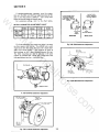
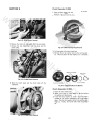
Fig. 3-16 Spark Plug Gap Adjustment
Points and Condenser
he
yW
B-SERIES
Fig. 3-14 D-160 Fuel Filter
The breaker points on Briggs & Stratton engines ara
located under the flywheel. Refer to Briggs & Strattor
Service and Repair Instructions (Briggs & Stratton Parl1
Number 270962) for correct flywheel removal pro.
cedures.
el
se
or
H
Fig. 3-15 0-200 Fuel Filter
TUNE UP PROCEDURE
Spark Plugs
Replace spark plugs that are not in good condition.
Never sandblast, wire brush, scrape, or otherwise service
spark plugs in poor condition. Best results are obtained
with new plugs.
Always check the spark plug gap before installing new
plug(s) or reinstalling the original plug(s}. Use a spark plug
gap gauge to adjust the electrode air gap.
B-Series
C-Series & D-160
D-200
.030 in. 1.8 mm}
.025 in. (.6 mm)
.035 in. (.9 mm)
C-SERI ES & 0-200
om
Plug Gap
.c
Tractor Model
Fig. 3-17 B-Series Breaker Points
1. Remove the breaker point cover.
2. Turn the engine over until the breaker points are!
fully opened.
3. Check the condition of the point surfaces. Always;
replace burned or pitted points. Dirty or oily points;
can be cleaned with a cloth, but make sure no par-·
ticles of lif)t remain between point surfaces .
4. Measure the gap with a feeler gauge. When the points;
are fully open, the gap should be .020 inch (.5 mm) ..
Adjust points as necessary.
Tighten spark plug(s} to 22 ft. Ibs. (30 Nm).
3-5
SECTION 3
6. Remove the air intake hose that connects to the
blower housing. This provides an access to viewing
the timing mark.
w
w
w
Fig. 3-18 C·Series Breaker Points
.M
yW
Fig. 3·20 0·160 Breaker Point Gap
el
he
7. Check the ignition timing by connecting a continuity
light across the ignition breaker points. Connect one
lead from the light to the negative side of the ignition
coil (terminal that leads into the breaker box to the
breaker points). Ground the other lead of the light to
a good ground on the engine.
8. Turn the engine crankshaft counterclockwise until
the points close. The light should now be on.
9. Slowly turn the crankshaft clockwise. Adjust the
point gap so the lamp goes out as the timing mark on
the flywheel aligns with the 25 0 BTC (before top
center) mark.
Fig. 3-19 0·200 Breaker Point Adjustment
0-160
co
e.
The points are located on the top of the front side of
the engine inside a breaker box.
To check the breaker points, with a cold engine, remove the two nuts holding the heat baffle to the top of
the engine and remove the heat baffle. Use the following
procedure to check and adjust breaker points gap.
s
or
H
Under normal operating conditions, a certain amount
of buildup or metal transfer between the point surfaces
will occur. If this occurs too frequently and becomes
excessive, the condenser may be at fault.
REMOVE HOSE AND VIEW
TIMING MARKS THROUGH
THIS HOLE
1. Remove the two screws and the breaker box cap.
2. Remove the two spark plugs so the engine can be
turned by hand. Check the condition of the spark
plugs at this time.
3. Turn the engine over until the breaker points are
fully opened.
4. Check the condition of the breaker point surfaces.
Always replace burned, or pitted points. Dirty or oily
points can be cleaned with a cloth, but make sure no
particles of lint remain between point surfaces.
5. If point replacement is necessary, replace the breaker
points with a new set. Adjust point gap to an initial
setting of .023 inch (.6 mm).
CORRECT TIMING 25 0
BTC COLD SETTING
m
Fig.3·21 0·160 Timing Mark
Under normal operating conditions, a certain amount
or buildup or metal transfer between the point surfaces
will occur. Ilf this occurs too frequently and becomes
excessive, the condenser may be at fault.
3·6
SECTION ::
Timing
B-SERIES, C-SERIES, AND 0-160
Ignition timing on the B, C, and D-160 models is controlled by the point gap setting. Refer to Points and
Condenser.
The ignition timing should be checked each time the
breaker point gap is altered.
To check the ignition timing connect an automotive
type timing light to the high tension lead of the left
spark plug. Consult the manufacturer's instruction for
exact connections of the particular type of timing light
used.
Rotate the engine until the "SP" mark is observed in
the timing sight hole; using a piece of chalk, mark the
line for easier reading.
.M
w
w
w
0-200
Fig. 3-23 Governor Flange Mounting Screws
yW
Carburetor Adjustment
el
he
Carburetors are adjusted in the factory and should nott
have to be reset. If however, one of the following conditions is noted, the carburetor should be readjusted immediately as continued operation with incorrect setting cam
lead to fouled spark plugs, overheating, excessive valve
wear, or other problems. If black exhaust smoke is noted"
check the air cleaner first - an "overrich" mixture is usually caused by a poorly serviced, clogged air cleaner element"
not an improperly adjusted carburetor.
or
POSSIBLE CAUSE/PROBABLE REMEDY
A. Mixture too rich - readjust main fuel needle.
B. Mixture too lean - readjust main fuel needle.
C. Idle speed too low or improper idle adjustment readjust speed, then idle fuel needle if needed.
m
co
.
se
Start the engine and run at 1/2 throttle or above.
Aim the timing light into the sight hole; the light should
flash just as the "SP" mark is centered in the hole. If
the light flashes before the mark is centered, the timing
is excessively advanced. If the light flashes after the
mark is centered, the timing is excessively retarded.
To adjust, loosen (DO NOT REMOVE) governor
flange mounting capscrews and rotate the governor until
the timing mark is centered exactly in the sight hole.
Retighten flange mounting screws after exact timing is
achieved.
A. Black, sooty exhaust smoke, engine sluggish.
B. Engine m isses and backfires at high speed.
C. Engine starts, sputters, and dies under cold weather
starting.
D. Engine runs rough or stalls at idle speed.
H
Fig. 3-22 Timing the 0-200
CONDITION
3-7
SECTION 3
If readjustment becomes necessary, stop the engine,
then turn the MAIN and IDLE fuel adjusting screws all the
way in until they bottom LIGHTLY - don't force them
closed, as this will damage the needle valves.
For preliminary settings, refer to the chart below.
MAIN FUEL
(HIGH SPEED)
ADJUSTMENT
w
w
INITIAL CARBURETOR AOJUSTMENT CHART
B-Series
C-Series
0-160
0-200
2
turns
1 1/8
turns
2
turns
1 1/4
turns
1/2· 1
turns
1 1/4
turns
Main Fuel 1 1/8
Valve
turns
.M
w
Idle Valve 1 1/8
turns
THROTTLE
STOP
SCREW
SIDE VIEW
For final adjustments, start engine and allow it to warm
up, then operate at full throttle. Turn MAIN fuel in until
engine slows down (lean side). then out until it slows down
again from overrich setting - note positions of screw at
both settings, then set it about halfway between the two.
The IDLE fuel setting can then be adjusted in the same
manner for smoothest idle. Rough idle is often due to the
idle speed being set too low - check this also.
IDLE
ADJUSTMENT
REAR VIEW
Fig. 3-26 0-160 Carburetor Adjustment
NEEDLE VALVE
MAIN FUEL
ADJUSTMENT
(2 TURNS OPEN)
Fig. 3-27 0-200 Carburetor Adjustment
se
or
H
el
he
yW
IDLE VALVE
Fig. 3-24 B-Series Carburetor Adjustment
m
o
.c
IDLE FUEL ADJUSTMENT
1-1/4 TURNS OPEN--
Fig. 3-25 C-Series Carburetor Adjustment
3-8
C-161 TWIN
ENGINE OIL -
Same as C-Series.
AIR FILTER Same as C-Series except:
saturate the precleaner in engine oil and
squeeze to remove excess oil.
w
w
Fig. 3-30
.M
w
FINAL ADJUSTMENT
1.
Place governor speed control lever in
"IDLE" position. Hold throttle lever
against idle stop and set idle speed adjusting screw to obtain 1450 R.P.M.
Turn idle valve slowly clockwise (lean
mixture) until engine misses or R.P.M.
slows. Then turn idle valve ~ turn
counterclockwise.
2.
Hold throttle shaft in closed position
and adJust idle speed screw to 900
R.P.M. Release the throttle. With remote
control in idle position, adjust tab" A"
to obtain to 1450 R.P.M. See Fig. 3-31.
-PRE-CLEANER
C-161 Twin Air Filter
yW
Fig.3-28
BATTERY CHECK 3-4.
As described on page
TUNE-UP PROCEDURE
Spark Plugs -
C-161 Twin Carburetor
Adjustment
Same as B-Series.
he
ADJUSTMENT
n(~~~~~~-l~~~S~C~RE~
WIRES ON
TERMINAL
CONNECTION
Fig. 3-29
C-161 Twin Governor Idle Spring
NOTE: Governed idle must be adjusted
on all engines for proper operation. The
smaller spring keeps the engine on
governor, even at idle speed. If moderate
loads are applied at idle, the engine will
not stall. Idle speed should be no lower
than 1100 R.P.M.
LOCK NUT
C-161 Twin Breaker Points
Same as C-Series.
Turn
CARBURETOR ADJUSTMENT
needle valve clockwise until it just closes.
VALVE MAY BE DAMAGED BY TURNING
IT IN TOO FAR. Now open needle valve 1 ~
turns counterclockwise. Close idle valve in
same manner and open 1 ~ turns. This initial
adjustment will permit the engine to be
started and warmed up prior to final adjustment. See Fig. 3-30.
3.
o
.c
TIMING -
Fig. 3-31
BENDING
TOOL
se
MOUNTING SCREW
or
H
POINT GAP .020"
el
Points and Condenser- The breaker points
on Briggs & Stratton engines are located behind the flywheel. Refer to Briggs & Stratton
"Twin
Cylinder
Service
Instructions"
(Briggs & Stratton Part Number 271172) for
correct service procedures.
m
Place governor speed control lever in
fast position. Then turn needle valve in
slowly clockwise (lean) until engine
misses or R.P.M. slows. Then turn
needle valve ~ turn counterclockwise.
If engine does not accelerate properly,
readjust needle valve approximately Va
turn counterclockwise (richer).
3-9
ENGINE
SECTION 4
CHOKE AND THROTTLE CONTROL ROUTING
AND ADJUSTMENT
B-SERIES
.M
w
w
w
Choke cable is located on left side of dash panel and
parallels gas line to carburetor. See Fig. 4-1. Adjust
choke by loosening cable retainer clamp at carburetor
end. Set choke handle in full COLD position. Then
tighten retainer clamp to hold choke butterfly in fully
closed position.
Throttle cable is located on right side of dash panel
leading from control handle to governor. See Fig. 4·1.
Adjust throttle by loosening cable retainer clamp at
engine. Set throttle handle to full OPERATE position.
Tighten retainer clamp to hold throttle in fully open
position.
Fig. 4-2 C-S1 Choke Linkage
el
he
yW
Fig.4-1 B-Series Choke and Throttle Linkage
Fig. 4-3 C-S1 Throttle Linkage
C-SERI ES (Except C-S1)
Throttle cable is located on right side of dash panel.
It passes through a cable clip on right side of engine into
throttle control bracket. See Fig. 4·4. To adjust, place
throttle in full OPERATE position. Loosen throttle
setscrew and rotate throttle control bracket clockwise to
stop position. Tighten throttle cable setscrew.
C-S1 (Only)
Throttle cable is located on right side of dash panel,
leading under engine into a retainer clamp. End of
throttle wire inserts into first hole above stop pin. See
Fig. 4-3. Adjust throttle by loosening cable retainer
clamp. Set throttle handle to full OPERATE position.
Tighten retainer clamp with throttle in fully open position and stop pin against bracket.
D-SERIES
0-160
o
.c
se
Choke cable is located on left side of dash panel. It
passes around bottom of engine through two cable clips
and into a retainer clamp at carburetor. Adjust choke by
loosening cable retainer clamp at carburetor. Set handle
in full COLD position and tighten retainer clamp to
hold choke butterfly in fully closed position. See Fig.
4-2.
or
H
C-SERIES
m
Choke cable is routed from control handle, around
battery, through retainer clip on engine to choke lever
on carburetor. Adjust choke with choke handle in the
COLD-START position. Loosen cable clamp on engine.
Tighten cable clamp to hold choke butterfly in closed
position. See Fig. 4-5.
4-1
SECTION 4
.M
w
w
w
Fig. 4-4 C-Series (Except C-S1) Throttle Linkage
Fig. 4·6 0-200 Choke and Throttle Linkage
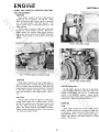
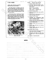
ENGINE - REMOVE AND REPLACE
yW
For engine repair operations, refer to engine manu·
facturer literature (Briggs and Stratton or Kohler! or
Wheel Horse Onan Engine Repair Manual.
B-SERIES
Fig. 4-5 0-160 Choke and Throttle Linkage
or
For engine installation, reverse removal procedure.
See Fig. 4-7.
.
se
Throttle linkage consists of a control rod attached to
throttle lever with a cotter pin. Forward end of rod is
attached to throttle governor bellcrank with ball swivel
bolt.
Adjust the throttle by placing throttle control lever
in FAST position. Adjust ball swivel stud so bellcrank
contacts rear stop.
H
el
he
1. Remove negative battery cable.
2. Disconnect choke and throttle cables, fuel line, and
all four electric lines:
magneto ground (green),
alternator/lights (yellow), alternator/charge (red),
starter (black).
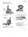
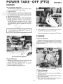
3. Separate PTO linkage under frame by removing clevis
pin and hairpin cotter at PTO clutch turnbuckle.
4. Remove PTO brake adjustment screw and bracket.
5. Remove PTO clutch cone assembly.
6. Remove crankshaft bolt and bearing race.
7. Relieve drive belt tension by depressing clutch pedal
and remove remaining PTO clutch housing from
crankshaft.
8. Remove four (4) engine mounting bolts and lift
engine off frame.
0-200
m
co
Choke cable is routed from control handle through
cable clamp on top of engine to choke lever on carburetor.
Adjust choke same as 0-160. See Fig. 4-6.
Throttle linkage consists of a control rod from
throttle lever attached to governor control bell crank at
second hole from top. Adjust throttle same as 0-160.
4-2
Fig. 4-7 B-Series Engine and Clutch Removal
SECTION 41
C-SERIES
3. Disconnect electric wires to coil, starter, orange wire
to rectifier plug, headlights, and PTO clutch. Mark
wire colors for replacement.
4. Remove grille.
5. Remove upper muffler clamps, and four (4) bolts on
grille shroud.
6. Remove mufflers and complete hood and grille shroud
assembly.
7. Remove four (4) bolts holding engine to frame and
slide engine forward until the flex coupling slides off
pump drive shaft.
S. Remove the engine from the frame.
1. Remove negative battery cable.
2. Disconnect choke and throttle cables, fuel lines, and
all electric lines:
w
w
red - 2 wires to solenoid
battery cable to solenoid
black - coil
rectifier regulator plug
orange - rectifier plug
Remove the belt guard.
Remove the hairpin cotter from the PTO clutch rn0.
Remove the PTO shaft clevis pin, and pivot yoke away
from shaft.
Remove the PTO brake.
Disengage the transmission drive clutch on automatic
models or depress clutch on S-speed models.
Remove drive belt from the transmission drive pulley
and slide belt forward to clear engine pulley.
Remove through bolts from front isomounts.
Remove nuts securing rear isomount block to frame.
Remove engine with rear block still attached. See
Fig. 4-S.
.M
w
3.
4.
5.
6.
7.
S.
yW
9.
10.
11.
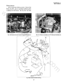
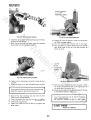
For installation, reverse removal procedure. Take
special note when assembling the flex coupling. See Fig.
4-9 and special instructions in Section 1.
a
For engine installation:
he
1. Align front isomount through bolt with front block,
but do not tighten.
2. Maneuver rear block so studs drop through holes in
frame and secure with nuts.
3. Tighten all mounting bolts.
o
" KI
o
H
el
Fig. 4-9 0-160/0-200 Flex Coupling
0-200
o
.c
se
or
1. Remove negative battery cable.
2. Disconnect choke and throttle controls and fuel line
from fuel pump.
3. Disconnect electric wires to coil, starter, headlights,
and orange wire to rectifier plug. Mark wire colors
for replacement.
4: Remove mufflers and complete hood and grille shroud
assembly.
5. Disconnect the PTO rod trunnion from the clutch bar.
6. Remove four (4) bolts holding engine to frame and
slide engine forward until the flex coupling slides off
pump drive shaft.
7. Remove the engine from the frame.
m
For installation, reverse removal procedure. Take
special note when assembling the flex coupling. See Fig.
4-9 and special instructions in Section 1
Fig. 4-8 C-Series Engine Mounting
O-SERIES
0-160
1. Remove negative battery cable.
2. Disconnect choke and throttle controls, and fuel line
from fuel pump.
4-3
ENGINE -
C-161 TWIN
CHOKE AND THROTTLE CONTROL
ROUTING AND ADJUSTMENT
1.
Remove negative battery cable.
2.
Disconnect choke and throttle cables,
fuel lines, hood stop cable, and all
electric lines:
battery cable to solenoid
black magneto ground
red &. yellow - alternator plug
w
w
w
The choke control is located on the left
side of the dash panel. The choke cable runs
over the top of the engine and connects to
the rear of the carburetor. Set the handle in
the RUN position and tighten the retaining
clamp to hold the choke butteryfly in the
full open position.
.M
The throttle control is located on the right
side of the dash panel. The throttle cable
runs over the top of the engine and connects
to the governor linkage at the top of the
engine. Set the throttle to the full OPERATE
position and tighten the clamp to hold the
throttle in the fully open position.
he
yW
3.
Remove the belt guard.
4.
Remove the hairpin cotter from the PTO
clutch rod.
5.
Remove the PTO shaft clevis pin, and
pivot yoke away from shaft.
6.
Remove the PTO brake.
7.
Disengage the transmission drive
clutch on automatic models or depr6'Ss
clutch on 8-speed models.
8.
Remove drive belt from the transmission drive pulley and slide belt forward
to clear engine pulley.
9.
Remove through bolts from front isomounts.
10.
Remove nuts securing rear isomount
block to frame.
11.
Remove engine with rear block still
attached. See Fig. 4-8.
FOR ENGINE INSTALLATION:
1.
el
2.
C-161 Twin Choke and
Throttle Controls
Align front isomount through bolt with
front block, but do not tighten.
Maneuver rear block so studs drop
through holes in frame and secure with
nuts.
H
Fig. 4-10
REMOVE AND REPLACE
3.
Tighten all mounting bolts.
---,-~---
s
or
NOTES
m
co
e.
4-4
CLUTCH, BRAKES,
TRANSM ISSION/TRANSAXLE
SECTION 5 ,
w
8. Cut old belt or remove by working belt through geall
shift access hole.
9. Feed half the new belt through gearshift access hole aft
end and half around the gearshift lever through thl
access hole forward end.
10. Place forward end of belt over engine drive pu Iley, and re:
place pulley onto engine shaft and secure with bolt am
race.
11. Place aft end of belt over transmission pulley.
12. Route belt around idler pulleys.
13. Replace belt guides and retaining nuts.
14. Release the clutch, check belt alignment, and set beh
guides as shown in Fig. 5-1.
15. Replace PTO cone and linkage, and adjust PTO brake!
See Section 9.
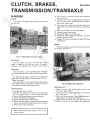
Transmission is disengaged from the engine by clutching
the drive belt.
.M
w
w
yW
Brakes
The B-Series employs a positive action disc type brake on
the transaxle. See Fig. 5-2.
he
Fig. 5-1 B-Series Belt Routing and Linkage
Idler Pulleys
se
Both idler pulleys use wire type belt guides. The guides
can rotate around the pulleys and must be correctly adjusted.
To adjust the belt guides, loosen the nuts holding the
guides and move the guides to positions shown in Fig. 5-1.
Tighten nuts securely.
Two belt guides are used to capture belt at engine pUlley.
These guides should be adjusted to 1/16 inch (1.5 mm)
from drive belt with the clutch pedal released.
or
H
Belt Guides
el
Two idler pulleys are used on the drive belt. A flat
pulley is located on the idler lever, and a V pulley is
stationary. No adjustment can be made to either pulley.
Fig. 5-2 B-Series Brake Adjustment
Brake Adjustment
Belt Replacement
o
.c
1. Depress the foot brake and set parking brake in the
first notch. See Fig. 5-3.
2. Loosen lock nut and tighten adjusting nut on brake cam
lever. See Fig. 5-2.
3. Push or pull tractor by hand. Proper brake adjustment is
achieved when rear wheels skid across floor.
4. Release brakes and check that brake disc turns freely.
5. Tighten the lock nut and recheck brake adjustment.
m
1. Place gear shift lever in neutral.
2. Separate PTO linkage under frame by removing clevis
pin and hairpin cotter at PTO clutch turnbuckle.
3. Remove PTO brake adjustment screw and bracket.
4. Remove PTO clutch cone assembly.
5. Remove crankshaft bolt and bearing race.
6. Relieve drive belt tension by depressing clutch pedal and
remove remaining PTO clutch housing from crankshaft.
7. Remove idler pulley belt guides.
When removing belt guides, pulleys are free if nuts
are not replaced.
5-1
i SECTION 5
.M
w
w
w
FI RST
IOTCH
Fig. 5-3 B-Series Parking Brake lever
Clutch Rod Adjustment - a-Speed Models
The 8-speed clutch rod adjustment is made to adjust
clutch pedal position. To reposition pedal, adjust the
position of the threaded trunnion on the clutch rod, at the
left rear of the vehicle. See Fig. 5-6. The adjustment is
more easily made by disconnecting the clutch rod at the
clutch pedal.
Belt Guide Adjustment - a-Speed Models
yW
, Transaxle
Fig. 5-5 C-Series a-Speed Belt Routing
For complete repair operations, refer to manufacturer's service manual for Peerless Model 669.
H
el
he
Belt guide tangs are located on the belt guard top and
bottom front edge. To adjust, bend the guides with the
belt under tension.
Belt Replacement - a·Speed Models
Remove belt guard and right side foot rest.
loosen clutch idler pulley.
Depress clutch and slip belt off rear drive pulley.
Remove PTO rod trunnion.
Remove yoke clevis pin and pull yoke aside.
Remove PTO brake.
Remove old belt and reverse procedure for new belt
installation. Adjust PTO brake. See Section 9.
or
1.
2.
3.
4.
5.
6.
7.
Brake - 8-Speed Models
Fig. 5-4 B-Series Transaxle
.
se
The brake band, located on the left side of the transmission, brakes the transmission, and, in turn, brakes the
rear wheels. See Fig. 5-6.
Remove and Replace Transaxle
1.
2.
3.
4.
5.
m
co
lift tractor to rei ieve weight from transax Ie.
Place gearshift lever in neutral.
Depress clutch and slip drive belt off transaxle pulley.
Disconnect brake lever and return spring at brake.
Remove 3 bolts from transaxle support bracket. Fig.
5-4.
, 6. Remove 6 bolts from axle support brackets at frame .
. 7. Raise tractor frame and remove transaxle while guiding
gearshift lever through access hole and the belt.
Reverse above procedure for replacement.
C-SERIES
Clutch - 8-Speed Models
Transmission is disengaged from the engine by clutching
the drive belt, located on the right side of vehicle. See Fig.
5-5.
BRAJKIE
5-2
~ ----------------------------------------
ADJ IJISiMIENT
Fig. 5-6 C-Series a-Speed Clutch Pedal and Brake Adjustments;
SECTION 5
Brake Adjustment - S-Speed Models
w
1. Depress the brake pedal and engage parking brake.
2. With the parking brake engaged, adjust the nut on the
end of the rod until the brake band is tight enough to
skid both rear wheels when the tractor is pushed.
3. Tighten the nut another 1/2 turn.
w
When properly adjusted, the parking brake lever should
not travel to the end of the slot when parking brake is engaged.
Transmission - a-Speed Models
.M
w
For complete repair operations, refer to Wheel Horse
Mechanical Transmission Repair Manual No. A-1392.
Fig. 5-S C-Series S-Speed Seat Pan Supports
el
he
yW
Fig. 5-7 C-Series S-Speed Transmission
H
Remove and Replace Transmission -
S-Speed Models
1. Drain the transmission oil.
2. Remove gearshift and park brake knobs and shift cover
plate.
3. Depress clutch pedal and slip belt off drive pulley.
4. Remove seat hinge brackets and seat.
5. Unbolt seat pan and disconnect seat switch wires and
tail light wires if applicable.
6. Remove seat pan.
7. Remove two (2) bolts holding seat pan support bracket
to top of transmission. Remove fuel line and conduit
clamps, close fuel valve, and disconnect fuel line at
tank.
Fig. 5-9 C-Series S-Speed Transmission Removed
or
To replace transmission, reverse above precedure. Refill
with oil.
.
se
Clutch - Automatic Models
Transmission is disengaged from engine by clutching the
drive belt located on the right side of vehicle. See Fig. 5-10.
Belt Guide Adjustment
Secure fuel line to steering wheel to prevent fuel line
from draining.
Belt Replacement
Same procedure as 8-Speed, except that idler pulley
need not be loosened.
8. Remove two (2) bolts and nuts holding seat pan support
bracket (not the fuel tank forward bolts).
9. Lift off fuel tank along with both brackets, and set tank
aside.
10. Drive spirol pin from range selector lever.
11. Remove clutch return spring from transmission casting.
12. Disconnect rear brake rod at bellcrank.
13. Support frame of tractor and remove four (4) bolts
holding transmission to frame. See Fig. 5-9.
14. Disconnect range lever as transmission is pulled away
~m~~
m
co
Same procedure as 8-Speed.
~
I SECTION 5
If the brake band is severely out of adjustment (too
tight), proper neutral adjustment will not be possible
due to restricted brake pedal travel. Loosen brake
band adjustment nut completely, make the neutral
adjustment, then adjust the brake band.
.M
w
w
w
Fig. 5-10 C-Series Automatic, Belt Routing
Brake/Motion Control Linkage - Automatic Models
yW
Fig. 5-12 C-Series Automatic, Motion Control Neutral
Adjustment
Detent Alignment Adjustment
el
he
After neutral has been adjusted, check to see if the
motion control lever is centered in the detent notch of the
detent spring. The spring incorporates slotted bolt holes so
it may be adjusted as required to line up the neutral notch
with the control rod. See Fig. 5-11.
Motion Control Friction Adjustment
Fig. 5-11 C-Series Automatic, Motion Control Linkage
H
The speed control lever is friction-loaded to hold any
selected speed in either direction. If the lever does not remain where it is set during operation, adjust as follows:
Motion Control Linkage Neutral Adjustment
se
Place the tractor on a level surface with engine running.
Depress the brake pedal and release. The tractor should not
creep and the rear wheels should be effectively locked.
If the tractor creeps on a level surface while in neutral.
adjust as follows:
The proper amount of friction is obtained when
approximately 61bs. (1.4 N) of force at the top of the
handle moves the control lever. The friction collar is
self-lubricating and does not require added lubrication.
Brake Adjustment
o
.c
1. Block the rear wheels oft the ground.
2. Remove controls cover plate located in front of the seat.
3. Loosen the set screws in the arm with an allen wrench.
See Fig. 5-12.
4. Start the engine and run at full throttle. Engage the
drive clutch. Allow drive train to reach normal operating
temperature.
5. Depress the brake pedal fully and release.
6. Insert a short screwdriver through the hole in the nylon
cam and rotate the eccentric cam pin until the rear
wheels stop turning. This usually occurs at a point midway between forward and backward wheel rotation.
m
The brake band, located on the left side of the transmission, brakes the transmission and, in turn, brakes the
rear wheels. As the brake pedal is depressed, linkage returns
the transmission to neutral, dynamically braking the tractor. The brake band is actuated after the transmission
reaches neutral, providing additional braking action. The
brake band also serves as the parking brake.
To adjust the brake on C-Series automatic tractors,
follow the preceding procedure outlined under "S-Speed
Models." See Fig. 5-13.
The lobe on the eccentric pin must be up for proper
adjustment.
7. Retighten the set screw in the arm and retest for neutral
at full throttle.
Remove controls cover plate.
Release large locknut. See Fig. 5-11.
Tighten friction collar to desired spring friction.
Tighten large locknut.
or
1.
2.
3.
4.
5-4
SECTION 5
Remove and Replace Transaxle
w
w
1. Drain the transaxle oil.
2. Remove knob from drive clutch handle and remove control cover plate.
3. Disengage transmission drive clutch and slip belt off
drive pulley.
4. Remove seat hinge brackets and seat.
5. Unbolt seat pan and disconnect seat switch wires and
tail light wires (if applicable).
6. Remove seat pan.
7. Remove two (2) bolts holding seat pan support bracket
to top of transaxle. Remove fuel line clamp and conduit
clamp (Ref. 8-Speed, Fig. ~8).
8. Close fuel valve and disconnect gas line at tank.
.M
w
<
Jel
Secure fuel line to steering wheel to prevent f : :line
from draining.
Fig. 5-13 C-Series Automatic Brake Adjustment
~--------------.
yW
,
Remove and Replace Motion Control Linkage
----
el
he
9. Remove two (2) bolts and nuts holding seat pan support
bracket (Ref. 8-Speed, Fig. ~8).
10. Lift off fuel tank along with both brackets and set tank
aside.
11. Remove nut holding pin to rear of motion control lever
assembly. See Fig. ~14.
12. Remove left side panel.
13. Remove brake rod adjusting nut. (Ref. Fig. ~13).
14. Models with hydraulic lift: disconnect two hydraulic
lines at pump and mark for replacement (Ref. Fig. ~8).
15. Support frame of tractor and remove 4 bolts holding
transaxle to frame (Ref. 8-Speed, Fig. ~9).
16. Remove transaxle assembly.
To replace transaxle, reverse above procedure.
with oil. Adjust brake band.
Refill
or
H
Remove and Replace Input Pulley
1. Remove right rear wheel.
2. Disengage drive clutch and slip belt off drive pulley.
3. Remove hex bolt on shaft and pull pulley.
Fig. 5-14 C-Series Motion Control linkage
Remove and Replace Pump/Motor
om
.c
se
1. Complete steps 1 through 12 under Transaxle Remove
and Replace.
2. Remove left rear wheel for clearance.
3. Complete steps 13 and 14 under Transaxle Remove and
Replace.
4. Remove two transaxle case bolts holding top of drive
motor and two lower bolts holdi ng bottom of drive
motor to transaxle.
5. Remove pump and motor as an assembly.
1. Remove controls cover plate and left side cover.
2. Remove parking brake lever assembly. Remove nut
holding pin to rear of motion control lever assembly.
See Fig. ~14.
3. Remove bolt from motion control shaft retaining tab.
4. Release pressure on motion control tension spring.
5. Pull shaft out far enough to expose woodruff key on
left side of shaft. Remove key.
6. Pull shaft all the way out.
7. Carefully remove motion control handle assembly from
under gas line and electrical harness.
Whenever pump/motor are removed from transaxle,
always clean strainer and replace oil filter.
To replace pump/motor, reverse above procedure. Refill
with oil. Adjust brake band.
Transmission/Transaxle - Automatic Models
For complete repair operations, refer to Wheel Horse
Automatic Transmission Repair Manual No. A-1391.
~5
SECTION 5
Implement Relief/Charge Valve
Push Valve Function
The implement relief valve is used to regulate hydraulic
lift pressure. This valve limits pressure to maximum of 550
to 700 psi (38 to 50 kg/cm 2 ). It is located to the rear of
the pump housing. The charge pressure relief valve is located to the front of the pump housing on models equipped
with a hydraulic lift, and to the rear of the pump housing
on models equipped with a manual lift. The charge pressure
relief valve limits pump and motor circuit hydraulic
pressure to 70 to 150 psi (4.9 to 10.5 kg/cm 2 ). See Fig.
5-17 and Fig. 5-18.
w
w
Because of the "dynamic brake" feature of the hydrostatic transmission, the tractor can be pushed for only a
few feet before the rear wheels will lock. If the tractor
must be pushed, the manual bypass Push Valve must be
opened. The valve is located inboard of the left rear wheel
on C-Series tractors. To operate the valve, follow the instructions on the "push valve" decal. The valve has a
! square head and can be opened or closed with a wrench. Be
: sure to close the valve before operating the tractor.
.M
w
IPLUG
J
II
yW
U Gl'Il
~NO
Fig. 5-15 C-Series Automatic, Push Valve
he
Hand push tractor only. Do not tow. Towing can
cause severe damage to the hydrostatic transmission.
Acceleration Valves
Fig. 5-17 C-Series Automatic Charge Pressure Valve
(Manual Lift)
el
Acceleration valves are used in the hydraulic drive circuit
to limit vehicle acceleration to a safe rate.
Two valves are used: a forward valve and a reverse valve.
See Fig. 5-16.
om
.c
se
or
H
Although the acceleration valves look simi lar, they
are not alike. The forward valve, located at the rear
of the end cap housing, incorporates wider relief flats
on the valve lands than does the reverse valve, located
at the front of the end cap housing. The forward
valve may be used in place of the reverse valve; however, under no circumstance should the reverse valve
be substituted for the forward valve.
Fig. 5-18 C-Series Automatic Implement Relief/Charge
Valves and Hydraulic Hose Routing (Hydraulic liftl
Hydraulic Hose and line Routing
Hydraulic line routing is shown in Fig. 5-18. Connections
are shown in Fig. 5-19.
5
~J.tr ~ s~
8ALl
Fig. 5-16 C-Series Automatic Acceleration Valves
5-6
SECTION 5
An access hole is provided in the right console panel for
the neutral adjustment.
If the tractor creeps when in neutral, adjust as follows:
OJ.
1. Block the rear wheels off the ground.
2. Loosen the cap screw holding the eccentric assembly.
See Fig. 5-20.
3. Start the engine and run at half throttle. Allow drive
train to reach normal operating temperature.
4. Depress the brake pedal and release.
5. Rotate the eccentric until the rear wheels stop. (This
usually occurs at a point midway between forward and
backward wheel rotation.)
6. Retighten the cap screw while holding the eccentric
assembly from turning.
7. Increase engine speed to full throttle.
8. Move speed control lever in both directions and return it
to neutral with the pedal. (Repeat several ti mes and readjust if necessary.)
.M
w
w
w
'" ,
Fig. 5-19 C-Series Automatic Hydraulic Hose Connections
Hydraulic Flushing Instructions
yW
If the brake band is severely out of adjustment (too
tight), proper neutral adjustment will not be possible
due to restricted brake pedal travel. Loosen brake
band adjustment nut completely, make the neutral
adjustment, then adjust the brake band.
D-SERIES
Detent Alignment Adjustment
After motion control has been adjusted for neutral, adjust the trunnion on the upper end of the control rod until
the control handle is in the neutral slot on the side panel.
See Fig. 5-21.
el
Drive Line
he
To flush foreign matter from lines, use kerosene or
equivalent solvent.
To flush hydraulic lift valve, allow solvent to flow
through it.
To flush pump and motor, it is necessary to disassemble
and overhaul.
To flush implement cylinder, blow all oil out by pushing
cylinder rod in and out. Flush with solvent.
The D-Series utilizes a flex coupling directly connecting
the engine and the hydraulic pump. Oil is directed through
a hydraulic manifold connecting the pump to a hydraulic
motor.
The motion control lever is friction-loaded to hold a
selected speed in either direction. If the lever does not remain where it is set during operation, the friction may be
increased by tightening the adjusting nut through the
access hole located in the right panel. See Fig. 5-20.
or
H
Brake/Motion Control Linkage
Motion Control Friction Adjustment
m
o
.c
se
The proper amount of friction is obtained when
approximately 16 to 20 lb. (3.6 to 4.5 N) of force at
the handle moves the control lever.
Fig. 5-20 D-Series, Friction and Neutral Adjustment
Motion Control Linkage Neutral Adjustment
Place the tractor on a level surface with engine running.
Depress the brake pedal and release. The tractor should not
creep and the rear wheels should be effectively locked.
Fig. 5-21 D-Series, Motion Control Detent Adjustment
5-7
SECTION 5
Parking Brake Adjustment
Brake Adjustment
.M
w
w
w
The brake band, located on the left side of the transmission, brakes the transmission and, in turn, brakes the
rear wheels. As the brake pedal is depressed, linkage returns the transmission to neutral, dynamically braking the
tractor. The brake band is actuated after the transmission
reaches neutral, providing additional braking action. The
brake band also serves as the parking brake.
Fig. 5-24 D-Series Park Brake Adjustment
yW
1. Depress brake pedal and pull up on park brake knob
locking it in the notch.
2. Adjust nuts on rear rod to hold brake pedal fully de·
pressed.
3. Depress brake pedal and move park brake knob to
bottom of slot, making sure brake pedal releases.
he
Fig. 5-22 D-Series, Brake Band Adjustment (front)
If adjustment is too tight, the knob rod will not latch
in the slot.
el
Transaxle
H
For complete repair operations, refer to Wheel Horse
Automatic Transmission Repair Manual No. A-1391.
Transaxle Removal
se
or
1. Drain the transaxle oil.
2. Block up the tractor wlth jack stands adjacent to the
rea r foot rest.
3. Remove both rear wheels.
4. Remove axle housing links, or dozer blade hitch if so
equipped.
5. Remove brake rod from brake band (Ref. Fig. 5-23).
Fig. 5-23 D-Series, Brake Band Adjustment (rear)
o
.c
Adjustment of the foot brake is as follows:
m
1. Release both foot and park brake.
2. Tighten the band adjustment nut until the brake band
can no longer be slid from side to side on the brake drum.
3. Back off the nut until the brake band is again free to
slide from side to side. See Fig. 5-23 .
. 4. Front brake adjustment is only required if the linkage is
removed. The jam nuts are adjusted so the spacer just
contacts the spring, and the spring remains free to turn.
See Fig. 5-22.
5-8
Fig. 5-25 Transaxle Assembly
SECTION 5
6. Remove two 1/2 inch and two 3/8 inch cap screws that
retain the hydraulic manifold to the hydrostatic motor.
7. Tie up the rear of the manifold so it is held clear of the
motor pad.
.M
w
w
w
Fig. 5-28 Lowering Transaxle
yW
Fig. 5-26 Hydraulic Manifold
se
or
H
el
he
8. Remove dipstick and tube assembly from transaxle and
install a 1/2 inch pipe plug to keep out dirt.
9. Place a floor jack under transaxle assembly to support it
for remaining bolt removal.
10. Remove four front butt plate-to·case bolts.
11. Remove four top frame plate to transaxle bolts.
Fig. 5-29 Transaxle Removed
Transaxle Installation
o
.c
1. Install new seal rings on the motor manifold mountingl
pad. The two large high pressure ports each require am
"0" ring with a square section backup ring centered om
top of each "0" ring.
2. Apply a small amount of grease in the recesses and om
the rings to hold them in place.
Fig. 5-27 Transaxle Top Bolts
m
12. Lower the transaxle. keeping it aligned between the butt
plate and the frame angles to prevent binding.
5-9
SECTION 5
.M
w
w
w
Fig. 5-30 "0" Ring Installation
Fig. 5·32 Raising Transaxle
3. To keep out dirt during installation, cover the motor
manifold mounting pad and seals with a piece of card·
board and hold with a piece of wire.
yW
5. Start the top four case bolts using a punch for align·
ment. Leave them slightly loose at this time.
After transaxle installation, cut retaining wire and
remove cardboard. Lift manifold to make sure seals
are still in place.
or
H
el
he
Fig. 5·33 Transaxle Top Bolts
se
6. Align the front case holes with the butt plate using a
punch.
7. Install the four front bolts and washers, making sure the
transaxle is squarely against both plates.
8. Tighten all eight bolts.
9. Install the axle links or hitch as applicable.
10. Connect the brake rod to the brake band.
11. Install the dipstick and tube assembly.
Fig. 5·31 Mounting Pad Cover
o
.c
4. Place transaxle squarely in the jack, and jack the unit up
into place. Prevent binding between the front plate and
the angle brackets.
m
5-10
SECTION 5
.M
w
w
w
4. Disconnect all three control rods connected to the pump
linkage.
5. Remove the four cap screws holding the front
manifold pad to the pump pad. The two rear screws
have elastic stop nuts on the top. An oil drain pan
should be placed under this area, since there will be some
oil loss.
6. Disconnect the hydraulic lift tubes located at the top of
the pump.
7. Disconnect the temperature sending unit wire.
8. Remove the two 5/16 inch bolts and nuts that hold the
rear pump bracket to the steering gear support.
9. Remove the bolt that attaches the front pump bracket
to the left side panel.
10. Remove the pump and brackets.
If a new pump is to be installed, carefully change the
brackets and linkage from the old pump to the new
pump.
Fig. 5-34 Transaxle Front Bolts
yW
12. Carefully align and lower the manifold pad in place and
install the two 3/8 inch bolts and two 1/2 inch bolts.
Pump Installation
1. Place a small amount of clean grease in the manifold
plate seal ring recesses and on the seal rings.
2. Place a small "0" ring in each of the low pressure port
recesses and a large "0" ring in each of the large high
pressu re port recesses.
3. Place a square section type backup ring over the top of
each of the large "0" rings, centering them.
4. To facilitate alignment of the pump to the manifold pad,
fabricate two aligning pins. Cut the heads off two 3/816 x 2 bolts to make two studs. Saw a screwdriver slot
and taper the ends as shown in Fig. 5--37.
Make sure the special seal ring is used under the head
of the front 1/2 inch bolt.
or
H
el
he
13. Tighten all four bolts evenly and securely.
.
se
Fig. 5-35 Manifold Installation
m
co
14. Install both rear wheels.
15. Fill the transaxle with oil, start the engine, and check
for any leaks and proper operation. Adjust brake band.
Fig. 5-36 "0" Ring Ports
Pump Removal
1. To remove the hydrostatic pump, follow instructions in
section 4 for engine removal. The engine may be moved
forward on the frame for access to the pump, or removed from the frame, as desired.
2. Disconnect and remove the battery.
3. Remove the right console panel, together with the battery supports.
5--11
SECTION 5
5. Screw the aligning pins into the two front threaded
holes in the pump pad.
6. Install the pump by placing it carefully in position.
7. Insert the aligning pins into the front manifold holes as
the pump is lowered into place.
.M
w
w
w
Fig. 5·39 Manifold Installed
yW
Fig. 5·37 Aligning Pins
Fig. 5·40 Control Rod Connections
or
H
el
he
8. Allow the pump bracket to rest on the steering gear
brace. Install punches through the side panel holes and
into the front bracket to hold the pump in position.
9. Install the two 5/16 inch bolts and nuts and secure the
rear pump bracket to the steering gear brace.
10. Secure the left panel to the front bracket with the bolt
and nut.
11. Connect the hydraulic tubes to the pump fittings.
12. Connect the temperature indicator wire to the sending
unit.
15. Connect the three control rods to their respective levers.
16. Install the right side panel and battery supports.
m
o
.c
se
Fig. 5·38 Temperature Sending Unit
13. Install the two rear manifold·to·pump cap screws from
underneath. Place the 3/8 inch elastic stop nuts on top.
but do not tighten at this ti me.
14. Remove the two aligning studs and install the two front
cap screws and tighten all four cap screws evenly.
Fig.5·41 Side Panel Installation
5·12
SECTION 5
Motor Installation
17. Lubricate the pump spline and splined washer with
"moly" grease and slide the engine carefully to the rear.
18. Engage the pump spline with the pump coupling; center
the engine on the pump shaft.
.M
w
w
w
Fig. 5-43 Motor Mounting Area
yW
Fig. 5-43 shows the motor mounting area with the intake
screen pulled out. The two cap screw holes on each side of
the screen and the two top corner holes are for the four
bolts which retain the motor to the case.
Fig. 5-42 Pump Spline Engagement
Bolt the engine securely to the frame.
Connect engine controls as required.
Install and connect the battery.
Install the grille shroud and hood.
Test the unit for proper operation.
Check the oil level, filling as required.
1. Apply a small amount of grease to the motor manifold
pad recesses and the "0" rings to hold them in place.
2. Install two small "0" rings in the two low pressure ports.
3. Install a third small "0" ring around the right front bolt
hole, located at the top left corner of the manifold pad.
4. Center a square section backup ring on top of each of
the large "0" rings and install them in the two large high
pressu re ports.
he
19.
20.
21.
22.
23.
' 24.
Motor Removal
el
If neutral and tension adjustments were moved, they
will require readjustment.
H
When properly installed, the bottom of the backup
rings will be just below the top of the recess. Be careful not to get dirt on the pad surface.
1. Jack the tractor up under the frame and remove the left
rear wheel.
2. Place an oil drain pan under the motor and transaxle to
I
(3.
I
i 8.
Remove the four cap screws that hold the manifold pad
to the motor (Ref. Fig. 5-46).
.
Tie up the manifold so it will clear the motor pad.
Disconnect brake rod from brake band.
Remove the nuts from the two bolts securing the top
section of the motor to the transaxle (Ref. Fig. 5-44) .
Remove the two lower motor-to-case cap screws which
thread into the case. (Ref. Fig. 5-43).
Remove the motor.
om
.c
se
4.
,5.
,6.
;
. 7.
catch oil as the motor is removed.
or
i
Fig. 5-44 "0" Ring Installation
5-13
SECTION 5
4. Remove these "0" rings being careful to keep dirt away
from the open oil ports.
5. Remove the manifold by turning it past the steering gear
bracket and pulling it out towards rear of tractor.
5. Install a new gasket on the transaxle.
6. line the motor up on the two top case bolts and install
the nuts. Install the two lower cap screws.
w
Cover all open oil ports in both motor and
keep loose dirt from entering.
pu~
---.-J
w
Manifold Installation
Install new seal rings on the manifold pad as follows :
yW
.M
w
1. Place a small amount of grease in the seal ring recesses
and on the seal rings.
2. Place a small "0" ring in each of the low pressure port
recesses and a large "0" ring in each of the high pressure
port recesses.
3. On top of each large "0" ring, place a square section
type backup ring. Center it exactly on top of each of
the "0" rings.
Fig. 5·45 Motor Installation
H
el
he
7. After the motor has been secured to the transaxle, check
the seal rings to make sure they are in position.
8. Release the back of the manifold if it was tied up during
the motor removal.
9. Line up the manifold and install the four (4) bolts. Make
sure the special seal washer is under the head of the
right front bolt.
10. Connect brake rod to brake band.
11. Test the unit for proper operation.
12. Check the oil level, filling as required. Adjust the brake
band.
se
or
Fig. 5-47 "0" Ring Installation
4. Place a protective cardboard cover over the seal rings to
hold them in place and keep the area free from dirt
during installation.
m
o
.c
Fig. 5-46 Manifold Installed
Manifold Removal
1. Remove two 3/8 inch allen head screws and two 1/2 inch
cap screws holding the manifold pad to the motor.
2. Lift the manifold and remove the "0" rings.
3. Remove the two cap screws and two hex head bolts and
nuts holding the manifold to the pump.
-
-- _._ - --- - - - - - --
- - -
Fig. 5·48 Protected Seal Rings
5-14
- - - - _._ -- - - - - - - -
- - ------ -
-
SECTION 5
Fig. 5-49 shows the location of the seal rings and manifold attaching bolts at the hydraulic motor pad.
.M
w
w
w
Two 3/8 inch bolts and washers are used at the left
side of the pad, and two 1/2 inch bolts at the right
side. Also note that the rear 1/2 inch bolt does not
use a washer. The front 1/2 inch bolt, however, requires a special seal washer. An "0" ring is used between the manifold and the motor pad at this location.
These extra seals are required since this bolt goes
down into a pressure area. If it is not sealed, there will
be a major oil leak.
Fig. 5-51 Rear Manifold Pad in Place
yW
5. Carefully hold the manifold in place.
6. Align the bolt holes in the rear manifold pad with the
bolt holes in the motor and install all four bolts.
Make sure special seal washer is under head of right
front 1/2 inch bolt. Do not completely tighten the
bolts at this time.
el
he
Fig. 5-49 Ring and Bolt Locations
7. Remove the protective cover from the front manifold
pad and check to make sure all seal rings are in place.
This is done by flexing the tubes down just enough to
feel if all the "0" rings and backup rings are in place.
8. Position the manifold pad so the bolt holes line up.
9. Install the two short front hex screws. Leave them
loose at this time.
10. Install the two longer bolts in the two rear holes, with
the elastic stop nuts on top.
11. Tighten all four bolts evenly, holding the nuts on the
rear bolts as required.
12. Tighten all four of the rear manifold pad-to-motor bolts.
m
o
.c
se
or
H
Before installing the manifold, examine it carefully for
cracks around the tubing welds. Make sure the clamps prevent the tubes from flexing. If the tubes can be moved in
a clamp, remove the clamps and shape them as required
to hold the tubes firmly. Fig. 5-50 shows the front of the
manifold as it is inserted past the steering gear bracket and
turned to position it for attachment to the pump pad.
Leave the protective cover on this pad while the rear of the
manifold is being connected to the hydraulic motor.
Fig. 5-52 Front Manifold Pad Installed
Fig. 5-50 Positioning Front of Manifold
5-15
SECTION 5
Push Valve Function
w
Because of the "dynamic brake" feature of the hydrostatic transmission, the tractor can be pushed for only a few
feet before the rear wheels will lock. If the tractor must be
pushed, the manual bypass Push Valve must be opened.
The valve is located on the left side of the tractor above the
footrest. To operate the valve, follow the instructions on
the "push valve" decal. The valve has a square head and
can be opened or closed with a socket wrench. Be sure to
close the valve before operating the tractor. See Fig. 5-53.
w
YfRSf:
V' Vi!
AS ~ I'JI I
yW
.M
w
, lLJG--
Fig. 5-54 Acceleration Valves
Implement Relief Valve
el
he
The implement relief valve is used to regulate hydraulic
lift pressure. This valve limits pressure to a maximum
of 550 to 700 psi (38 to 50 kg/cm 2 ). The valve is located
to the rear of the pump on the right side. See Fig. 5-55.
The charge pressure relief valve is located on the left, and
limits pump and motor circuit hydraulic pressure to 70 to
150 psi (4.9 to 10.5 kg/cm 2 ).
Fig. 5-53 D-Series Push Valve
Hand push tractor only. Do not tow. Towing can
cause severe damage to the hydrostatic transmission.
.c
se
or
Acceleration valves are used in the hydraulic drive circuit
to limit vehicle acceleration to a safe rate.
Two valves are used: a forward valve and a reverse valve.
See Fig. 5-54.
H
Acceleration Valves
Although the acceleration valves look similar, they are
not alike. The forward valve, located at the rear of
the end cap housing, incorporates wider relief flats on
the valve lands than does the reverse valve, located at
the front of the end cap housing. The forward valve
may be used in place of the reverse valve; however,
under no circumstances should the reverse valve be
substituted for the forward valve.
Fig. 5-55 D-Series Charge and Implement Relief Valves
om
5-16
SECTION 5
Hydraulic Hose and Line Routing
Fig. 5-56 D-Series Hydraulic Lines Routing
Routing of hydraulic lines is illustrated in Fig. 5-56.
Hydraulic Flushing Instructions
w
w
w
To flush foreign matter from lines, use kerosene or
equivalent solvent.
To flush hydraulic lift valve and manifold, allow solvent
to flow through it.
To flush pump and motor, it is necessary to disassemble and overhaul.
To flush implement cylinder, blow all oil out by pushing
cylinder rod in and out. Flush with solvent.
C-161 TWIN
.M
Same as C-Series
yW
Fig. 5-56 D-Series Hydraulic Lines Routing
NOTES
el
he
- - - - --- -- - -
.c
se
or
H
- - - -- - - - - - -- - - - -- - -- - - - -- - - - -- - - - - - - - - - - ----
- - - - - - - -- - - _._ - -- - - - - - -- _
._- -
- -_ .
-
5-17
-
om
- - - - - - .- .- - -- - ---- --
- -- - -- - - - - - - - - - - - -
- --
..
- - - -- - - -
ELECTRICAL SYSTEM
B-SERIES
The alternator charging system normally requires no service other than periodically checking that all exposed wiring
and electrical connections on the tractor are clean, tight,
and in good condition.
Ignition System
w
Magneto ignition is used in the B-Series. The ignition
switch is used to ground the magneto to stop the engine,
and to engage the starter.
The ignition switch continuity test is performed as follows with the switch totally disconnected:
Position
w
OFF
RUN
START
SECTION 6
Proper polarity is critical with an alternator equipped
charging system.
Always disconnect the battery
ground cable (negative) before working on any part of
the electrical system. Verify all components are connected correctly before reconnecting the ground
cable (negative).
Terminals
M & switch case
B&R&A
B&S
.M
w
Interlock Switches
Continuity between these terminals in the positions
shown indicates a good switch.
The B-Series interlock system incorporates two switches,
one operated by the foot pedal, and one operated by the
PTO clutch lever. If the starter fails to operate, check the
position of the switches in relation to their respective operating levers. Be sure the switches are actuated when the
PTO clutch lever is in the disengaged position, and when
the foot pedal is depressed. Both interlock switches must
be closed to start the engine.
Do not interchange B-Series with C and D-Series ignition switches even though they look identical.
Charging System
el
he
yW
The B-Series is equipped with a dual circuit alternator.
One circuit provides 12 volts AC (alternating current) to
power the lights. The lights will NOT operate without the
engine running (lights optional on B-81).
The second circuit provides charging current (12 volts
DC) to the battery.
Never interconnect the AC light circuit and the DC
battery circuit as charging system may be seriously
damaged.
The DC output for charging the battery is obtained
through use of a diode. If the battery does not recharge,
check the diode. The diode is contained in a fuse capsule
near the starter.
H
or
If the engine must be operated with the battery disconnected from the charging system, always disconnect the DC output lead at the fuse capsule, to
avoid possible charging system damage.
Fig. 6-2 B-Series PTO Interlock Switch
m
o
.c
se
Fig. 6-3 B-Series Foot Pedal Interlock Switch
Fig.6-1 B-Series DC Output Diode and AC Output Lead
6-1
SECTION 6
The PTO interlock switch is located to the side of the
PTO lever. To remove or replace this switch, first remove
the battery, turn the steering full left, disconnect the connector, and remove the switch nut. See Fig. 6-2.
The foot pedal interlock switch is located to the side of
the foot pedal. It is the refrigerator type and presses out
from inside the frame. See Fig. 6-3.
I
Lighting Circuit
I
HE ADLIGHTS
(OPT IONAL ON 8- 81)
"I ~~'"
r----4- - -.J
I
w
I
I
I
w
I
I
I
The B-Series incorporates an alternator (12V AC) system for lighting only (lights optional on B-81).
A special spring clip washer is used on the hood axle rod
to assure hood electrical ground contact for the headlights.
See Fig. 6-4.
I
I
I
I
.M
w
I
J
1
I
I
INT ERLOCK
i
SW ITC H
(CWTCH)
~I
"'I
I
I
INT ERLOCK
I
I
SWI TCH
(PTO)
BROWN
yW
J
BLUE
LIGHT
SWITCH
(OPTIONAL ON B- 8 1)
H
el
he
Fig_ 6-6 B-Series Wiring Diagram
C-SERIES
Fig. 6-4 B-Series Hood Spring Clip
Wiring Harness
"I
I
1
Ignition System
Battery and coil ignition is used in the C-Series.
The ignition switch continuity test is performed as follows with the switch totally disconnected:
or
Harness routing for the B-Series is shown in Fig. 6-5.
Refer to B-Series electrical circuit diagram for connections
when servicing or replacing the entire harness. See Fig. 6-6.
Position
Terminals
.
se
OFF
RUN
START
no continuity
B&R&I&A
B &S& I
Continuity between these terminals in the positions
shown indicates a good switch.
m
co
Do not interchange C and D-Series ignition switch
with B-Series even though they look identical.
Charging System
A 15 amp alternator system is used to supply electrical
power to charge the battery. Battery power then operates
coil ignition, cranking and electrical accessories. Regulation
is provided by solid state rectifier/regulator. This "senses"
the condition of the battery and controls and limits the
charge rate. Since heat is generated, cooling fins are provided on the rectifier/regulator. It should be kept uncoverFig. 6-5 B-Series Wiring Harness
6-2
SECTION 6
ed and clean to allow proper ventilation when the tractor is
in operation. The alternator charging system requires no
service other than periodically checking that all exposed
wiring and electrical connections on the tractor are clean,
tight, and in good condition.
Disconnect the rectifier/regulator plug when charging
the battery in the tractor or when using a booster battery
to start the engine. The rectifier/regulator is located behind
the engine, just below the battery.
-
w
w
.M
w
Proper polarity is critical with an alternator equipped
chargi ng system.
Always disconnect the battery
ground cable (negative) before working on any part
of the electrical system. Verify all components are
connected correctly before reconnecting the ground
cable (negative) or damage to alternator system components will result.
Fig. 6-8 C-Series Automatic Foot Pedal Interlock Switch
Never run the engine if the battery is removed, or
if the battery is not connected to the charging system.
Serious damage to charging system components may
result.
Ammeter Test
Interlock Switch Locations and Replacement
yW
The overall charge system is tested by placing a DC
voltmeter across the battery terminals with the engine running at full throttle. The reading should be 13.5 volts.
The other safety switch is actuated by the PTO clutch
lever. If the starter fails to operate, check the position of
the switches in relation to their respective operating levers.
Be sure the switches are activated when the PTO clutch
lever is in the disengaged position and when the foot pedal
is depressed.
Both interlock switches must be closed in order to
start the engine. Check the switches by testing for continuity. Check the PTO switch between the black wires, then
across the red wires.
Charging System Test
el
he
Interlock Switches
The foot pedal switch in both the 8-speed and the automatic models is located on the hood stand under the controls access panel. To remove or replace this switch on
either model, remove the controls cover plate to expose the
switch and remove side panel to remove switch nut.
The PTO switch in all C-Series is located to the right rear
of the battery. To remove or replace this switch, disconnect
the electrical connector, remove the battery, remove the
large switch nut and pull switch out. See Fig. 6-9.
or
H
To test ammeter, turn ignition switch on and turn lights
on. Ammeter should show discharge. If not equipped with
lights, start the tractor and note initial ammeter reading,
quickly dropping off to zero.
The C-Series safety interlock system incorporates two
switches. One switch is actuated by the clutch pedal on 8speed models and by the brake/return to neutral pedal on
automatic models. See Fig. 6-7 and Fig. 6-8.
m
co
.
se
Fig. 6-7 C-Series Clutch Pedal Interlock Switch
Fig. 6-9 C-Series PTO Interlock Switch
6-3
SECTION 6
Seat Switch
w
w
w
A seat switch is incorporated on C-Series tractors. If the
driver rises off his seat with the PTO engaged, the seat
switch interrupts the ignition coil voltage and the engine
stops. The seat switch has no effect on the tractor unless
the PTO lever is engaged~
The engine can be started without the seat switch being
depressed.
.
~"'""
.,... __ .'
.M
.
...
...
L
..
..
..:::..:.,
-.
~~.,
.:..~
..-:y"'"""
....
..... ~
~:. ~{;;~~~;
Fig. 6-11 a C-Series Harness Routing (All but C-81)
he
yW
Fig. 6-10 C-Series Seat Switch
Fig.6-11b C-Series Harness Routing (C-81 Only)
.c
se
or
The light circuit on C-Series tractors (optional on some
models) is powered by the battery. The lights operate
when the ignition switch is in the Run position. A 20 amp
SFE fuse is part of the light circuit. The fuse is contained in
a fuse capsule connected between the ignition switch and
the light switch, behind the dash panel.
H
Lighting Circuit
el
The seat switch is located under the seat in the seat pan.
See Fig. 6-10. To replace the switch, remove the transaxle
oil dip stick for finger access to the switch. Remove the
nut from the top of the switch and pull the switch from the
seat pan.
Wiring Harness
Harness routing for the C-Series is shown in Fig. 6-11 a
and Fig. 6-11 b. Refer to C-Series electrical circuit diagram
for connections when servicing or replacing the entire harness. See Fig. 6-13.
om
Fig. 6-12 C-Series Harness Routing
6-4
SECTION 6
I
I
HEADLIGHTS
(OPTIONAL ON
L5~I.~-~
I
__ -.J
w
I
I
I
---.---RED
.M
w
w
I
I
I
I
I
I
I
PEDAL
INTERLOCK
SWIT(H
I
I
I
I
I
I
I
yW
AMMETER
he
HouR METER
(OPTIONAL)
I
I
I
L_~I__-=--==--=-¥
'i
I
(OPTIONAL ON
(-101&(-81)
_
i
ILJRANGE
-
H
" SWITCH
LI~HT
gw
el
L,---I
FUSE
----c:::J---- -
REO-----l
or
e!iii
RECTiFIER
IGNITION
TAIL LIGHT
(C- 16 I ONLY)
L
: ... ;:;.:
~~-W(H
IGll,ilTIOrlj SWITCH
Charging System Test
Same as C-Series.
Ignition System
The D-Series utilizes battery and coil ignition. Refer to
C-Series for ignition switch testing procedure.
Ammeter Test
m
D-SERIES
o
.c
se
Fig. 6-13 C-Series Wiring Diagram
Same as C-Series.
Charging System
Interlock Switches
Same as C-Series. The rectifier/regulator is located
behind the engine below the battery, on the inside of the
left side panel.
The D-Series safety interlock system incorporates two
switches.
The two interlock switches are operated
6-5
SECTION 6
by the brake/return to neutral pedal and the PTO clutch
control. If the starter fails to operate, check the position
of the switch in relation to its respective operating lever.
The starter will not operate unless both switches are
closed. The 0-160 electric PTO switch and the 0-200
mechanical PTO lever must be in the off and disengaged
positions respectively. Check the switches for continuity.
The PTO switch should have continuity between black
wires and continuity between red wires.
0-200
w
The PTO interlock switch is located on the mechanical PTO handle bracket under the hood. To replace the
switch, remove the battery and engage the PTO for
access to the switch nut. See Fig. 6-15.
The 0-200 foot pedal switch location and replacement
is identical to the 0-160.
Seat Switch
el
he
yW
.M
w
w
A seat switch is incorporated on the O-Series tractors.
Its operation and purpose is same as C-Series.
Fig. 6-14 O-Series Foot Pedal Interlock Switch
Fig. 6-16 O-Series Seat Switch
To replace the seat switch, raise the seat, remove the
switch nut, and pull switch from frame. See Fig. 6-16.
H
Lighting Circuit
or
The light circuit on O-Series tractors is powered by the
12V battery. The lights operate when the ignition switch is
in the Run position. A 20 amp SFE fuse is part of the light
circuit. The fuse is contained in a fuse capsule connected
between the ignition switch and the light switch, just below
the edge of the instrument panel. See Fig. 6-17.
0-200 PTO Interlock Switch
Interlock Switch Locations and Replacement
0-160
The PTO is interlocked through the PTO switch
on the control panel. To replace, remove dash panel
and change switch.
The foot pedal interlock switch is located beneath
the solenoid by the right frame member. See Fig. 6-14.
To replace the switch, remove the large nut from the
switch, and release from the holding bracket, and dis·
connect wi res.
•
6-6
' - - ---
-
-
-
J
':.~.
_
m
co
.
se
Fig. 6-15
- , • • • ••
Fig. 6-17 O-Series Fuse Holder
SECTION 6
Wiring Harness
Harness routing for the D-Series is shown in Figures 6-18.
6-19. and 6-20. Refer to the D-Series respective model
electrical circuit diagram for connections when servicing or
replacing the entire harness. See Fig. 6-21 and 6-22.
yW
.M
w
w
w
Fig. 6-18 D-Series Control Console Wiring (0-200 Shown)
Fig. 6-19 O-Series Headlight and PTO Wiring (0-160 Shown)
[)'200
H
el
he
ONLY
or
[).200
.
se
ONLY
m
co
I~.
A.LTERNA.TOR
Fig. 6-20 O-Series Harness Routing
6-7
SECTION 8
HEAD LIGHTS
.M
w
w
w
r~ ,~':
(OPTIONAL) ••••••.••.
r-I
•
.
I
•
-
..L
'
I
.'
~
I
...............
yW
LIGHT
SW!TCH
el
he
w
'"
a
w
a
a:
w
'"
(!)
I
3'WIRE
CONNECTOR
SAFETY
or
~
'"o
H
w
'SWITCH
( HYDRO)
I
TAIL
LIGHTS
r-
-.l
~
o..J
SENDER
IGNITION -START
SWITCH
-'
W
>I
HOUR METER
m
(OPTIONAL)
o
.c
se
r---I
Fig.6-21 0-160 Wiring Diagram
6-8
HEADLIGHTS
.M
w
w
w
RED
YELLOW
DASH LIGHT
yW
LIGHT
SWITCH
~
o
~
m
.J
_~~
H
el
he
~
lJJ
o
lJJ
a::
-
~
u
<
.J
m
r-YELLOW-' ' - -
I
SENDER
III~(OPTIONAL)
Fig. 6-22 0·200 Wiring Diagram
6-9
m
co
.
se
or
TAIL LIGHTS
I
POS
C-161 TWIN
CHARGING SYSTEM TEST
IGNITION SYSTEM
The overall charging system is tested by
placing a DC voltmeter across the battery terminals with the engine running at full throttle.
The reading should be at least 13.5 volts.
The C-161 Twin uses magneto ignition. A
relay is used to ground the magneto, which
stops the engine. The ignition switch is used
to supply voltage to the relay, and engage the
starter solenoid.
AMMETER TEST
The ignition switch continuity test is performed as follows with the switch totally disconnected:
w
w
To test ammeter, start the engine. Ammeter
should indicate discharge while the engine is
cranking. The ammeter reading will be around
zero at idle speed; a constant charge reading
will be indicated at full engine RPM.
INTERLOCK SWITCHES
Terminals
Position
no continuity
OFF
B&'R&'I&.A
RUN
B&'S&'I
START
Continuity between these terminals in the
positions shown indicates a good switch.
Same as C-Series.
.M
w
SEAT SWITCH
A seat switch is incorporated on C-Series
tractors. If the driver rises off his seat with
the PTa engaged, the seat switch interrupts the
relay coil voltage which grounds the magneto,
causing the engine to stop. The seat switch has
no effect on the tractor un less the PTa lever
is engaged.
Do not interchange C and D-Series ignition
switch with B-Series even though they
look identical.
yW
The engine can be started without the seat
switch being depressed.
CHARGING SYSTEM
The seat switch is located under the seat in
the seat pan. See Fig. 6-10. To replace the
switch, remove the transaxle oil dip stick for
finger access to the switch. Remove the nut
from the top of the switch and pull the switch
from the seat pan.
The second circuit provides charging current
(12 volts DC) to the battery.
LIGHTING CIRCUIT
el
he
The C-161 Twin is equipped with a dual
circuit alternator. One circuit provides 12 volts
AC (alternating current) to power the lights.
The lights will NOT operate without the engine
running.
The C-161 incorporates an alternator system
(12V A.C.) for lighting only. The lights work
only when the engine is running.
Never interconnect the AC light circuit and
the DC battery circuit as charging system
may be seriously damaged.
WIRING HARNESS
H
Harness routing for the C-161 Twin is
shown in Fig. 6-23. Refer to C-Series electrical
circuit diagram for connections when servicing
or replacing the entire harness. See Fig. 6-24.
or
The alternator charging system requires no
service other than periodically checking that
all exposed wiring and electrical connections
on the tractor are clean, tight, and in good condition.
o
.c
se
Disconnect the alternator wires plug when
charging the battery in the tractor or when using a booster battery to start the engine. The
alternator wires plug is located on top of the
engine.
m
Proper polarity is critical with an alternator equipped charging system. Always
disconnect the battery ground cable (negative) before working on any part of the
electrical system. Verify all components
are connected correctly before reconnecting the ground cable (negative) or damage to alternator system components will
result.
Never run the engine if the battery is removed, or if the battery is not connected
to the charging system. Serious damage
to charging system components may
result.
6-10
.M
w
w
w
yW
TO ENGINE
MAGNETO
TO ENGINE
STARTER
se
or
H
el
he
TO ENGINE
ALTERNATOR
I
Fig. 6-23
C-161 Twin Harness Routing
6-11
m
o
.c
I
HEAD LIGHTS
f,UI
~III
w
I
I
L-r __ J
I
I
I
I
.M
w
w
I
I
D.C.
OUTPUT
I
1
I
01
~I
I
I
I
I
I
I
I
I
IL
_ _ _ _ _ -,
",,---...11'-'
91
.. ..
ijJl
r,.;:----,
LIGHT SWITCH
se
>-1
or
r-3: 1
H
el
he
I
yW
I
I
I
I
I
.==.
TAIL LIGHTS
SEAT
SWITCH
m
o
.c
Fig.6-24
C-161 Twin Wiring Diagram
6-12
ATTACHMENT LIFTS
SECTION 7
B-SERIES
The B-Series incorporates no attachment lift mechanism.
Refer to the manual supplied with each attachment for
mounting instructions. Transport lift accessory 8-6717
may be added for use with rotary mowers.
w
C-SERIES
.M
w
w
Attachment Mounting Locations
Attachment
linkage
Rotary Mower
and Mid Mount
Cultivator
Trunnion No. 20 in Hole" An of
Bellcrank No. 19. Slip Pin "E"
of Lift Bar No. 27 into attachment linkage.
Dozer Blade and
Grader Blade
Trunnion No. 20 in Hole "A" of
Bellcrank No. 19. Attach blade
linkage to Hole "F" of Lift Bar
No. 27. For additional blade
height, place trunnion No. 20
in Hole "B".
Snowthrower
Attach Snowthrower Linkage to
Hole "c" of Bellcrank No. 19.
Tiller, Slot Hitch
and Clevis Hitch
Attach Rear Lift Cable to Hole
"D" of Bellcrank No. 19.
yW
Mid Lift Trunnion Adjustment
Rear Lift Trunnion and Chain Adjustment Rear Mount Attachments
The chain adjustment has two positions, operational and
transport. For operation, the implement clevis is placed in
the last link of the lift chain. For transportation, the
second last link is usually used.
The rear lift trunnion, located under the gas tank, is used
to adjust optimum height of the rear lift chain for best use
of each implement used. This rear lift trunnion is a "fine"
adjustment that complements the chain adjustment.
or
H
el
he
Adjust trunnion No. 20, nut No. 23, and eyebolt No. 22
so rubber bumpers on mower press firmly on bottom of
footrests when lift is fully raised.
Remove Lift Linkage
se
Refer to Fig. 7-1 during the following procedure.
1. Remove belt guard.
2. Remove left side panel and footrest.
3. Remove two hairpin cotters No. 14 from lift shaft No.9
or 1.
4. Remove one hairpin cotter No. 21 from chain trunnion
No. 20.
5. Disconnect Dial-A-Hite control rod No. 34.
6. Remove circlip (large) No. 17 from right side of lift
shaft No.1 or 9. Remove paint from shaft.
7. Pull lift lever or shaft No.9 from left side to reveal key
No.18.
B. Remove key No. 18.
9. Remove lift lever or shaft No. 9 and bellcrank No. 19.
o
.c
Fig.7-1 C-Series Lift linkage
m
The lift bellcrank, No. 19 in Fig. 7·1, is actuated by the
lift lever No.1, or on C-141, C-161 Automatic models by a
hydraulic cylinder. The lift linkage, on certain attachments,
connects directly to the bellcrank. Other attachments connect their lift linkage to the lift bar No. 27. Use the following chart for correct linkage locations:
7-1
SECTION 7
Remove Hydraulic Cylinder
Refer to Fig. 7-1 and Fig. 7-2 during the following procedure.
yW
.M
w
w
w
Fig. 7-2 C-Series Hydraulic Lift System
Overhaul Hydraulic Cylinder
Fig. 7-3
el
he
1. Remove left side panel and footrest.
2. Disconnect hydraulic cylinder from lift shaft No.9.
3. Disconnect hydraulic hoses from cylinder noting hose
locations.
4. Disconnect brake pedal from brake rod.
5. Remove collar from brake pedal shaft.
6. Slide brake pedal, spacer, washer, and cylinder off shaft.
1. Remove left side panel exposing cylinder and four hydraulic hose connections. See Fig. 7-2. Mark two rear
hoses for identification during reassembly.
2. Disconnect 4 hydraulic hoses, two from the cylinder
and two from the pump.
3. Disconnect battery negative terminal.
4. Remove ammeter mounting panel and disconnect two
(2) connectors from ammeter. See Fig. 7-4.
5. Remove controls cover plate.
om
.c
se
or
1. Remove circlip No. 1 at end of hydraulic cylinder.
2. Withdraw piston No.2 and all seals.
3. Replace "0" rings, gaskets, and seals with parts supplied
in rebuild kit, shown as No.3 in Fig. 7-3.
Remove Hydraulic Valve
H
Refer to Fig. 7-3 during the following procedure.
C-Series Hydraulic Lift Components
Fig. 7-4 C-Series Hydraulic Valve Removal
7-2
SECTION 7
Overhaul Hydraulic Valve
6. Remove two mounting bolts holding valve bracket to
hoodstand. See Fi g. 7-2.
7. Remove the valve and hose assembly, guiding the hoses
through the large grommet in the frame.
1. Remove valve and hoses from tractor (see Remove
Hydraulic Valve).
w
For proper hose connections, see Fig. 7-5. After reassembling, check transaxle oil level after running the engine
and operating the lift system for one (1) minute.
Q
.M
w
w
ION ~
yW
I
Fig. 7-7 C-Series Hydraulic Valve Overhaul
2. Remove spool cap and 1/8 inch allen bolt.
3. Replace "0" ring and spring.
Fig. 7-5 C-Series Hydraulic Valve Hose Connections
Remove Hydraulic Valve Handle
he
1. Remove left side panel.
2. Disconnect battery negative terminal.
-.-J
When reassembling valve, make sure Allen h e a d : : !
clears washer under spring.
H
el
Remove Hydraulic Hoses
The entire hydraulic valve must be removed to replace
any or all hoses. Follow procedure for Remove Hydraulic
Valve.
se
or
D-SERIES, Automatic
Attachments Mounting Locations
.c
The lift bellcrank No. 1 in Fig. 7-8 is actuated by the
hydraulic lift cylinder.
For each attachment, a specific hole in the lift bellcrank is used for mounting attachments. The following
chart depicts the lift bellcrank hole to be used for a specific
attachment.
Fig. 7-6 C-Series Hydraulic Valve
om
3. Remove ammeter mounting panel and disconnect two
(2) connections from ammeter.
4. Remove controls cover plate.
5. Remove two mounting bolts holding valve bracket to
frame. See Fig. 7-2.
6. Tilt valve for access to push nut and pin.
7. Replace handle and reassemble using new push nut.
7-3
SECTION 7
'"
"," -
,A,
,
.M
w
w
w
,
"''C~'' ' "
\~-.,
"
Fig. 7-9 D-Series Hydraulic Hose Routing
yW
3. Remove cotter pin and clevis pin from cylinder rod
separating bellcrank from cylinder.
4. Remove snap ring from left side of rear pivot pin and
slide pin to the right.
5. Remove hydraulic cylinder.
Fig. 7-8 D-Series Lift Linkage
A
B
Snow Thrower
Mower
Grader Blade
Dozer Blade
Float Lockout Pin
(Grader Blade)
C
D
Remove Hydraulic Valve
or
se
To lock out the float feature, insert the 1/2 x 2 clevis
pin supplied with the grader blade through the two
holes of the lift arms and the hole in the float arm.
Secure the pin with the large hairpin cotter. Never
use the mower or snowthrower with pin installed.
o
.c
Remove Hydraulic Lift Mechanism
1.
2.
3_
4.
After reassembling, check transaxle oil level after running
the engine and operating the lift system for one (1) minute.
H
Attachment
el
he
Hole
Refer to Fig. 7-8 during the following procedure.
Remove access cover plate in front of seat.
Remove cotter pin and clevis pin from cylinder rod.
Remove four (4) bolts from bellcrank pivot bearings.
Lower bellcrank assembly through bottom of frame.
m
Remove Hydraulic Cylinder
1. Remove access cover plate in front of seat.
2. Disconnect hoses from front and rear of cylinder. Note
connections for reinstallation. See Fig. 7-9.
Fig. 7-10 D-Series Hydraulic System
7-4
SECTION 7
1. Disconnect and remove battery.
2. Remove left side access plate.
3. Disconnect two hoses and four metal tubular lines from
valve assembly.
Note connections for reinstallation.
4. Remove park brake knob, spring, and washer.
5. Remove two bolts at right side of parking brake guide
plate, and remove plate with hydraulic valve attached.
6. Remove three bolts securing valve body to parking
brake guide plate.
Overhaul Hydraulic Valve
After reassembling, check transaxle oil level after running
the engine and operating the lift system for one (1) minute.
After reassembling, check transaxle oil level after running
the engine and operating the lift system for one (1) minute.
Same procedure as C-Series.
Remove Hydraulic Hoses
w
.M
w
w
1. Remove battery.
2. Remove left side access plate, and access cover plate
located over hydraulic cylinder.
3. Remove hoses at cylinder and valve assembly. See Fig.
7-9.
Remove Hydraulic Valve Handle
C-161 TWIN
Same as C-Series
NOTES
he
yW
1. Disconnect battery ground cable.
2. Remove switch nut from Iight switch. On D-160, also
remove switch nut from PTO switch.
3. Remove top and two outside screws from lower instrument panel. Swing panel out of the way.
4. Remove nut and clevis pin from valve handle.
5. Slide handle off "S" link.
6. Replace handle using new push nut supplied with new
handle.
----- -----------
se
or
H
el
- - - - - - - - - --------
---------------------
---
----
-- --
.c
---------
- - - - - - - - - - - - - - - ------
om
---
7-5
---------
,CHASSIS
SECTION
Band C-SERIES
Steering Shaft Adjustments
Both Band C-Series use similar linkage.
Upper Adjustment
w
1. Release the set screw on the collar.
. 2. Press down on the steering wheel.
UPPER STEERING SHAFT
.M
w
w
LOWER STEERING SHAFT
yW
Fig. 8-1 Band C-Series Upper Steering Adjustment
H
el
he
3. Slide collar up against bushing and tighten set screw.
: Lower Adjustment
Gear mesh is adjusted as follows:
1. Remove cotter pin from lower steering shaft.
Fig. 8-3 B-Series Steering
----- --------------
.
se
or
UPPER STEERING SHAFT
m
co
LOWER STEERING SHAFT
Fig. 8-2 Band G-Series lower Steering Adjustment
2. Add or remove enough shims so that 0 to .015 inch (.4
mm) end play remains in shaft.
8-1
Fig. 8-4 C-Series Steering
e
SECTION 8
D-SERIES
Wheel Alignment Adjustment
5. Remove steering wheel from upper shaft and reposition
the wheel spokes and insert if necessary.
Remove Steering Gear
1. Remove steering wheel and foam dust cover.
2. Disconnect the drag link from steering gear lever.
3. Cut any wire ties holding electrical wiring to steering
column.
4. Remove through bolts holding gear housing to steering
gear bracket. See Fig. 8-6.
5. Remove steering gear assembly from the bottom.
w
w
Toe-in amount should be 1/16 to 1/8 inch with the
wheels straight ahead.
Turn steering wheel full right and then full left. Steering
arms welded to the spindles should stop an equal distance
from their respective stops. If adjustment is necessary, proceed as follows:
el
he
yW
.M
w
1. Adjust the tie rods to obtain correct amount of toe-in.
2. Set steering gear on center by counting exact number of
turns of the steering wheel, from full left to full right.
3. Set wheel at center of travel.
4. Equalize the steering arm to axle stop clearance by
adjusting the length of the steering drag link. Wheels
should now be pointing straight ahead .
H
•
g
or
I
Fig. 8-6 Steering Gear Bracket
.
se
.
®
Install Steering Gear
;
Steering gear is installed from the bottom .
®!'
1. Line up steering post and jacket.
2. Push steering gear up through the grommet in the
console .
3. Insert the two lever shaft nuts through the large hole in
the bracket.
'
4. Align and install the three bracket to steering gear bolts.
5. Center the jacket in the console grommet and tighten
the three bolts evenly.
6. Connect the drag link to the steering arm.
7. Install the steering wheel on the splined upper shaft.
8. Check steering alignment by performing steps 2 through
4 under Wheel Alignment Adjustment.
m
co
~
t ...
Fig. 8-5 D-Series Steering
8-2
SECTION 8
Overhaul Steering Gear - Disassembly
1. Place the steering gear assembly in a vise.
2. Back off the locknut and loosen the lever stud adjusting
screw.
w
w
LEV R
.M
w
S UD
II<
TI
SCFlEW
Fig. 8-9 Adjusting Plug
The disassembled steering gear is shown in Fig. 8-10.
yW
Fig. 8-7 Steering Gear Lever
3. Remove both large nuts and washer and remove the
lever and shaft assembly.
H
el
he
Fig. 8-10 Steering Gear Disassembled
or
Overhau I Steering Gear - Assembly
.
se
1. Place the main housing firmly in a vise.
2. Lubricate and place the upper and lower ball bearings
and races on the worm shaft.
3. Insert the worm and bearings into the housing.
Fig. 8-8 Lever and Shaft
4. Remove the cotter pin and adjusting plug from the end
of the steering gear housing.
5. Remove the steering post, worm, and bearings from the
housing.
m
co
8-3
SECTION 8
.M
w
w
w
Fig. 8·11 Steering Gear Housing
Fig. 8-13 Lever Gauge Adjustment
4. Install the spring washer in the adjusting plug and thread
the plug into the housing.
5. While turn ing the post and worm, screw the adjusting
plug in place until all end play is removed.
H
el
he
yW
12. Tighten the lock nut against the inside nut and remove
the 3/32 inch gauge washer.
13. Turn the steering shaft from full left to full right.
14. Use a screwdriver to tighten the lever stud until the high
spot (slight drag) is just felt as you pass through the
center of travel.
or
Fig. 8·12 Adjusting Plug Installed
6. Tighten until a slight drag is felt while turning the steering shaft.
7. Install the cotter pin to lock the adjusting plug in place.
.
se
Fig. 8-14 Adjusting Lever Stud
15 Hold the stud and tighten the locknut securely. Check
for proper operation and make sure the adjustment did
not move when locking the nut.
16. Check steering alignment by performing steps 2 through
4 under Wheel Alignment Adjustment.
m
co
If the cotter pin does not line up with a slot after plug
adjustment, back out plug to align nearest slot.
8. Back off the lever adjusting stud and insert the lever
shaft into the housing assembly.
9. Install the washer and two nuts but do not tighten.
10. Install 3/32 inch thick washer as a gauge between the
lever and housing as shown.
11. Tighten the inside nut unti I the lever is just against the
gauge washer.
Lever stud adjustment may be made in the tractor
using a stubby screwdriver. Make sure to disconnect
the drag link, isolating the gear from the linkage.
C-161 TWIN
Same as C-Series.
L . . . . - . . -_
_
8-4
~
POWER TAKE - OFF (PTO)
SECTION 9
B-SERIES
PTO Clutch/Brake Adjustment
The PTO clutch and brake may require periodic adjustment due to normal wear of friction surfaces.
.M
w
w
w
1. Engage PTO clutch.
2. Loosen the locknut on the PTO brake adjustment screw.
3. Turn the adjustment screw so there is a .010" (.25 mm)
gap between the brake pad and the clutch pulley face.
4. Tighten the locknut securely.
5. Check that the gap between the washer on the PTO rod
and the clutch/brake bracket is 1/4 inch (6.4 mml.
6. If clutch adjustment is necessary, change the length of
the PTO rod using the turnbuckle on the rod. Loosen
the locknut behind turnbuckle and remove the hairpin
cotter and clevis pin from the opposite end of the turnbuckle.
Fig. 9-2 B-Series PTO Clutch Removal
5. Relieve drive belt tension by depressing clutch pedal and
remove PTO clutch housing from drive shaft.
yW
It may be necessary to readjust the PTO brake after
this adjustment is made.
Reverse above procedure for installation of PTO clutch.
C-SERIES
Adjustment is required only when the PTO clutch slips
noticeably. If clutch slippage is apparent, turn the trunnion
toward the rear of the rod in one-turn intervals until clutch
slippage is eliminated.
se
or
H
el
he
PTO Clutch Adjustment
Fig. 9-1 B-Series PTO Adjustments
Remove PTO Clutch
.c
1. Separate PTO linkage under frame by removing clevis pin
and hairpin cotter at PTO clutch turnbuckle.
2. Remove PTO brake adjustment screw and bracket.
3. Remove PTO clutch cone assembly.
4. Remove crankshaft bolt and bearing race.
om
Fig. 9-3 C-Series PTO Adjustments
PTO Brake Adjustment
1. Engage the PTO clutch.
2. Loosen the two bolts that hold the brake pad bracket to
the support bracket.
3. Place a .012 inch (.3 mml feeler gauge between the brake
pad and the clutch pUlley.
4. While holding the brake pad against the feeler gauge and
pulley, tighten the two brake bracket bolts.
9-1
SECTION 9
Remove PTO Clutch
PTO Clutch Adjustment (0-200)
1. Disconnect PTa clutch rod and spring at trunnion.
2. Remove yoke pin and swing yoke aside.
3. Remove PTa brake.
4. Slide PTa hub off shaft.
5. Remove 4 bolts holding locking plates onto clutch plate
and face.
6. Slide bearing race off shaft.
7. Remove clutch plate and facing.
To adjust the PTa clutch:
w
1. Remove the grille and disengage the PTa clutch.
2. Loosen the two brake bracket bolts.
3. Loosen the lock nuts and adjust the turnbuckle on the
clutch rod so that the rear clutch plate facing just
clears the pulley, allowing it to be turned freely by hand.
4. Engage PTa clutch and check tension. The washer at
the front end of the clutch rod should just clear the
trunnion so it can be turned by hand.
5. Adjust PTa brake.
w
Reverse above procedure for installation of PTa clutch.
.M
w
D-SERIES
PTO Clutch Adjustment (0-160)
yW
The electric PTa clutch on the 0-160 is selfcompensating for wear and does not require adjustment.
If clutch problems are encountered, check the stator, PTa
switch and wiring for continuity. Replace the rotor if the
clutch friction surface is excessively worn .
. PTO Brake Adjustment (0-160)
To adjust the PTa brake:
1. Remove the grille.
2. Position a piece of .012 inch (.3 mm) shim stock in each
el
he
of the four slots in the brake flange.
3. Turn ignition switch to Run position and PTa switch to
On position.
Fig. 9-5 0-200 PTa Clutch Adjustment
4. Tilt the tractor's seat forward and place a weight on the
PTO Brake Adjustment (0-200)
To adjust PTa brake:
1. Remove the grille and engage the PTa clutch.
2. Loosen the two brake bracket bolts.
3. Place a .012 inch (.3 mm) feeler gauge between the brake
pad and the clutch pulley.
4. While holding the brake pad against the feeler gauge
and pulley, tighten the two brake bracket bolts.
H
m
o
.c
se
or
seat switch button, sufficient to actuate it.
5. Loosen the four locknuts holding the brake flange.
6. Push on the brake flange until it bottoms out and reo
tighten the four locknuts. Do not over-tighten.
7. Turn PTa switch to Off position and remove ignition
key.
8. Recheck the gap at all four positions with a feeler gauge.
The gap should be between .010 and .015 inches (.3 and
.4mm).
Fig. 9-6 0-200 PTa Brake Adjustment
Fig. 9-4 0-160 PTa Adjustment
9-2
SECTION 9
i Remove PTO Clutch/Brake (0-160)
w
1. Disconnect the PTO wire connector plug No.9.
2. Remove four nuts No. 14 holding clutch housing to
engine block.
3. Remove bolt No.6, lockwasher No.8, and large special
washer No. 7 from center of shaft.
4. Slide clutch off crankshaft and remove springs No. 15.
5. Remove four machine screws No.3, remove stator No.
2, and spacer No.5.
.M
w
w
To replace PTO clutch, reverse above procedure and
adjust PTO brake.
Fig. 9-9 0-200 PTO Clutch/Brake
Clutch Removal
he
yW
1. Disconnect the clutch rod trunnion from the clutch bars.
2. Loosen the two brake bracket bolts, allowing the brake
pad and bracket to hang down to clear the pulley.
Fig. 9-7 0-160 Electric PTO Clutch
or
H
el
Fig. 9·10 0-200 Clutch Pulley Brake
se
m
o
.c
3. Remove the clutch cap screw and special cap washer.
4. Remove the front plate and pulley assembly from the
crankshaft.
5. Remove the 3/8 inch bolt and nut holding the clutch
bars together.
Fig.9-8 0-160 Electric PTO Clutch
PTO Clutch/Maintenance (0-200)
After each 100 hours of operation or one year, whichever comes first, the PTO clutch on the 0-200 should be
cleaned and relubricated. This maintenance is covered as
part of Clutch Disassembly and Reassembly, following.
9-3
SECTION 9
Clutch Disassembly (0-200)
1. Press the pulley against the front clutch plate to compress the spring washers.
2. Remove the Spiroloc retaining ring.
.M
w
w
w
Fig. 9-11 0-200 Clutch Removal
yW
6. Remove the cotter pin and washer from the pivot hook.
7. Remove the two clutch bars from the hook and the
clutch collar.
Fig. 9-14 0-200 Retaining Ring Removal
3. Lift the pulley off the front clutch hub.
4_ Remove the one plain washer and the four spring washers. Note the position of each washer as it is removed.
8. Slide the clutch plate and the clutch collar off the
crankshaft.
~
E:
se
or
H
el
he
Fig. 9-12 0-200 Clutch Removal
F
GS
Fig. 9-15 0-200 Clutch Plate and Washp.rs
o
.c
Clutch Reassembly (0-200)
m
1. Clean the front cI utch hu b.
2. Apply a thin coat of "moly" grease on the hub where
the washers and bearings go.
3. Install the spring washers as follows: the first washer
cupped up, the second washer with the outer edges
down. Then the third washer, like the first, has the outer
edges up. Finally, the fourth washer with outer edges
up.
Fig. 9-13 0-200 Clutch Removal
9-4
SECTION 9
.M
w
w
w
8. Make sure of the alignment of the two bars and then
tighten the bolt and nut.
9. Place the spacer washer inside the front hub next to the
internal snap ring. This determines the position of the
hub on the crankshaft.
10. Line up the keyway of the front clutch plate with the
crankshaft key.
11. Slide the plate and pulley assembly in position on the
crankshaft.
12. Install the retaining bolt, washer, and end cap and tighten
securely.
Fig. 9-16 0-200 Installing Retaining Ring
yW
4. After the four cup washers are installed, place the plain
washer on top of them.
5. Place the pulley and bearing assembly over the front
clutch hub with the notched section of the pulley up.
6. Press the pulley against the spring washers and install the
Spiroloc retaining ring.
Clutch Installation (0-200)
Fig. 9-18 0-200 Installing PTO Clutch
13. Line up the clutch rod trunnion and clutch bars.
14. Attach the trunnion to the clutch bars and insert the
washer and cotter pin to retain it.
o
.c
se
or
H
el
he
1. Check and adjust PTO clutch hook so that the hook
centerline is 1 13/16 inch (4.6 cm) from the engine face.
2. Clean the crankshaft and key.
3. Apply a small amount of "moly" grease on the crankshaft and key.
4. Line up the keyway in the rear clutch plate with the key
and slide the clutch plate and collar assembly onto the
crankshaft.
5. Position the bottom end of the two clutch bars over the
pivot hook and over their respective clutch collar guide
pins.
Fig. 9-19 0-200 PTO Clutch Rod
m
15. Operate the clutch control lever and check the rear
clutch plate and clutch bars for possible interference.
16. Adjust the clutch pivot hook in or out to eliminate any
intt. -ference.
Fig. 9-17 0-200 Installing Clutch Bar
6. Install the 3/8" bolt and nut to hold the clutch bars to·
gether.
7. Before tightening the bolt, install the clutch hook washer and cotter pin.
9-5
SECTION 9
C-161 TWIN
PTO Adjustment -
Same as C-Series
w
w
PTO Brake Adjustment Remove PTO Clutch -
Same as C-Series
Same as C-Series
PTO Thrust Bearing
.M
w
The C-161 Twin is equipped with a thrust
bearing between the engine and the drive
pulley. The bearing must be preloaded, if
the drive pulley is ever loosened or removed.
To preload the thrust bearing, assemble
the PTO as described, and engage the PTO.
Tighten the set screws in the drive pulley
and disengage PTO.
Fig. 9-20 0-200 PTO Clutch Assembled
NOTES
el
he
yW
17. Adjust PTO clutch and brake.
om
.c
se
or
H
- --- ---------------------------
- - - - - -- - - - -------------------------- - - -
9-6
- - -- --- -
-
------