1
SRG50 Configuration Guide
BCM50 3.0
Survivable Remote Gateway
Document Status: Standard
Document Number: NN40140-500
Document Version: 02.03
Date: June 2008
Copyright © 2006–2008 Nortel Networks, All Rights Reserved
All rights reserved.
The information in this document is subject to change without notice. The statements, configurations, technical data, and
recommendations in this document are believed to be accurate and reliable, but are presented without express or implied
warranty. Users must take full responsibility for their applications of any products specified in this document. The
information in this document is proprietary to Nortel Networks.
Trademarks
Nortel, the Nortel logo, and the Globemark are trademarks of Nortel Networks.
Microsoft, MS, MS-DOS, Windows, and Windows NT are trademarks of Microsoft Corporation.
All other trademarks and registered trademarks are the property of their respective owners.
3
Task List
Getting started . . . . . . . . . . . . . . . . . . . . . . . . . . . . . . . . . . . . . . . . . . . . . . . . .9
SRG50 overview . . . . . . . . . . . . . . . . . . . . . . . . . . . . . . . . . . . . . . . . . . . . . . .15
To activate the SRG keycode........................................................................................17
To reboot the system.....................................................................................................18
To verify that the SRG has been successfully created..................................................18
Task summary . . . . . . . . . . . . . . . . . . . . . . . . . . . . . . . . . . . . . . . . . . . . . . . .27
CS 1000 considerations . . . . . . . . . . . . . . . . . . . . . . . . . . . . . . . . . . . . . . . . .33
To configure SRG for NBWM and ADBWM ..................................................................40
To configure Alternative Call Routing with attendant service ........................................40
To configure Alternative Call Routing with DID trunks...................................................41
To configure Emergency Services Access ....................................................................43
To configure on-site notification.....................................................................................43
To datafill the S1000 Main Office Settings panel...........................................................46
To enter the MOTN and BUID .......................................................................................49
To redirect the telephone to the main office call server.................................................49
IP telephones setup and configuration . . . . . . . . . . . . . . . . . . . . . . . . . . . .53
To set the IP telephone registration password ..............................................................53
To change local mode indication ...................................................................................55
To enter codec and jitter settings for IP telephones in local mode ................................55
To configure DN records for redirected IP telephones ..................................................56
To map received numbers to the DN.............................................................................59
To configure DHCP settings for SRG operation ............................................................60
To activate Test Local Mode .........................................................................................61
To exit Test Local Mode (and return to Normal Mode)..................................................62
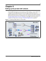
Setting up the private VoIP network . . . . . . . . . . . . . . . . . . . . . . . . . . . . . . .65
To enable MCDN TAT ...................................................................................................69
To enter the QoS settings for VoIP trunks.....................................................................71
To enable fallback .........................................................................................................72
To configure gatekeeper settings for H323 trunks.........................................................73
To configure routing for outgoing calls ..........................................................................74
To configure remote access packages..........................................................................76
To configure destination codes for the PSTN................................................................77
PSTN access and analog devices . . . . . . . . . . . . . . . . . . . . . . . . . . . . . . . .79
To configure the DNs for analog devices ......................................................................80
Troubleshooting . . . . . . . . . . . . . . . . . . . . . . . . . . . . . . . . . . . . . . . . . . . . . . .83
To manually redirect an IP telephone to the main office ...............................................86
Telephone features in normal and local mode . . . . . . . . . . . . . . . . . . . . . .89
Glossary . . . . . . . . . . . . . . . . . . . . . . . . . . . . . . . . . . . . . . . . . . . . . . . . . . . . .97
SRG50 Configuration Guide
4
NN40140-500
5
Contents
Getting started . . . . . . . . . . . . . . . . . . . . . . . . . . . . . . . . . . . . . . . . . . . . . . . . . 9
About this guide . . . . . . . . . . . . . . . . . . . . . . . . . . . . . . . . . . . . . . . . . . . . . . . . . . . . . . . 9
Audience . . . . . . . . . . . . . . . . . . . . . . . . . . . . . . . . . . . . . . . . . . . . . . . . . . . . . . . . . . . . 9
Acronyms . . . . . . . . . . . . . . . . . . . . . . . . . . . . . . . . . . . . . . . . . . . . . . . . . . . . . . . . . . . . 9
Symbols and conventions used in this guide . . . . . . . . . . . . . . . . . . . . . . . . . . . . . . . . 11
Related publications . . . . . . . . . . . . . . . . . . . . . . . . . . . . . . . . . . . . . . . . . . . . . . . . . . 12
How to get help . . . . . . . . . . . . . . . . . . . . . . . . . . . . . . . . . . . . . . . . . . . . . . . . . . . . . . 13
SRG50 overview . . . . . . . . . . . . . . . . . . . . . . . . . . . . . . . . . . . . . . . . . . . . . . . 15
SRG50 creation . . . . . . . . . . . . . . . . . . . . . . . . . . . . . . . . . . . . . . . . . . . . . . . . . . . . . . 16
SRG50 keycode activation . . . . . . . . . . . . . . . . . . . . . . . . . . . . . . . . . . . . . . . . . . . . . 17
SRG50 and BCM50 features comparison . . . . . . . . . . . . . . . . . . . . . . . . . . . . . . . . . . 18
Supported devices . . . . . . . . . . . . . . . . . . . . . . . . . . . . . . . . . . . . . . . . . . . . . . . . . . . . 19
SRG50 terminology . . . . . . . . . . . . . . . . . . . . . . . . . . . . . . . . . . . . . . . . . . . . . . . . . . . 20
Coordination with the main office call server . . . . . . . . . . . . . . . . . . . . . . . . . . . . . . . . 21
SRG operating modes . . . . . . . . . . . . . . . . . . . . . . . . . . . . . . . . . . . . . . . . . . . . . . . . . 21
Normal mode . . . . . . . . . . . . . . . . . . . . . . . . . . . . . . . . . . . . . . . . . . . . . . . . . . . . . 21
Local mode . . . . . . . . . . . . . . . . . . . . . . . . . . . . . . . . . . . . . . . . . . . . . . . . . . . . . . 23
SRG installation and configuration summary . . . . . . . . . . . . . . . . . . . . . . . . . . . . . . . 24
Process map for installing and configuring an SRG . . . . . . . . . . . . . . . . . . . . . . . . . . 26
Task summary . . . . . . . . . . . . . . . . . . . . . . . . . . . . . . . . . . . . . . . . . . . . . . . . 27
Foundation configuration . . . . . . . . . . . . . . . . . . . . . . . . . . . . . . . . . . . . . . . . . . . . . . . 27
IP telephone configuration . . . . . . . . . . . . . . . . . . . . . . . . . . . . . . . . . . . . . . . . . . . . . . 28
Dialing plan configuration . . . . . . . . . . . . . . . . . . . . . . . . . . . . . . . . . . . . . . . . . . . . . . 29
VoIP trunk configuration . . . . . . . . . . . . . . . . . . . . . . . . . . . . . . . . . . . . . . . . . . . . . . . 29
Call routing configuration . . . . . . . . . . . . . . . . . . . . . . . . . . . . . . . . . . . . . . . . . . . . . . . 31
Redirection and call forward configuration . . . . . . . . . . . . . . . . . . . . . . . . . . . . . . . . . 31
CS 1000 considerations. . . . . . . . . . . . . . . . . . . . . . . . . . . . . . . . . . . . . . . . . 33
CS 1000 and SRG terminology comparison . . . . . . . . . . . . . . . . . . . . . . . . . . . . . . . . 33
Normal and local mode overview . . . . . . . . . . . . . . . . . . . . . . . . . . . . . . . . . . . . . . . . 35
Normal mode . . . . . . . . . . . . . . . . . . . . . . . . . . . . . . . . . . . . . . . . . . . . . . . . . . . . . 35
Local mode . . . . . . . . . . . . . . . . . . . . . . . . . . . . . . . . . . . . . . . . . . . . . . . . . . . . . . 35
Survivability . . . . . . . . . . . . . . . . . . . . . . . . . . . . . . . . . . . . . . . . . . . . . . . . . . . . . . 36
Recovery to normal mode . . . . . . . . . . . . . . . . . . . . . . . . . . . . . . . . . . . . . . . . . . . 37
Testing the telephone in local mode . . . . . . . . . . . . . . . . . . . . . . . . . . . . . . . . . . . 37
Virtual trunk capacity . . . . . . . . . . . . . . . . . . . . . . . . . . . . . . . . . . . . . . . . . . . . . . . . . . 38
Vacant Number Routing (VNR) . . . . . . . . . . . . . . . . . . . . . . . . . . . . . . . . . . . . . . . . . . 38
Bandwidth management . . . . . . . . . . . . . . . . . . . . . . . . . . . . . . . . . . . . . . . . . . . . . . . 38
SRG50 Configuration Guide
6
Network Bandwidth Management (NBWM) . . . . . . . . . . . . . . . . . . . . . . . . . . . . . 39
Adaptive Network Bandwidth Management (ADBWM) . . . . . . . . . . . . . . . . . . . . . 39
Alternative Call Routing (ACR) . . . . . . . . . . . . . . . . . . . . . . . . . . . . . . . . . . . . . . . 39
Bandwidth management configuration: NBWM, ADBWM, and ACR . . . . . . . . . . . . . 40
Emergency Services Access (ESA) configuration . . . . . . . . . . . . . . . . . . . . . . . . . . . . 42
CS 1000 information for the SRG . . . . . . . . . . . . . . . . . . . . . . . . . . . . . . . . . . . . . . . . 44
S1000 Main Office Settings panel . . . . . . . . . . . . . . . . . . . . . . . . . . . . . . . . . . . . . 44
IP telephones redirection . . . . . . . . . . . . . . . . . . . . . . . . . . . . . . . . . . . . . . . . . . . . . . . 47
IP telephones numbers and models . . . . . . . . . . . . . . . . . . . . . . . . . . . . . . . . . . . 47
S1000 IP Terminal Details panel . . . . . . . . . . . . . . . . . . . . . . . . . . . . . . . . . . . . . . 48
IP telephone settings . . . . . . . . . . . . . . . . . . . . . . . . . . . . . . . . . . . . . . . . . . . . . . . 50
Firmware upgrade . . . . . . . . . . . . . . . . . . . . . . . . . . . . . . . . . . . . . . . . . . . . . . . . . . . . 51
Supported firmware . . . . . . . . . . . . . . . . . . . . . . . . . . . . . . . . . . . . . . . . . . . . . . . . 51
Firmware upgrade procedure . . . . . . . . . . . . . . . . . . . . . . . . . . . . . . . . . . . . . . . . 51
IP telephones setup and configuration . . . . . . . . . . . . . . . . . . . . . . . . . . . . 53
Registration password . . . . . . . . . . . . . . . . . . . . . . . . . . . . . . . . . . . . . . . . . . . . . . . . . 53
Local mode indication . . . . . . . . . . . . . . . . . . . . . . . . . . . . . . . . . . . . . . . . . . . . . . . . . 55
IP telephone codec and jitter settings . . . . . . . . . . . . . . . . . . . . . . . . . . . . . . . . . . . . . 55
Telephone (DN) records configuration . . . . . . . . . . . . . . . . . . . . . . . . . . . . . . . . . . . . 56
Received numbers configuration . . . . . . . . . . . . . . . . . . . . . . . . . . . . . . . . . . . . . . . . . 59
DHCP settings configuration . . . . . . . . . . . . . . . . . . . . . . . . . . . . . . . . . . . . . . . . . . . . 60
Call forwarding options . . . . . . . . . . . . . . . . . . . . . . . . . . . . . . . . . . . . . . . . . . . . . . . . 60
Configuration settings for redirected phones . . . . . . . . . . . . . . . . . . . . . . . . . . . . . . . . 61
Test Local Mode . . . . . . . . . . . . . . . . . . . . . . . . . . . . . . . . . . . . . . . . . . . . . . . . . . . . . 61
Features in local mode . . . . . . . . . . . . . . . . . . . . . . . . . . . . . . . . . . . . . . . . . . . . . . . . 62
911 Emergency Services Support . . . . . . . . . . . . . . . . . . . . . . . . . . . . . . . . . . . . . . . . 63
Setting up the private VoIP network. . . . . . . . . . . . . . . . . . . . . . . . . . . . . . . 65
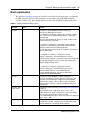
Basic parameters . . . . . . . . . . . . . . . . . . . . . . . . . . . . . . . . . . . . . . . . . . . . . . . . . . . . . 67
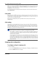
Private dialing plan . . . . . . . . . . . . . . . . . . . . . . . . . . . . . . . . . . . . . . . . . . . . . . . . . . . 68
Meridian Customer Defined Network (MCDN) . . . . . . . . . . . . . . . . . . . . . . . . . . . . . . 69
QoS settings (codec, jitter buffer, and related items) . . . . . . . . . . . . . . . . . . . . . . . . . 70
Network security . . . . . . . . . . . . . . . . . . . . . . . . . . . . . . . . . . . . . . . . . . . . . . . . . . . . . 72
VoIP trunking configuration . . . . . . . . . . . . . . . . . . . . . . . . . . . . . . . . . . . . . . . . . . . . . 72
Fallback configuration . . . . . . . . . . . . . . . . . . . . . . . . . . . . . . . . . . . . . . . . . . . . . . 72
Gatekeeper routing . . . . . . . . . . . . . . . . . . . . . . . . . . . . . . . . . . . . . . . . . . . . . . . . 73
Line pools . . . . . . . . . . . . . . . . . . . . . . . . . . . . . . . . . . . . . . . . . . . . . . . . . . . . . . . . . . 74
Call routing . . . . . . . . . . . . . . . . . . . . . . . . . . . . . . . . . . . . . . . . . . . . . . . . . . . . . . . . . 74
Outgoing calls configuration . . . . . . . . . . . . . . . . . . . . . . . . . . . . . . . . . . . . . . . . . . . . 74
SRG PSTN access . . . . . . . . . . . . . . . . . . . . . . . . . . . . . . . . . . . . . . . . . . . . . . . . . . . 76
Remote Access Package for VoIP trunks . . . . . . . . . . . . . . . . . . . . . . . . . . . . . . . 76
PSTN destination codes configuration . . . . . . . . . . . . . . . . . . . . . . . . . . . . . . . . . 77
NN40140-500
7
Main office information . . . . . . . . . . . . . . . . . . . . . . . . . . . . . . . . . . . . . . . . . . . . . . . . 78
External attendant support . . . . . . . . . . . . . . . . . . . . . . . . . . . . . . . . . . . . . . . . . . . . . 78
PSTN access and analog devices . . . . . . . . . . . . . . . . . . . . . . . . . . . . . . . . 79
PSTN access considerations . . . . . . . . . . . . . . . . . . . . . . . . . . . . . . . . . . . . . . . . . . . . 79
Analog devices considerations . . . . . . . . . . . . . . . . . . . . . . . . . . . . . . . . . . . . . . . . . . 79
Troubleshooting. . . . . . . . . . . . . . . . . . . . . . . . . . . . . . . . . . . . . . . . . . . . . . . 83
IP telephone troubleshooting . . . . . . . . . . . . . . . . . . . . . . . . . . . . . . . . . . . . . . . . . . . . 83
IP terminal details . . . . . . . . . . . . . . . . . . . . . . . . . . . . . . . . . . . . . . . . . . . . . . . . . . . . 84
Probable causes for redirection failure . . . . . . . . . . . . . . . . . . . . . . . . . . . . . . . . . . . . 85
Troubleshooting fallback to local mode . . . . . . . . . . . . . . . . . . . . . . . . . . . . . . . . . . . . 86
IP telephones manual redirection . . . . . . . . . . . . . . . . . . . . . . . . . . . . . . . . . . . . . . . . 86
Cannot clear alarms using an alarm set . . . . . . . . . . . . . . . . . . . . . . . . . . . . . . . . . . . 87
Telephone features in normal and local mode . . . . . . . . . . . . . . . . . . . . . . 89
Normal mode . . . . . . . . . . . . . . . . . . . . . . . . . . . . . . . . . . . . . . . . . . . . . . . . . . . . . . . . 89
Local mode . . . . . . . . . . . . . . . . . . . . . . . . . . . . . . . . . . . . . . . . . . . . . . . . . . . . . . . . . 89
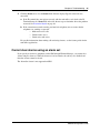
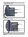
IP Phone 1110 in Local mode . . . . . . . . . . . . . . . . . . . . . . . . . . . . . . . . . . . . . . . . 90
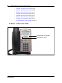
IP Phone 1120E in Local mode . . . . . . . . . . . . . . . . . . . . . . . . . . . . . . . . . . . . . . . 91
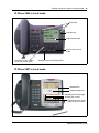
IP Phone 1140E in Local mode . . . . . . . . . . . . . . . . . . . . . . . . . . . . . . . . . . . . . . . 91
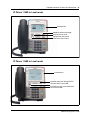
IP Phone 2001 in Local mode . . . . . . . . . . . . . . . . . . . . . . . . . . . . . . . . . . . . . . . . 92
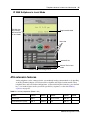
IP Phone 2002 in Local mode . . . . . . . . . . . . . . . . . . . . . . . . . . . . . . . . . . . . . . . . 92
IP Phone 2004 in Local mode . . . . . . . . . . . . . . . . . . . . . . . . . . . . . . . . . . . . . . . . 93
IP Phone 2007 in Local mode . . . . . . . . . . . . . . . . . . . . . . . . . . . . . . . . . . . . . . . . 93
IP Phone 2033 in Local mode . . . . . . . . . . . . . . . . . . . . . . . . . . . . . . . . . . . . . . . . 94
IP 2050 Softphone in Local Mode . . . . . . . . . . . . . . . . . . . . . . . . . . . . . . . . . . . . . 95
ATA extension features . . . . . . . . . . . . . . . . . . . . . . . . . . . . . . . . . . . . . . . . . . . . . . . . 95
Glossary . . . . . . . . . . . . . . . . . . . . . . . . . . . . . . . . . . . . . . . . . . . . . . . . . . . . . 97
SRG50 Configuration Guide
8
NN40140-500
9
Chapter 1
Getting started
About this guide
The SRG50 Configuration Guide describes how to install, configure, and maintain the Survivable
Remote Gateway (SRG) 50 Release 3.0.
The SRG50 is positioned as a cost-effective Small IP Branch Office solution for CS 1000 Main
office systems. The SRG50 offers business continuity and public switched telephone network
(PSTN) failover for voice over IP (VoIP) networks. An SRG provides transparent operation,
feature and application parity with a main office call server while in normal operating mode. If
connectivity with the call server or wide area network (WAN) is lost, the normal mode sets revert
back to local mode. The SRG takes ownership of call control for the local sets automatically and
provides internal communications as well as external connectivity to the PSTN.
SRG50 supports H323 and SIP Trunking and up to 80 survivable IP users with a single SRG
application authorization code. It is provided as a cost-effective VoIP business continuity solution
for small branch offices. The SRG50 supports CS 1000 Release 4.0, 4.5, 5.0, and 5.5.
Audience
The SRG50 Configuration Guide is intended for two audiences:
•
•
the individuals responsible for engineering the SRG50 site and installing the BCM50,
configuring it for operation as an SRG50, and connecting it to the network
the individuals responsible for post-installation system administration and
maintenance.
The SRG50 site engineer and installer must be familiar with BCM50 hardware and software, and
IP telephony and VoIP trunk configuration on the BCM50.
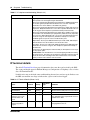
Acronyms
The following is a list of acronyms used in this guide.
Table 1 Acronyms used in this guide (Sheet 1 of 2)
Acronym
Description
ACR
Alternative call routing
ANBWM
Adaptive network bandwidth management
ASM
Analog station module
ATA
Analog terminal adapter
SRG50 Configuration Guide
10
Chapter 1 Getting started
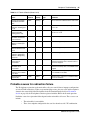
Table 1 Acronyms used in this guide (Sheet 2 of 2)
Acronym
Description
BARS
Basic alternate route selection
BUID
Branch user ID
CDP
Coordinated dialing plan
DDIM
Digital drop and insert mux
DN
Directory number
DSC
Distant steering codes
DSM
Digital station module
DTM
Digital trunk module
ESA
Emergency services access
ESDN
Emergency services DN
FRL
Facility restriction level
GATM
Global analog trunk module
KEM
Key expansion module
KRS
Keycode retrieval system
LAN
Local area network
LSC
Local steering codes
MCDN
Meridian customer defined network
MOTN
Main office terminal number
MVC
Mobile voice client
NARS
Network alternate route selection
NBWM
Network bandwidth management
NCS
Network connection server
NRS
Network routing service
PSTN
Public switched telephone network
QoS
Quality of service
SPN
Special number
SRG
Survivable remote gateway
TAT
Trunk anti-tromboning
TRO
Trunk route optimization
TSC
Trunk steering codes
UDP
Uniform dialing plan
VNR
Vacant number routing
VoIP
Voice over internet protocol
VPN
Virtual private network
VPNI
Virtual private network ID
WAN
Wide area network
ZDP
Zone digit prefix
NN40140-500
Chapter 1 Getting started
11
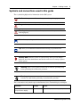
Symbols and conventions used in this guide
These symbols highlight critical information for the SRG system.
Caution: Alerts you to conditions where you can damage the equipment.
Danger: Alerts you to conditions where you can get an electrical shock.
Warning: Alerts you to conditions where you can cause the system to fail or
work improperly.
Note: Alerts you to important information.
Tip: Alerts you to additional information that can help you perform a task.
!
Security Note: Indicates a point of system security where you can change a
default or where the administrator must decide on the level of security required
for the system.
Warning: Alerts you to ground yourself with an antistatic grounding strap
before performing the maintenance procedure.
Warning: Alerts you to remove the main unit and expansion unit power cords
from the AC outlet before performing any maintenance procedure.
These conventions and symbols represent the Business Series Terminal display and dialpad.
Convention
Example
Used for
Word in a special font (shown in
the top line of the display)
Pswd:
Command line prompts on display telephones.
SRG50 Configuration Guide
12
Chapter 1 Getting started
Convention
Example
Used for
Underlined word in capital letters
(shown in the bottom line of a
two-line display telephone)
PLAY
Display options on two-line display telephones.
Press the button directly below the option on the
display to proceed.
Dialpad buttons
£
Buttons you press on the dialpad to select a
particular option.
These text conventions are used in this guide to indicate the information described.
Convention
Description
bold Courier
text
Indicates command names, options, and text that you must enter.
Example: Use the info command.
Example: Enter show ip {alerts|routes}.
italic text
Indicates book titles.
plain Courier
text
Indicates command syntax and system output (for example, prompts
and system messages).
Example: Set Trap Monitor Filters
FEATURE
HOLD
RELEASE
Indicates that you press the button with the corresponding icon on the
set you are using.
Related publications
This section provides a list of additional documents referred to in this guide.
Administration Guide (NN40020-600)
Device Configuration Guide (NN40020-300)
Installation Checklist and Quick Start Guide (NN40020-308)
Installation and Maintenance Guide (NN40020-302)
Main Office Configuration Guide for SRG50 (NN43001-307)
Networking Configuration Guide (NN40020-603)
Telephony Device Installation Guide (NN40020-309)
NN40140-500
Chapter 1 Getting started
13
How to get help
This section explains how to get help for Nortel products and services.
Getting Help from the Nortel Web site
The best way to get technical support for Nortel products is from the Nortel Technical Support
Web site:
http://www.nortel.com/support
This site provides quick access to software, documentation, bulletins, and tools to address issues
with Nortel products. More specifically, the site enables you to:
•
•
•
•
download software, documentation, and product bulletins
search the Technical Support Web site and the Nortel Knowledge Base for answers to
technical issues
sign up for automatic notification of new software and documentation for Nortel
equipment
open and manage technical support cases
Getting Help over the phone from a Nortel Solutions Center
If you don’t find the information you require on the Nortel Technical Support Web site, and have a
Nortel support contract, you can also get help over the phone from a Nortel Solutions Center.
In North America, call 1-800-4NORTEL (1-800-466-7835).
Outside North America, go to the following Web site to obtain the phone number for your region:
http://www.nortel.com/callus
Getting Help from a specialist by using an Express Routing Code
To access some Nortel Technical Solutions Centers, you can use an Express Routing Code (ERC)
to quickly route your call to a specialist in your Nortel product or service. To locate the ERC for
your product or service, go to:
http://www.nortel.com/erc
Getting Help through a Nortel distributor or reseller
If you purchased a service contract for your Nortel product from a distributor or authorized
reseller, contact the technical support staff for that distributor or reseller.
SRG50 Configuration Guide
14
Chapter 1 Getting started
NN40140-500
15
Chapter 2
SRG50 overview
The SRG50 is a software application that leverages the BCM50 platform. It is optimized to
provide feature transparency to the main office call server and to act as a survival remote gateway
in a CS 1000 IP branch office environment.
SRG50 supports up to 80 survivable IP users with a single SRG application authorization code.
SRG50 Release 3.0 operates with CS 1000 running Release 4.0, 4.5, 5.0, and 5.5.
Configure SRG50 with Business Element Manager (Element Manager) or Network Configuration
Manager (NCM). For detailed information about managing SRG50 with NCM, see your NCM
documentation.
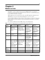
For a summary of differences between SRG versions, see the following table.
Table 2 Summary of supported features on the different SRG versions (Sheet 1 of 2)
Features
SRG 1.5 on BCM 200/ SRG50 1.0
400
SRG50 2.0
SRG50 3.0
Platform
Available on BCM 200/
400 hardware.
SRG 1.5 is not
available on BCM1000
hardware.
Available on standard
BCM50 hardware.
SRG50 1.0 is not
available on BCM50a
or BCM50e hardware.
Available on standard
BCM50 and BCM50b
hardware only.
SRG50 2.0 is not
available on BCM50a,
BCM50ba, BCM50e,
and BCM50be
hardware.
Available on standard
BCM50 and BCM50b
hardware only.
SRG50 3.0 is not
available on BCM50a,
BCM50ba, BCM50e,
and BCM50be
hardware.
Call Servers
CS1000 Release 3.0,
4.0, and 4.5
CS1000 Release 3.0,
4.0, and 4.5
CS1000 Release 4.0,
4.5, and 5.0
CS1000 Release
4.0,4.5, and 5.0
Trunking
H323 is supported.
H323 is supported.
When CS1000 is
supported by SRG,
both H323 and SIP
trunks are supported
between them.
H323 and SIP trunking
are supported.
IP clients
IP Phones 2001, 2002
(phase 1 and 2), 2004
(phase 1 and 2), 2007.
IP KEM, IP Phone
2050 series.
IP Phone 1110, 1120,
1140, IP Phone 2033
(polycom), WLAN
2210/2211/2212.
IP Phones 2001, 2002
(phase 1 and 2), 2004
(phase 1 and 2), 2007.
IP KEM, IP Phone
2050 (v1).
IP Phone 2033
(polycom), 2122
IP Phones 2001, 2002
(phase 1 and 2), 2004
(phase 1 and 2), 2007.
IP KEM, IP Phone
2050 series.
IP Phone 1120, 1140,
IP Phone 2033
(polycom), WLAN
2210/2211/2212.
IP Phones 2001, 2002
(phase 1 and 2), 2004
(phase 1 and 2), 2007.
IP KEM, IP Phone
2050 series.
IP Phone 1110, 1120,
1140, IP Phone 2033
(polycom), WLAN
2210/2211/2212.
Number of IP
clients
supported
90
32
80
80
NetIQ
Not supported
Not supported
Supported
Supported
PVQM
Not supported
Not applicable
Supported
Supported
SRG50 Configuration Guide
16
Chapter 2 SRG50 overview
Table 2 Summary of supported features on the different SRG versions (Sheet 2 of 2)
Features
SRG 1.5 on BCM 200/ SRG50 1.0
400
SRG50 2.0
SRG50 3.0
ESA
Supported
Supported
Supported
Supported.
On Site Notification
(OSN) of E911 alarms
supported for local
users through a third
party tool.
Vo911
Supported
Supported
Supported
Supported.
Enhanced
firmware
download
Supported
Supported
Supported
Supported
Analog station
support
The number supported
depends on the
hardware.
For BCM200: two
analog station modules
are supported.
number of analog
nodes= 2*8 =16.
For BCM400: Four
analog station modules
are supported.
number of analog
nodes= 4*8 =32)
Two analog station
modules are
supported.
number of analog
nodes= 2*8 =16)
Two analog station
modules are
supported.
number of analog
nodes= 2*8 =16)
Two analog station
modules are
supported.
number of analog
nodes= 2*8 =16)
SRG50 creation
An SRG50 is created by applying the appropriate SRG keycode to a functional BCM50 system.
SRG50 is only supported on the BCM50 and BCM50b main units. Integrated router versions of
the BCM50 (BCM50a, BCM50e, BCM50ba, and BCM50be) do not support the SRG50
application.
The Installation Checklist and Quick Start Guide is provided on the SRG50 Documentation CD
that is shipped with your SRG50 system. Instructions in that guide are referenced in the following
procedures. Also, the relevant BCM50 default IP addresses, user names, and passwords are
excerpted from that guide and provided for your reference in the table BCM50 default IP addresses
on page 16 and the table BCM50 default user names and passwords on page 17.
Table 3 BCM50 default IP addresses
Port
IP address
Subnet mask
OAM port (see Note)
10.10.11.1
255.255.255.252
BCM50 LAN (no router)
192.168.1.2
255.255.255.0
Note: DHCP is enabled on the OAM port and assigns the following IP address: 10.10.11.2
NN40140-500
Chapter 2 SRG50 overview
17
Table 4 BCM50 default user names and passwords
Tool
User ID| User Name
Password
Element Manager
nnadmin
PlsChgMe!
Onbox main web page
(http:// [IP address]
nnadmin
PlsChgMe!
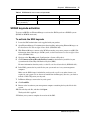
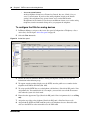
SRG50 keycode activation
To create an SRG50, use Element Manager to activate the SRG keycode on a BCM50 system
(BCM50 or BCM50b main unit).
To activate the SRG keycode
1
Locate the SRG authorization codes supplied with your product.
2
Open Element Manager. For information about installing and opening Element Manager, see
the Installation Checklist and Quick Start Guide (NN40020-308).
3
With Element Manager, connect to the BCM system that you want to convert to an SRG. For
information about connecting to a BCM system, see the Installation Checklist and Quick Start
Guide (NN40020-308).
4
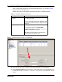
Navigate to the Keycodes panel (Configuration > System > Keycodes).
5
Click Connect to Nortel Keycode Retrieval system to obtain the keycode file for your
system from the Nortel Keycode Retrieval System (KRS).
For more information about keycodes, see the Keycode Installation Guide (NN40010-301).
6
In the KRS, generate the keycode file for your system and save it on your management
computer.
Make sure the SRG feature is included in your keycode as well as any other features you
require for your system. To use the on-site notification for Emergency Services, you need to
include a LAN CTE port in your keycode.
7
In Element Manager, return to the keycodes panel.
8
Click Load File.
9
Browse to the location on your management computer containing the keycode file for this
system.
10 Select the keycode file, and then click Open.
The keycode file is applied.
11 Reboot your system to complete the creation of the SRG.
SRG50 Configuration Guide
18
Chapter 2 SRG50 overview
To reboot the system
1
In Element Manager, navigate to the Reset panel (Administration > Utilities > Reset).
2
Click Reboot BCM50 System.
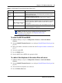
To verify that the SRG has been successfully created
1
In Element Manager, navigate to the Keycodes panel (Configuration > System > Keycodes).
In the Feature licenses table, verify that the status of the SRG keycode is ACTIVE.
2
Open the Resources folder (Configuration > Resources).
Verify that there is a Survivable Remote Gateway panel.
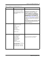
SRG50 and BCM50 features comparison
The table Comparison of BCM50 and SRG50 on page 18 compares SRG50 and BCM50 features.
Table 5 Comparison of BCM50 and SRG50 (Sheet 1 of 2)
Item
BCM50
SRG50
MBMs
See the
Installation and
Maintenance
Guide
(NN40020-302)
Recommended:
ASM8+ (8 port Analog Station Module); DTM
(Digital Trunk Module - 24 lines on either T1
or E1 or PRI); BRI (4 line BRI S/T Module);
GATM4 (Global Analog Trunk MBM - 4 port);
GATM8 (Global Analog Trunk MBM - 8 port)
ADID4 (4 analog lines)
ADID8 (8 analog lines)
G4x16 (16 digital ports and 4 analog trunks);
G8x16 (16 digital ports and 8 analog trunks)
Supported for ATA connections:
DSM16 (Digital Station Module - 16 ports);
DSM32 (Digital Station Module - 32 ports);
4x16 Combo (16 digital ports, 4 analog
trunks and 1 analog station);
Does not support:
DDIM (Digital Drop and Insert Mux)
FEM (Fiber Expansion Module)
DECT (Digital Enhanced Cordless
Telecommunications)
Digital telephone sets
Yes
No
FCAPS
Yes
Yes, extended to include SRG-specific
alarms and keycodes
Network Configuration Manager
Yes
Yes
Telset Administration
Yes
No
CS 1000 Geographic Redundancy
N/A
Yes
CS 1000 Network Bandwidth Management
N/A
Yes
NN40140-500
Chapter 2 SRG50 overview
19
Table 5 Comparison of BCM50 and SRG50 (Sheet 2 of 2)
Item
BCM50
SRG50
CS 1000 Adaptive Network Bandwidth Management N/A
Yes
CS 1000 Alternative Call Routing
N/A
Yes
CS 1000 Emergency Services Access
N/A
Yes
Firmware Download from main office call server
N/A
Yes (CS 1000 Release 4.0, 4.5, 5.0, and 5.5)
(CS 1000 Release 4.0 requires patch
MPLR22418)
SRG-specific features for interaction with a main
office call server, including: Heartbeat detection of
WAN recovery; IP telephone redirection to main
office in Normal Mode; Local Mode IP telephone
interface; H.323 Gateway to PSTN under control of
main office call server
N/A
Yes
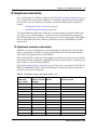
Supported devices
The SRG50 Release 3.0 supports:
•
•
•
•
•
•
•
•
•
IP Phones 1110, 1120E, and 1140E
IP Phone 2001, 2002, 2004, 2007, and 2033
IP Phone Key Expansion Module (KEM) – The IP Phone KEM is supported on an
SRG with normal mode IP Phones. It does not function with local mode or test local
mode IP Phones.
IP Softphone 2050 v1/v2 and Mobile Voice Client (MVC) 2050
WLAN Handsets 2210, 2211, and 2212
WLAN Handsets 6120 and 6140
WLAN Handsets 1210, 1220, and 1230
Analog (500/2500 type) telephones
Analog devices such as fax machines
Note: Throughout this document, the IP Phones in this list are referred to collectively as
IP Phones.
The SRG50 is positioned primarily to support IP telephones and clients. However, analog devices
can be supported using analog station modules (ASM), or by using an analog terminal adapter
(ATA2) in conjunction with a digital station module (DSM). The SRG50 does not support digital
or ISDN telephones.
SRG50 Configuration Guide
20
Chapter 2 SRG50 overview
SRG50 terminology
The table SRG50 terminology on page 20 identifies SRG terms that may be unfamiliar to main
office installers. They are provided to facilitate communications between SRG and main office
personnel. In the table, the Element Manager path where the term appears is provided for reference
and may not represent every appearance of the term.
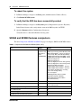
Table 6 SRG50 terminology (Sheet 1 of 2)
Term
Description
Port
For telephony configuration (Configuration > Telephony), a port is an internal number that
identifies a physical termination point for a telephone set or a physical trunk.
For the configuration of resources (Configuration > Resources) and data services
(Configuration > Data Services), port is used in the context of the TCP/IP protocol suite.
IP Terminal
IP telephone
Configuration > Resources > Telephony Resources > IP & App Sets
Sets
Can refer to actual telephones, or to the directory number (DN) assigned to the port to
which a particular telephone is connected.
Telephone
Configuration > Resources > Telephony Resources > IP & App Sets
Mapping DN to Telephone
Configuration > Telephony > Sets
DN
Configuration > Telephony > Lines > Target Lines > Target Lines table > Control Set and
Prime Set columns
Trunks
Trunks refer to external facilities that are connected to the SRG and provide incoming and
outgoing communication paths. Paths can be physical (examples: loop; PRI; T1) or virtual
(VoIP trunks).
Configuration > Resources
Loop trunk
An analog loop (FXO) that connects to the PSTN: a POTS line.
Lines
A line is the generic term used for all communication paths, both internal and external.
Configuration > Telephony > Lines
Physical Lines
Physical trunks.
Configuration > Telephony > Lines > Active Physical Lines
(Lines 061 to 124)
VoIP Lines
VoIP trunks.
Configuration > Telephony > Lines > Active VoIP Lines
(Lines 001 to 024)
NN40140-500
Chapter 2 SRG50 overview
21
Table 6 SRG50 terminology (Sheet 2 of 2)
Term
Description
Target Lines
Target lines are internal, virtual paths between trunks and telephones for incoming calls
(only). They provide flexibility in the way trunks and telephones can be associated: target
lines can be used to direct an incoming call to one or more telephones, direct one or
more trunks to one phone, or direct several trunks (in a line pool) to one or more phones.
Target lines are assigned to DNs. A target line triggers ringing voltage to the telephone(s)
connected to the port(s) associated with the DN(s) that the target line is assigned to. (For
example, if a unique target line is assigned to each DN, only one telephone rings when
the DN is called. If several DNs are assigned to one target line, calling any of the DNs
ring all of the associated phones.)
Target lines are required for auto-answer trunks. Because VoIP lines are set internally to
auto-answer, target lines are required for SRG operation.
Element Manager provides two methods for assigning target lines to DNs.
1) Configuration > Telephony > Sets > All DNs > All DNs table > Details for DN subpanel
> Line Assignment tab
or
2) Configuration > Telephony > Lines > Target Lines > Target Lines table > Details for
Line subpanel > Assigned DNs tab
The first method provides a convenient way to assign the target line to the DN when the
DN record is configured. The second method provides fields that allow incoming digit
strings to be mapped to the DN.
(Lines 125 to 268)
For more information about target lines, see the Networking Configuration Guide
(NN40020-603).
Line pool
Several of the same type of trunk configured as one group: a trunk group.
Coordination with the main office call server
Configuration of the SRG branch office requires datafill at both the SRG and the main office call
server. Main office configuration drives SRG configuration, and Nortel recommends that the main
office activities be concluded before undertaking SRG configuration.
For information, see CS 1000 considerations on page 33.
SRG operating modes
The SRG has two operating modes:
•
•
Normal mode
Local mode
Normal mode
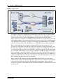
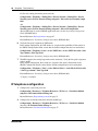
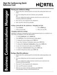
In normal mode (see the figure Normal mode on page 22), the SRG is connected to the main office
call server over a WAN using VoIP trunks. From the perspective of the main office, the SRG is a
branch office.
SRG50 Configuration Guide
22
Chapter 2 SRG50 overview
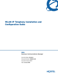
Figure 1 Normal mode
Main office
Branch office
SRG
IP phones
IP phones
WLAN
handsets
Software
phones
VoIP connection over WAN
Normal mode
IP telephones connected at the SRG are registered with the main office call server and are under
main office control. They operate as branch user sets and have access to all telephony services and
features that the call server offers to IP telephones connected directly to the main office.
When a branch user set initiates a local PSTN call, the main office sets up the call using the VoIP
trunks, which establishes a local media path. Emergency Services Access calls are similarly routed
to the SRG PSTN. The telephone is redirected to local mode and the SRG initiates a local PSTN
call to 911. For main office callers, the SRG acts as a VoIP-PSTN gateway during normal mode.
When call forwarding has been configured, incoming PSTN calls to the branch user set are
forwarded over VoIP trunks (either H.323 or SIP) to the main office, which terminates the call at
the branch user. Similarly, calls from analog telephones connected to the SRG to the branch user
set are forwarded to the main office over VoIP trunks, which then terminates the call at the branch
user. Calls from the branch user set to the analog telephones at the SRG are routed over the VoIP
trunks to terminate at the analog telephone. In all these call scenarios, only signaling messages go
through the VoIP trunk. The media path is set up directly between the branch user set and the voice
gateway at the SRG. This means that these calls do not use any WAN bandwidth between the main
office and the branch office after calls are established.
When a branch user IP telephone calls a main office IP telephone and vice versa, the call is a
simple station-to-station call within the main office call server. Since the branch user IP telephone
is physically remote from the call server, the media path goes through the WAN connection
between the main office and the SRG, and thus uses WAN bandwidth, as demanded by the codec
used in the call.
NN40140-500
Chapter 2 SRG50 overview
23
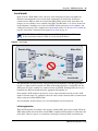
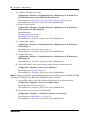
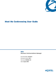
Local mode
In the event of a WAN failure or the call server at the main office becomes unavailable, the
IP Phones in normal mode revert to local mode automatically. In local mode, the IP users
connected to the SRG are under the control of the SRG. When in local mode, main office call
features are not available to users attached to the SRG. The SRG offers a set of basic features for
the IP telephones, including access to the local PSTN, dialing emergency service numbers, and
calling local extensions. For a complete list of local mode features, see Features in local mode on
page 62. Local mode is illustrated in the figure Local mode on page 23.
Note: The IP Phone KEM is supported on an SRG with normal mode IP Phones.
It does not function with local mode or test local mode IP Phones.
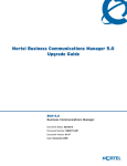
Figure 2 Local mode
Main office
Branch office
SRG
IP phones
IP phones
WAN connectivity lost,
PSTN provides fallback
WLAN
handsets
Software
phones
SRG polling
Local mode
The SRG handles all call processing. Calls between two IP telephones at the SRG are handled
locally as a simple station-to-station call. When an IP telephone initiates a local PSTN call, the
SRG routes the call to a trunk that is connected to the local PSTN. Incoming DID calls are also
handled by the SRG and terminated on the appropriate IP telephone set.
In local mode, the IP telephones do not have access to the main office network over the VoIP
trunks. If alternate routes are configured, then calls can be made to the main office or other branch
offices using the available PSTN trunks.
Several situations, described below, can cause the IP phone to be in local mode.
Initial registration
When the IP telephone is installed, it first registers with the SRG, and is in local mode. When the
SRG configuration at the main office and the SRG is complete the IP telephone is redirected to the
main office, where it registers as a branch user and changes from local mode to normal mode.
SRG50 Configuration Guide
24
Chapter 2 SRG50 overview
Automatic registration with the main office
When configured as a branch office user set, an IP telephone at the SRG automatically attempts to
register with the main office when:
•
•
•
The phone is in local mode because of loss of connectivity with the main office, and
the SRG is redirecting it back to the main office because connectivity has been
reestablished (see Loss of WAN or VoIP connectivity on page 24).
The phone is in local mode because Test Local Mode was invoked and the timer has
expired or the Exit button is pressed.
The phone is in local mode, the main office is a CS 1000, and this is the first time that
the phone has been redirected to the main office.
The IP telephone can fail to register with the main office for several reasons. These are detailed in
Probable causes for redirection failure on page 85.
Loss of WAN or VoIP connectivity
The WAN or VoIP connectivity between the main office and the SRG can become unavailable if,
for example, router failure occurs, the main office becomes unavailable, a WAN failure occurs, or
the VoIP trunks reach capacity. When VoIP connectivity is lost, each IP telephone loses its
connection with the main office terminal proxy server. The IP telephones reboot and reregister at
the SRG, placing them in local mode. If enabled, call forwarding to the main office is
automatically cancelled.
The IP telephones remain under the control of the SRG until VoIP connectivity is confirmed.
When confirmation is received, the IP telephones are automatically redirected to the main office;
redirection requires no user intervention. If the telephone is busy at the time that connectivity is
reestablished, the SRG redirects the phone when it is free.
Test Local Mode
Test Local Mode is a facility that allows the IP telephone to be redirected back to the SRG when it
is in normal mode. This forces the IP telephone to go into local mode and allows the telephone
user or system administrator to test local mode operation without taking down the VoIP trunks to
the main office. Implementation of Test Local Mode depends on the main office call server. For
more information, see CS 1000 considerations on page 33.
SRG installation and configuration summary
The SRG50 Configuration Guide provides information specific to configuring a BCM50 as an
SRG. Information pertaining to generic BCM50 practices and procedures is provided in the
BCM50 documentation suite.
Generally, SRG50 activities leverage an installer’s general knowledge of BCM50 activities.
However, Nortel recommends that the BCM50/SRG50 site engineer and installer familiarize
themselves with SRG-specific requirements before starting any installation activities.
NN40140-500
Chapter 2 SRG50 overview
25
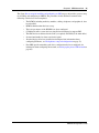
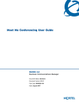
The figure Process map for installing and configuring an SRG on page 26 provides a process map
for installing and configuring an SRG50. The procedures in this document assume that the
following activities have been completed:
•
•
•
•
•
•
•
•
The BCM50, including media bay modules, cabling, telephones, and peripherals, have
been installed.
BCM50 administration has been set up.
The basic parameters of the BCM50 have been configured.
CS1000 main office system has been installed and configured to support SRG.
The SRG has been connected to the LAN (as required) and WAN (to the main office).
System functionality has been tested to this point.
Attached devices have been installed and configured (for information about
configuring IP Phones, see IP telephones setup and configuration on page 53).
Non-SRG-specific networking and device configuration has been completed (for
information about configuring the network, see Setting up the private VoIP network on
page 65).
SRG50 Configuration Guide
26
Chapter 2 SRG50 overview
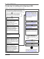
Process map for installing and configuring an SRG
Figure 3 Process map for installing and configuring an SRG
The main office is installed and running and the
information to support SRG has been configured.
You have reviewed the SRG and BCM50
system requirements and documentation.
Install and configure attached
devices. See IP telephones setup
and configuration on page 53 when
configuring the IP telephones. See
PSTN access and analog devices on
page 79 when setting up analog
trunks and devices.
Locate the BCM50 that will be
converted to the SRG.
Install the physical components,
including media bay modules,
cabling, telephones, and
peripherals, as per the Installation
and Maintenance Guide.
Configure the basic parameters of the
BCM50 as per the Installation
Checklist and Quick Start Guide. (see
the Installation and Maintenance
Guide (NN40020-302) and the
Administration Guide (NN40020-600)).
Set up the IP telephones for SRG
operation, as per IP telephones
setup and configuration on page 53.
Set up the private VoIP network, as
per Setting up the private VoIP
network on page 65.
Configure the server-specific data for
the main office call server (see the
documentation for your call server).
Create the SRG (see SRG50 creation
on page 16).
Complete the initial installation,
connect the SRG to the LAN (as
required) and WAN (to main office),
and test the SRG system, as per the
Installation and Maintenance Guide
(NN40020-302).
Set up SRG administration, and
carry out non-SRG-specific
networking and device configuration
as per the Administration Guide
(NN40020-600), the Networking
Configuration Guide (NN40020-603),
and the Device Configuration
Guide (NN40020-300).
NN40140-500
Register each telephone
with the main office and the
SRG.
Troubleshoot any registration issues
(Troubleshooting on page 83).
Test the telephones and analog
equipment in normal mode.
Familiarize users with the services for
local mode. (Telephone features in
normal and local mode on page 89)
27
Chapter 3
Task summary
The task summary offers a high level, chronological review of the tasks required to configure the
SRG50. The paths (Xxxx > Yyyy > Zzzz) direct you to the appropriate Business Element Manager
(Element Manager) panels.
Foundation configuration
Foundation configuration refers to configuration that is done as part of BCM50 foundation
activities. The items identified here are significant for SRG operation and main office planning
and installation.
1
Configure the SRG IP address, net mask, and gateway.
Configuration >System > IP Subsystem
External Reference: Installation and Maintenance Guide (NN40020-302)
2
Confirm the number of IP sets and VoIP trunks.
Configuration > Resources > Application Resources
The Licence column indicates the number of resources available.
External Reference: Keycode Installation Guide (NN40010-301)
3
Verify the global telephony settings.
Configuration > Telephony > Global Settings
External Reference: Device Configuration Guide (NN40020-300)
4
Configure the Start DN (determined by the dialing plan).
Administration > Utilities > Reset > Cold Reset Telephony Services button > Cold Reset
Telephony dialog box > Start DN field
Internal Reference: Basic parameters on page 67
External Reference: Installation and Maintenance Guide (NN40020-302)
5
Verify the DN length.
i) For local calls between telephones on the SRG.
Configuration > Telephony > Dialing Plan > General > Dialing Plan - General panel >
Global Settings subpanel > DN length (intercom) field
ii) For incoming calls from the PSTN
Configuration > Telephony > Dialing Plan > Public Network > Dialing Plan - Public
Network panel> Public Network Settings subpanel > Public Received number length
field
SRG50 Configuration Guide
28
Chapter 3 Task summary
iii) For calls coming in from the private network
Configuration > Telephony > Dialing Plan > Private Network > Dialing Plan - Private
Network panel > Private Network Settings subpanel > Private Received number length
field
and
Configuration > Telephony > Dialing Plan > Private Network > Dialing Plan - Private
Network panel > Private Network Settings subpanel > Private DN length field
(Private DN length is used for DPNSS applications only. See the Networking Configuration
Guide (NN40020-603).)
Internal Reference: Basic parameters on page 67
External Reference: Networking Configuration Guide (NN40020-603)
6
Verify the line pool assignment of VoIP trunks.
In the default configuration, the VoIP trunks are assigned to line pool BlocA. Instructions in
the SRG50 Configuration Guide assume that the default configuration has been maintained.
Configuration > Telephony > Lines > Active VoIP Lines > Active VoIP Lines table > Line
Type column > Line Type field
External Reference: Networking Configuration Guide (NN40020-603)
7
The SRG supports four analog loop trunks on the main unit*. Verify the line pool assignment
of these trunks.
In the default configuration, these trunks are assigned to line pool A. Instructions in the
SRG50 Configuration Guide assume that the default configuration has been maintained.
Configuration > Telephony > Lines > Active Physical Lines > Active Physical Lines table
> Line Type column > Line Type field
External Reference: Networking Configuration Guide (NN40020-603)
* Category 1 countries
IP telephone configuration
1
Configure the registration password.
Configuration > Resources > Telephony Resources > IP Sets row > Details for Module
subpanel > IP Terminal Global Settings tab
Internal Reference: Registration password on page 53
2
Configure the local mode indication (Advertisement/Logo).
Configuration > Resources > Telephony Resources > IP Sets row > Details for Module
subpanel > IP Terminal Global Settings tab
Internal Reference: Local mode indication on page 55
NN40140-500
Chapter 3 Task summary
3
29
Configure the IP telephone codec and jitter settings.
Configuration > Resources > Telephony Resources > IP Sets row > Details for Module
subpanel > IP Terminal Global Settings tab
Internal Reference: IP telephone codec and jitter settings on page 55
4
Configure the telephone (DN) records.
Configuration > Telephony > Sets > All DNs
Internal References: Telephone (DN) records configuration on page 56
5
Configure the received numbers.
Configuration > Telephony > Lines > Target Lines
Internal Reference: Received numbers configuration on page 59
External Reference: Networking Configuration Guide (NN40020-603)
6
Decide on the call forwarding option.
Internal Reference: Call forwarding options on page 60
7
Configure the IP telephones.
Internal Reference: Configuration settings for redirected phones on page 61
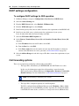
Dialing plan configuration
1
Configure the private network type (CDP or UDP).
Configuration > Telephony > Dialing Plan > Private Network > Dialing Plan - Private
Network panel > Private Network Settings subpanel > Private network type
Internal Reference: Private dialing plan on page 68
External Reference: Networking Configuration Guide (NN40020-603)
2
Enable MCDN TAT.
Configuration > Telephony > Dialing Plan > Private Network > Dialing Plan - Private
Network panel > MCDN subpanel
Internal Reference: Meridian Customer Defined Network (MCDN) on page 69
External Reference: Networking Configuration Guide (NN40020-603)
VoIP trunk configuration
Your SRG VoIP trunks are either H323 trunks, SIP trunks, or a combination of both types.
1
Configure routing table.
Configuration > Resources > Telephony Resources > Modules panel > IP Trunks row >
Routing Table.
External Reference: Networking Configuration Guide (NN40020-603)
SRG50 Configuration Guide
30
Chapter 3 Task summary
2
Configure VoIP trunk QoS settings.
Configuration > Resources > Telephony Resources > Modules panel > IP Trunks row >
H323 Media Parameters tab or SIP Media Parameters tab
Internal Reference: QoS settings (codec, jitter buffer, and related items) on page 70
External Reference: Networking Configuration Guide (NN40020-603)
3
Enable or disable fallback.
Configuration > Resources > Telephony Resources > Modules panel > IP Trunks row >
H323 Settings tab or SIP Settings tab
Internal References:
Fallback configuration on page 72
SRG PSTN access on page 76
External Reference: Networking Configuration Guide (NN40020-603)
4
Configure H323 settings.
Configuration > Resources > Telephony Resources > Modules panel > IP Trunks row >
H323 Settings tab
Internal Reference: Gatekeeper routing on page 73
External Reference: Networking Configuration Guide (NN40020-603)
5
Configure SIP settings.
Configuration > Resources > Telephony Resources > Modules panel > IP Trunks row >
SIP Settings tab
External Reference: Networking Configuration Guide (NN40020-603)
6
Assign VoIP trunks to a line pool (if default configuration has not been maintained).
Configuration > Telephony > Lines > Active VoIP Lines
Internal Reference:Line pools on page 74
External Reference: Networking Configuration Guide (NN40020-603)
Note: In configuring SIP trunks, the SRG BCM shall register itself with the configured H323ID with NRS
in CS1000. It is with this ID, the SRG will get MOTPS IP address from NCS.
7
Assign PSTN trunks to a line pool (if default configuration has not been maintained).
Configuration > Telephony > Lines > Active Physical Lines
Internal Reference:Line pools on page 74
External Reference: Networking Configuration Guide (NN40020-603)
8
Assign remote access packages to the VoIP trunks.
Configuration > Telephony > Call Security > Remote Access Packages
Internal Reference: SRG PSTN access on page 76
External Reference: Networking Configuration Guide (NN40020-603)
NN40140-500
Chapter 3 Task summary
31
Call routing configuration
1
Decide on the fallback scheme.
Internal Reference: Fallback configuration on page 72
2
Configure the outgoing routes (VoIP and PSTN fallback).
Configuration > Telephony > Dialing Plan > Routing
Internal Reference: Outgoing calls configuration on page 74
External Reference: Networking Configuration Guide (NN40020-603)
3
Configure access to the SRG PSTN (for both local and tandem calls).
Configuration > Telephony > Dialing Plan > Routing
Internal Reference: SRG PSTN access on page 76
External Reference: Networking Configuration Guide (NN40020-603)
4
Configure for Network Bandwidth Management and Advanced Network Bandwidth
Management.
Internal Reference: Bandwidth management configuration: NBWM, ADBWM, and ACR on
page 40
External Reference: Branch Office: Installation and Configuration (553-3001-214) and Data
Networking for Voice over IP (553-3001-160)
5
Configure for Alternative Call Routing.
Internal Reference: Bandwidth management configuration: NBWM, ADBWM, and ACR on
page 40
External Reference: What’s New for Communication Server 1000 Release 4.5 (553-3001-015)
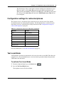
Redirection and call forward configuration
1
Configure the main office settings.
Configuration > Resources > Survivable Remote Gateway > S1000 Main Office Settings
tab
Internal Reference: CS 1000 information for the SRG on page 44
2
Configure the IP terminal settings.
Configuration > Resources > Survivable Remote Gateway > S1000 IP Terminal Details
tab
Internal Reference: IP telephones redirection on page 47
SRG50 Configuration Guide
32
Chapter 3 Task summary
NN40140-500
Chapter 4 CS 1000 considerations
33
Chapter 4
CS 1000 considerations
A Survivable Remote Gateway (SRG) extends CS 1000 features from the main office and provides
a business continuity solution to one or more remote SRG locations (branch offices).
The Main Office Configuration Guide for SRG50 (NN43001-307) provides information specific to
the configuration of an SRG50 on the CS 1000. This guide is included on the SRG50
documentation CD for your reference. Access to other CS 1000 documentation may be required if
personnel are not familiar with configuration of branch offices on the CS 1000.
The following activities are specific to SRG50 configuration when the main office call server is a
CS 1000:
•
•
•
•
•
•
•
•
•
•
“CS 1000 and SRG terminology comparison” on page 33
“Normal and local mode overview” on page 35
“Virtual trunk capacity” on page 38
“Vacant Number Routing (VNR)” on page 38
“Bandwidth management” on page 38
“Bandwidth management configuration: NBWM, ADBWM, and ACR” on page 40
“Emergency Services Access (ESA) configuration” on page 42
“CS 1000 information for the SRG” on page 44
“IP telephones redirection” on page 47
“Firmware upgrade” on page 51
CS 1000 and SRG terminology comparison
The table Comparison of CS 1000 and SRG terms and contexts on page 33 compares
configuration-related terms and contexts of the CS 1000 and the SRG.
Table 7 Comparison of CS 1000 and SRG terms and contexts (Sheet 1 of 2)
Term or Context
CS 1000
SRG
Dialing plan
on-net / off-net dialing
Private / Public network dialing
Type of number
CDP / UDP / GDP / TNDN
CDP / UDP / no equivalent
Numbers
TN (terminal number)
MOTN (main office terminal number)
TN = MOTN. That is, the TN from the main office is entered on the SRG in the
MOTN field (see “IP telephones redirection” on page 47).
BUID (branch user ID)
The dialable number of an IP telephone
at the SRG when it is called from a
phone located at the main office or
another branch office.
The CS 1000 BUID is entered on the
SRG (see S1000 IP Terminal Details
panel on page 48) but there is no SRG
equivalent for BUID.
SRG50 Configuration Guide
34
Chapter 4 CS 1000 considerations
Table 7 Comparison of CS 1000 and SRG terms and contexts (Sheet 2 of 2)
Term or Context
CS 1000
SRG
DN (directory number)
The dialable number of a telephone at
the main office when it is called from
another phone at the main office.
DN (directory number)
The dialable number of a telephone at
the SRG when it is called from another
phone at the SRG.
In the case of a CDP dialing plan, it is recommended that the BUID and the SRG
DN be the same.
In the case of a UDP dialing plan, the BUID has the form: <VOIP Trunk Access
Code> + <LOC> + <DN>. In this case, it is recommended that the SRG DN be
the same as <DN>.
The dialable number of an IP telephone at the SRG, when dialed from another
phone at the SRG, remains the same in both normal and local mode if the
preceding recommendations are implemented.
AC1
VOIP Trunk Access Code (see
CS 1000 information for the SRG on
page 44)
Destination code for VoIP trunks (see
Outgoing calls configuration on page
74)
AC1 = VOIP Trunk Access Code = Destination code for VoIP trunks
Routing
distant steering codes (DSC), trunk
steering codes (TSC), local steering
codes (LSC)
call routing, destination codes, line pool
access codes
digit manipulation table
dialout digits (routing)
Numbering Plan ID
ISDN/Telephony (E.164), Private,
Telephony (E.163), Telex (F.69), Data
(X.121), National Standard
Private
Access codes
(SRG: Destination codes)
7 = system trunk access
8 = Basic Alternate Route Selection
(BARS)/Network Alternate Route
Selection (NARS)
9 = public exchange access
7 = not assigned
8 = not assigned
Network Class of Service
Facility Restriction Level (FRL)
scheduled call routing
Network Bandwidth Management
Zone ID
9 = line pool A access code
Zone ID
Virtual Private Network ID (VPNI)
CS 1000 Zone ID = SRG Zone ID
ZDP = VPNI.
That is, the CS 1000 Zone ID is entered on the SRG in the Zone ID field, and the
ZDP is entered on the SRG in the VPNI field (see Bandwidth management on
page 38).
Trunks
public exchange
PSTN
IP telephone password
installer password
global password
The two passwords can be made the same. See Registration password on page
53.
NN40140-500
Chapter 4 CS 1000 considerations
35
Normal and local mode overview
Normal mode and local mode overview provides a description of the following sections:
•
•
•
•
•
“Normal mode” on page 35
“Local mode” on page 35
“Survivability” on page 36
“Recovery to normal mode” on page 37
“Testing the telephone in local mode” on page 37
Normal mode
IP Phones that are physically located at the SRG but are registered with the main office are
operating in normal mode. In normal mode, the main office provides centralized call processing to
all applications transparently to all IP Phones at the Branch Office.
Users of the SRG IP Phones receive the features, applications, key layout, and tones of the main
office Call Server. This provides feature and application transparency between the branch office
and the main office.
Local mode
Users at the branch office may be in local mode, or survivable mode for two different reasons:
1
IP Phone may have just booted up.
2
IP Phone cannot communicate to the main office because of a WAN failure or a failure of the
main office components.
Note: When a telephone or trunk in the main office calls an SRG IP Phone that
has switched to local mode due to WAN failure, the call is treated according to the
main office call redirection configuration (such as forwarding to voice mail or
continuous ringback).
In the event that the IP Phones at the branch office lose the connection to the main office CS1000
call server for any reason (WAN failure, main office call server failure, main office Signaling
Server failure), the SRG50 reverts to local mode automatically. Essentially, when VoIP
connectivity is lost, each IP Phone loses its Reliable UDP (RUDP) connection with the main office
terminal proxy server (TPS). The IP Phones at the branch office reboot and re-register to the
SRG50, placing them in local mode.
Once this has occurred, the IP Phones displays an indication on the display area that the set is in
local mode of operation. This display is configurable by installers to meet local language and
usage norms.
In local mode, the IP users connected at the branch office are under the control of the SRG50 call
services. As such, the normal main office call server features are not available. The SRG50 offers
a basic feature set when in local mode which allows IP Phones to continue to make and receive
calls internally within the branch office and over the provisioned local PSTN interfaces. Basic
SRG50 Configuration Guide
36
Chapter 4 CS 1000 considerations
services, such as transfer, last number redial, and single key access through the PSTN to a
centralized voice messaging system are supported. Local PSTN access and local Emergency
Services access is also supported. No local applications or Business Communication Manager
features are supported in local mode operation.
Analog devices continue to be under the control of the SRG50 system. It is the intent of local mode
to provide continued access to the PSTN for critical calls and emergency services.
In local mode, since the SRG50 handles all call processing, calls between two IP phones at the
SRG50 are handled locally as a simple station-to-station call. When an IP Phone initiates a local
PSTN call, the SRG50 routes the call to a trunk that is connected to the local PSTN. Incoming DID
calls are also handled by the SRG50 and terminated on the appropriate IP Phone.
In the event of a WAN failure, in local mode, the IP Phones do not have access to the main office
network over the VoIP trunks. If the appropriate alternate routes are configured, calls will be
routed to the main office or other branch offices using the available PSTN trunks.
While in local mode, the SRG50 system continues to monitor for a main office CS1000 heartbeat
signal, and once detected, automatically redirects phones on an individual basis back to normal
mode of operation. If a call is active, the SRG waits until the call is completed before redirecting
the phones; calls in progress are not interrupted. This redirection occurs almost immediately. This
reinstates the CS1000 normal user interface and feature set for the IP Phone user, on a user by user
basis.
The SRG50 system implements the same interface used by the MG1000B system to interact with
the main office CS1000 system. This allows the main office to identify attached clients and the
local PSTN as branch office entities, enabling proper operation of dial plans and E911 access.
In local mode, devices that are physically located at the branch office, that are controlled by the
local system and receive a basic telephony feature set, provide business continuity for the branch
office during the WAN or system failure. The SRG supports a main office heartbeat which
automatically reregisters users once WAN or system failure has recovered.
Survivability
SRG is specifically designed to provide automatic survivability against WAN failure, main office
Call Server failure, main office Signaling Server failure, and NRS (gatekeeper) failure.
SRG supports the Geographic Redundancy feature.
In the event of a WAN failure, the SRG IP Phones lose communication with the main office. This
causes the SRG IP Phones to reset and register with the SRG. The IP Phones then operate in local
mode, providing basic telephony services delivered by the local SRG system.
If the main office Call Server fails and call processing services are provided by an Alternate Call
Server, the SRG IP Phones reset and reregister with the Alternate Call Server and receive call
processing services from it. If no Alternate Call Server is available, the SRG IP Phones go to local
mode while the SRG attempts to find an Alternate Call Server by way of the network connection
server (NCS).
NN40140-500
Chapter 4 CS 1000 considerations
37
If the main office Signaling Server fails and an Alternate Signaling Server is available, the SRG IP
Phones reset and reregister with the SRG. The SRG will then query the NCS for the Alternate
Signaling Server’s IP address. The SRG will redirect the IP Phone to the Alternate Signaling
Server and continue to receive call processing services from the main office Call Server. If no
Alternate Signaling Server is available, the SRG IP Phones reset and register with the SRG in local
mode.
When an IP Phone at the SRG first boots up, the IP Phone attempts to communicate with the SRG.
After communication with the SRG is established, the SRG redirects the IP Phone to the main
office. When the SRG IP Phone attempts to register with the main office, the SRG first queries the
Primary NRS for the main office Virtual Trunk node IP address to redirect the IP Phone. If the
Primary NRS is down or unreachable, the SRG queries the Alternate NRS, if one is specified. If it
receives a positive response, the SRG IP Phone is redirected to the specified main office.
Otherwise, if neither a Primary or an Alternate NRS is available, the SRG IP Phone remains in
local mode, and receives call processing services from the SRG until communication can be
reestablished.
SRG IP Phones in normal mode remain registered with the main office if the Primary NRS fails
and no Alternate NRS is available. They can call any main office telephone or IP Phones in normal
mode in other branch offices.
SIP/ H323 trunks are used for Voice traffic alone. Proprietary TPSAR protocol is used for WAN
link health check and for Main Office TPS address discovery through NRS.
However, they cannot call any SRG analog (500/2500-type) telephones or any external numbers
through the SRG trunks because the Virtual Trunks are not available. (SRG analog [500/
2500-type] telephones are accessible if alternate routing is available through the PSTN.)
For more information about virtual trunks for SRG50, see the Main Office Configuration for
Survivable Remote Gateway 50 (NN43001-307).
Recovery to normal mode
Once communication is re-established with the main office call server, all IP Phones at the branch
office that are in local mode automatically redirect and reregister to the main office and return to
normal mode operation. IP Phones that were busy at the time communication was reestablished
complete the call in local mode, and then reregister with the main office after the call is complete.
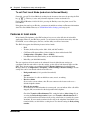
Testing the telephone in local mode
From normal mode, the branch user has the option of going to local mode manually using the Test
local mode feature. The test can be performed by the user at any time and does not require a
password. This test is invoked from any IP Phone at the branch office.
Nortel recommends testing local mode operation after changing the provisioning for a telephone
on the SRG.
To ensure that users do not forget to resume normal mode operation, the SRG redirects the
telephone to the main office to return the telephone to normal mode. This occurs if the telephone
remains registered to the SRG in test local mode for ten minutes (default setting). Alternatively,
the user can press the Quit key from the set to return to normal mode.
SRG50 Configuration Guide
38
Chapter 4 CS 1000 considerations
Virtual trunk capacity
The SRG supports a number of simultaneous calls depends on the specific codec type used.
SRG50 supports 24 virtual IP trunks that are either H.323 only, SIP only, or a combination of the
H.323 and SIP.
In normal mode, the codec selection used is controlled by specific programming of the CS1000. In
this case: SRG50 supports up to a maximum of 15 Virtual trunks unless both the intrazone and
interzone codecs are configured as Best Quality (G.711) in which case, the maximum number of
virtual trunks would be 24.
In local mode, if the WAN has failed, there are no longer any virtual trunks available between the
SRG50 and CS1000. However, the SRG50 will continue to convert calls from IP terminals for
communication via the PSTN. In this case, if G.711 is used (recommended), the number of
simultaneous calls from IP terminals to the PSTN supportable is a maximum of 24.
For more information about virtual trunks for SRG50, see the Main Office Configuration for
Survivable Remote Gateway 50 (NN43001-307).
Vacant Number Routing (VNR)
The SRG does not support Vacant Number Routing (VNR). Instead, the SRG uses Call Forward
All Calls to emulate VNR for the IP telephones that are in normal mode. Call Forward All Calls is
automatically cancelled when the phones revert to local mode.
A single destination code and route (or a group of destination codes and routes) can be configured
on the SRG to route all calls not terminated locally by the SRG. These calls are routed over the
VoIP trunks. If the VoIP trunks become unavailable, the calls are routed to the proper location
using PSTN fallback. This feature is similar to the VNR feature on the Media Gateway 1000B
(MG1000B).
Seamless dialing requires that the start digit of the DNs are unique for each system (coordinated
dialing plan). If the start digit is the same on both systems, the local users on the SRG must dial a
separate destination code before the main office DN.
For details about dialing plan and routing configuration, see Setting up the private VoIP network
on page 65.
Bandwidth management
Three levels of bandwidth management are supported by the CS 1000:
•
•
•
NN40140-500
Network Bandwidth Management (NBWM)
Adaptive Network Bandwidth Management (ADBWM)
Alternative Call Routing (ACR)
Chapter 4 CS 1000 considerations
39
Network Bandwidth Management (NBWM)
The SRG interoperates with the Network Bandwidth Management (NBWM) feature in a manner
similar to Media Gateway (MG) 1000B, though only G.711 and G.729 codecs are supported. At
the SRG, a Virtual Private Network ID (VPNI) and Zone ID are entered with values defined by the
main office configuration (see Bandwidth management configuration: NBWM, ADBWM, and
ACR on page 40). The VPNI and Zone ID allow the CS 1000 to recognize that H.323 and SIP calls
to and from the SRG are from a specific Bandwidth Management zone.
NBWM allows bandwidth zones to be configured on a network basis so that codec selection and
bandwidth allocation software can identify whether IP telephones or gateways are physically
collocated (in the same bandwidth zone) even though they are controlled by different call servers.
NBWM is used to define the codec selection policy and track bandwidth used for calls that
traverse the WAN (interzone calls) and the LAN (intrazone calls). The bulk of configuration for
NBWM is done at the main office.
Adaptive Network Bandwidth Management (ADBWM)
As with NBWM, only the VPNI and Zone ID are required at the SRG in order to implement he
Adaptive Network Bandwidth Management (ADBWM) feature on the SRG (see Bandwidth
management configuration: NBWM, ADBWM, and ACR on page 40).
ADBWM uses real-time interaction to enhance the performance of Voice over Internet Protocol
(VoIP) networks. ADBWM adjusts bandwidth limits and takes corrective action in response to
Quality of Service (QoS) feedback. This adjustment occurs dynamically, while calls are in
progress. A call server with ADBWM uses VPNIs and Zone IDs to keep track of the bandwidth
being used between its own zone and zones belonging to other call servers. If the interzone QoS
degrades below an acceptable level, the available bandwidth is reduced automatically between the
two zones. When the QoS between the two zones improves, the bandwidth limit is allowed to
return to normal.
Alternative Call Routing (ACR)
Configuration for Alternative Call Routing (ACR) at the SRG includes datafilling the Virtual
Private Network ID (VPNI) and Zone ID required by NBWM and ADBWM. However, additional
configuration is required and depends on the type of trunking provisioned at the main office:
Attendant service or DID trunks (see Bandwidth management configuration: NBWM, ADBWM,
and ACR on page 40).
ACR for NBWM allows a station-to-station call (that is, a call that does not use a trunk) to
overflow to traditional routes. Overflow can occur if there is insufficient interzone bandwidth
available to carry the call, or if the QoS has degraded to unacceptable levels. The feature applies to
station-to-station calls between a branch office and main office as well as from one branch office
to another branch office, provided both stations are registered to the same main office.
Network administrators who do not want calls to be blocked, yet have a limited amount of
bandwidth available, can use ACR to overflow calls to conventional trunks (PSTN or Tie/MCDN).
ACR allows calls to be routed by overflowing them, trading off the capital cost of WAN
bandwidth against the incremental cost of overflowed calls.
SRG50 Configuration Guide
40
Chapter 4 CS 1000 considerations
Bandwidth management configuration: NBWM, ADBWM, and
ACR
To configure SRG for NBWM and ADBWM
1
Obtain the Virtual Private Network ID and the Zone ID numbers configured at the main office.
2
Use Element Manager to enter these numbers in the appropriate fields at Configuration >
Telephony > Dialing Plan > Private Network > Dialing Plan - Private Network panel > VoIP
subpanel (see the figure Dialing Plan - Private Network panel, VoIP subpanel on page 40).
Figure 4 Dialing Plan - Private Network panel, VoIP subpanel
To configure Alternative Call Routing with attendant service
1
Complete the procedure, To configure SRG for NBWM and ADBWM on page 40.
For more information, see Outgoing calls configuration on page 74, and see also the
Networking Configuration Guide (NN40020-603).
2
Obtain the ALTPrefix for the SRG (configured at the main office).
NN40140-500
Chapter 4 CS 1000 considerations
3
4
41
Define a route to the main office Attendant over the PSTN.
a
Access the Dialing Plan - Routing panel (Configuration > Telephony > Dialing Plan >
Routing) and select the Routes tab.
b
Add a new route (for example, 997).
c
Ensure that the DN Type is Public (Unknown).
d
In the External Number field, enter the PSTN number of the main office Attendant
telephone.
e
Assign the PSTN line pool to the route (select the line pool from the Use Pool list; default
is A).
Add a destination code.
a
Access the Dialing Plan - Routing panel (Configuration > Telephony > Dialing Plan >
Routing) and select the Destination Codes tab.
b
Add a new destination code.
Use the ALTPrefix as the destination code.
c
In the ALTPrefix Destination Code row, select the Normal Route field.
d
Enter the route for the Attendant telephone (997).
e
In the adjacent Absorbed Length field, select All from the list.
When the SRG receives the ALTPrefix+DN digits from the main office, it looks up the destination
code table, finds a match for the ALTPrefix, dumps all the digits (ALTPrefix+DN), and dials the
main office Attendant.
To configure Alternative Call Routing with DID trunks
Note: In order to support DID trunks, the MODN dialed by an SRG
caller must match the DID digits.
Note: In the following procedure, it is assumed that the MODN matches
the XXXX portion of the DID’s NPA-NXX-XXXX; and that the
ALTPrefix is 3 digits.
1
Complete the procedure, To configure SRG for NBWM and ADBWM on page 40.
For more information, see Outgoing calls configuration on page 74 and the Networking
Configuration Guide (NN40020-603).
2
Obtain the ALTPrefix for the SRG (configured at the main office).
3
Define a route for the NPA-NXXX portion of the main office DID numbers.
a
Access the Dialing Plan - Routing panel (Configuration > Telephony > Dialing Plan >
Routing) and select the Routes tab.
b
Add a new route (for example, 996).
SRG50 Configuration Guide
42
Chapter 4 CS 1000 considerations
4
c
Ensure that the DN Type is Public (Unknown).
d
In the External Number field, enter the NPA-NXXX of the DID trunks that serve the
main office.
e
Assign the PSTN line pool to the route (select the line pool from the Use Pool list; default
is A).
Add a destination code.
a
Access the Dialing Plan - Routing panel (Configuration > Telephony > Dialing Plan >
Routing) and select the Destination Codes tab.
b
Add a new destination code.
Use the ALTPrefix as the destination code.
c
On the ALTPrefix Destination Code row, select the Normal Route field.
d
Enter the route for the route added above (996).
e
In the adjacent Absorbed Length field, select 3 from the list.
When the SRG receives the ALTPrefix+DN digits from the main office, it looks up the destination
code table, finds a match for the ALTPrefix, dumps the 3- digit ALTPrefix, appends the DN to the
External Number and dials the External Number+DN.
Emergency Services Access (ESA) configuration
The Main Office Configuration for Survivable Remote Gateway 50 (NN43001-307) guide covers
the procedures for configuring Emergency Services Access on both the SRG and the CS 1000. The
information here expands on the SRG procedure in that guide.
There are two methods of ESA support:
•
•
When a user dials 911, the telephone is redirected to the Branch Office and connects to
the SRG in local mode. The Main Office indicates the reason for redirection (as e911)
in the DRAM. The SRG dials 911 across the PSTN. The telephone remains in local
mode after the 911 call and is redirected to the Main Office after 10 minutes.
On-site notification for 911 — An external tool records an alarm when 911 calls are
made at the branch office. This is applicable to both telephones that are in local mode
due to the activation of a 911 call as well as locally connected analog sets. The
external tool connects to the SRG through LAN CTE.
Note: This procedure applies only to redirected IP telephones when the
SRG is in normal mode.
For IP telephones in local mode, and for other telephones at the SRG, see
the Networking Configuration Guide (NN40020-603) for configuring
emergency services.
NN40140-500
Chapter 4 CS 1000 considerations
43
To configure Emergency Services Access
1
Verify that a remote access package has been assigned to the VoIP trunks (see Remote Access
Package for VoIP trunks on page 76).
2
Obtain the ESA Special Number (SPN).
3
In Element Manager, access the Dialing Plan - Routing panel (Configuration > Telephony >
Dialing Plan > Routing) and click the Destination Codes tab.
4
Add a destination code corresponding to the ESA SPN for the SRG branch office.
5
In the Destination Codes table, click the Absorbed Length field of the ESA SPN destination
code. The numbers indicate the number of digits the SRG absorbs, from left to right.
6
Select the number of digits to absorb so that just the Emergency Services DN (ESDN)
remains.
7
In the Destination Codes table, click the Normal Route field of the ESA SPN destination
code. Enter a public route to the PSTN trunks.
In
Note: The Normal Route field defaults to 000. Route 000 (click the
Routes tab) is preconfigured to Use Pool A and cannot be changed. Pool
A is preconfigured for PSTN trunks in the default state. Hence, if the
default state of Pool A has not been changed, leave the Normal Route
field as 000.
To check the state of Pool A, navigate to Configuration > Lines >
Active Physical Lines. Pool A must be assigned to at least one Trunk
Type that provides access to the PSTN.
Do not configure Alternate Routes.
8
Navigate to the Dialing Plan - Public Network panel (Configuration > Dialing Plan > Public
Network).
9
In the Public Network DN Lengths subpanel, verify that there is a DN Prefix of 911 with a
DN Length of 3.
If not, add the 911 DN Prefix. If required, double click the DN Length field and then change
the value to 3.
To configure on-site notification
To use the on-site notification for Emergency Services, you need to include a LAN CTE port
in your keycode.
SRG50 Configuration Guide
44
Chapter 4 CS 1000 considerations
CS 1000 information for the SRG
In order to redirect IP telephones and forward calls to the main office (Call Forward All Calls
feature), the SRG requires information about the main office network environment. This
information is recorded through Element Manager on the S1000 Main Office Settings panel.
S1000 Main Office Settings panel
The table S1000 Main Office Settings on page 44 lists and describes each field of the S1000 Main
Office Settings panel. Record the actual value in the Values column to facilitate configuration and
provide a record of the datafill.
Table 8 S1000 Main Office Settings (Sheet 1 of 3)
Field
Values
Description
Primary Network
Connect Server Address
<ip address>
IP address of the primary NCS.
Alternate Network
Connector Server
Address
<ip address>
IP address of the alternate NCS, if deployed. If not,
enter the same address as for Primary Network
Connect Server Address.
Network Connect Server
Port
16500 (default)
Port on the SRG used to connect to the NCS.
Range: 0 to 65535
Heartbeat Protocol Port
16501 (default)
Range: 0 to 65535
Port on the SRG that the SRG uses to monitor the
status of the connection with the main office
terminal proxy server (that is, to confirm
connectivity with the main office)
VOIP Trunk Access Code
Access code for the main office VoIP trunk.
Required for UDP dialing plan only. Ignored for
CDP dialing plan, field can be left blank.
VOIP Trunk Access Code = Destination code for
VoIP trunks* = AC1**
* Destination code for VoIP trunks is entered during
configuration for advanced routing. see “Outgoing
calls configuration” on page 74.
** For a UDP dialing plan, AC1 is the access code
in the digit string <AC1> <LOC> <DN>
Test Local Mode Timeout 10 minutes (default)
Period that an IP telephone remains in local mode
after being set in local mode manually. Telephone
returns to normal mode automatically at the end of
the time-out.
Range:
2 to 10 minutes
Local mode can be invoked by the Test Local Mode
button on the telephone or by command from the
main office.
NN40140-500
Chapter 4 CS 1000 considerations
45
Table 8 S1000 Main Office Settings (Sheet 2 of 3)
Field
Values
Description
H323 ID
SRG* (default)
*This setting must be changed.
Gatekeeper setting that identifies the SRG.
see the Networking Configuration
Guide (NN40020-603) for naming
conventions.
Numbering Plan ID
Unknown
ISDN/Telephony (E.164)
Private
Telephony (E.163)
Telex (F.69)
Data (X.121)
National Standard
This value must match the value in the Alias
names field of the Local IP gateway:
Configuration > Resources > Telephony
Resources > Modules panel > Module type
column: select IP Trunks > Details for Module:
Internal details panel > Local Gateway tab >
Gatekeeper Support subpanel > Alias names
field (see VoIP trunking configuration on page 72).
The SRG acts as a SIP endpoint and obtains the
Main Office TPS IP address from the NCS using
the H323 ID.
Configure this field as the same SIP endpoint name
as you configure for the NRS endpoint name. This
is a generic field used for both SIP and H.323
virtual trunk configurations.
The type of numbering plan at the main office.
Default: Private
Type of Number
Unknown
International Number
National Number
Special Number
Subscriber Number
ESN LOC (UDP)
ESN CDP
ESN Special Number
The main office dialing plan.
Ensure that the SRG private dialing plan is
configured to match the selected value.
Default: ESN CDP (for CDP dialing
plans) (BUID = DN)
UDP dialing plans: select ESN
LOC (UDP) (BUID = LOC+DN)
SRG50 Configuration Guide
46
Chapter 4 CS 1000 considerations
Table 8 S1000 Main Office Settings (Sheet 3 of 3)
Field
Values
Description
Node ID
9999 (default)
Automatically written to the IP telephone firmware
when the IP telephone registers with the main
office.
Used to identify the node on the main office
associated with the IP telephone DN.
Range: 0 to 9999
MO Access Code Length
For CDP dialing plans: set to 0
For UDP dialing plans: set to
length of line pool access code or
destination code in front of LOC.
The number of digits to add to the BUID (DN) so
the main office system can determine if the
incoming call is valid.
Range: 0 to 34
To datafill the S1000 Main Office Settings panel
1
In Element Manager, navigate to Configuration > Resources > Survivable Remote Gateway
(see the figure S1000 Main Office Settings panel on page 46).
2
Select the S1000 Main Office Settings tab.
3
Enter the information in the appropriate fields.
Figure 5 S1000 Main Office Settings panel
NN40140-500
Chapter 4 CS 1000 considerations
47
IP telephones redirection
Once an IP telephone at the SRG is configured (see IP telephones setup and configuration on page
53), it automatically registers with the SRG (S1). To configure an IP telephone for redirection to
the main office call server, SRG-specific datafill is required. The SRG-specific configuration
includes:
•
•
IP telephones numbers and models on page 47
S1000 IP Terminal Details panel on page 48
To configure SRG using SIP trunks, CS1K must accept the end point as an H323 and SIP entity
and accept it as h323 and SIP endpoint. You do not need to enter BCM SRG50 configuration
under Telephony Resources > IP Trunks > H323 Setting. The entire configuration for SIP trunking
must be entered under SIP settings, SIP Proxy, SIP media parameters, SIP URI Maps and SIP
Authentication.
IP telephones numbers and models
SRG DNs are assigned to IP telephones using Element Manager. Redirection to the main office
requires configuration at the SRG to associate the SRG DN with the CS 1000 terminal number
(TN) and the corresponding branch user ID (BUID).
When the CS1000 TN is configured, the IP telephone model forms part of the record. At the SRG,
the actual IP telephone configured to an SRG DN must be the same model that is configured in the
TN record that is associated with the SRG DN.
The table IP telephone numbers and models on page 47 provides a record of the CS 1000 TN and
BUID, the SRG MOTN and DN, and the model of phone, to facilitate installation and provide a
permanent record of the configuration.
Table 9 IP telephone numbers and models (Sheet 1 of 2)
TN (CS 1000)
MOTN (SRG)
(same number)
BUID (same
number at CS 1000
and SRG)
SRG DN
IP telephone model
SRG50 Configuration Guide
48
Chapter 4 CS 1000 considerations
Table 9 IP telephone numbers and models (Sheet 2 of 2)
TN (CS 1000)
MOTN (SRG)
(same number)
BUID (same
number at CS 1000
and SRG)
SRG DN
IP telephone model
S1000 IP Terminal Details panel
Element Manager provides SRG-specific panels for recording the CS 1000 TN and BUID that are
associated with a particular SRG DN. The table SRG S1000 IP Terminal Details fields on page 48
lists and describes the fields on the S1000 IP Terminal Details panel.
Table 10 SRG S1000 IP Terminal Details fields (Sheet 1 of 2)
Field
Values
Description
DN
Read-only
The SRG DN assigned to the telephone.
The SRG DN must be configured before proceeding with the
procedures that follow in this section. See Telephone (DN) records
configuration on page 56.
Hardware
ID
Read-only
Hardware ID.
Unique for each IP telephone.
Status
Read-only
Current status of the telephone.
See IP terminal details on page 84 (expand the field to read the entire
status message).
NN40140-500
Chapter 4 CS 1000 considerations
49
Table 10 SRG S1000 IP Terminal Details fields (Sheet 2 of 2)
Field
Values
Description
Firmware
Version
Read-only
Updated by the main office when a terminal is sent back to the SRG for
firmware upgrade purposes. The field specifies the firmware version
required by the main office.
MOTN
XXX
Required for telephone redirection.
The field is the main office TN associated with the IP telephone.
BUID
CDP network: <DN>
Required for telephone redirection.
The field represents the dialable number of an IP telephone at the SRG
UDP network: <VoIP access when it is called from a phone located at the main office or another
branch office.
code> + <LOC> + <DN>
The BUID at the SRG must be the same as the BUID at the main office.
MO TPS
Read-only
This field echoes the address of the main office terminal proxy server
when the IP telephone is redirected.
Note: The SRG DNs must be configured before the following
procedures can be undertaken. See Telephone (DN) records
configuration on page 56.
To enter the MOTN and BUID
1
In Element Manager, navigate to Configuration > Resources > Survivable Remote
Gateway.
2
Select the S1000 IP Terminal Details tab (see the figure S1000 IP Terminal Details panel on
page 50).
3
Refer to the numbers and models recorded in the table IP telephone numbers and models on
page 47.
4
Select the required DN.
5
Press the Modify button.
6
Enter the MOTN and the BUID in the appropriate fields.
To redirect the telephone to the main office call server
1
In Element Manager, navigate to Configuration > Resources > Survivable Remote
Gateway.
2
Select the S1000 IP Terminal Details tab (see the figure S1000 IP Terminal Details panel on
page 50).
3
Select the DN of the telephone to be redirected.
4
Press the Redirect Set button.
SRG50 Configuration Guide
50
Chapter 4 CS 1000 considerations
Figure 6 S1000 IP Terminal Details panel
IP telephone settings
For IP telephones that are redirected to the main office call server, incorporate the settings shown
in the table Configuration settings for redirected IP Phones on page 50. The Device Configuration
Guide (NN40020-300) and the Networking Configuration Guide (NN40020-603) provide detailed
instructions for configuring IP telephones.
Table 11 Configuration settings for redirected IP Phones
Parameter
Setting
S1 IP
SRG IP address
S1 Port
7300
S1 Action
1
S1 Retry Count
1
S2 IP
SRG IP address
S2 Port
7300
S2 Action
1
S2 Retry Count
1
NN40140-500
Chapter 4 CS 1000 considerations
51
Firmware upgrade
The redirected IP telephones at the SRG are under the control of the main office call server for the
majority of their deployment and receive all of their features in that context. Therefore, the version
of IP set firmware must align with the requirements of the CS 1000.
Supported firmware
The table Supported IP clients and firmware versions on page 51 lists the IP clients and related
firmware versions supported on the SRG50. The SRG50 column indicates the firmware versions
included with the SRG software. The CS 1000 columns identify the version of firmware to use for
specific releases.
Table 12 Supported IP clients and firmware versions
IP Client
SRG50
CS 1000
Release 4.0
Release 4.5
Release 5.0
Phase I: 2002, 2004
B65 or greater
B65 or greater
B76 or greater
B76 or greater
Phase II: 2001, 2002,
2004
D98 or greater
D88 or greater
0604DBG or
0604DAS
0604DBG
IP Phone 2007
C22 or greater
C22 or greater
0621C4J or 0621C3J
0621C4J
WLAN Handsets 2210/
2211
Not embedded in
SRG software
Use the 2210/2211
GA firmware load.
97.059 or greater
97.059 or greater
WLAN Handset 2212
Not embedded in
SRG software
97.039 or greater
97.059 or greater
97.059 or greater
WLAN Handsets 6140/
6120
Not embedded in
SRG software
WLAN Handsets 1210/
1220/1230
062AC57
IP Phone 2033
Not embedded in
SRG software
S12 or greater
S12 or greater
S12 or greater
IP Phone 1110
0623C38
0624C1E
0623C4B or 0623C3C 0623C4D
IP Phone 1120E
0624C1B
0624C1E
0624C4B or 0624C3C 0624C4D
IP Phone 1140E
0625C1B
0625C1E
0625C4B or 0625C3C 0625C4D
IP Softphone 2050
build 385 or greater build 385 or greater
build 385 or greater
2.1.355 or greater
MVC 2050
build 126 or greater build 126 or greater
build 126 or greater
2.1.202 or greater
Firmware upgrade procedure
When an IP telephone requires a firmware upgrade, the CS 1000 uses the umsUpgradeAll
command, or variant, to redirect the telephone back to the SRG for upgrading. If the required file
does not exist on the SRG, or its version is incorrect, the SRG initiates an FTP session to the TPS
for that phone to retrieve the required file. The SRG upgrades the phone and redirects it back to the
CS 1000. After the SRG receives new firmware from the Main Office for a specific IP telephone,
all the IP telephones of the same type are loaded with the new firmware.
SRG50 Configuration Guide
52
Chapter 4 CS 1000 considerations
NN40140-500
53
Chapter 5
IP telephones setup and configuration
IP telephone setup and DN configuration are described in detail in the IP Telephone Installation
and Configuration Guide and the Networking Configuration Guide (NN40020-603), respectively.
SRG-specific procedures and settings include:
•
•
•
•
•
•
•
•
•
•
•
Registration password on page 53
Local mode indication on page 55
IP telephone codec and jitter settings on page 55
Telephone (DN) records configuration on page 56
Received numbers configuration on page 59
DHCP settings configuration on page 60
Call forwarding options on page 60
Configuration settings for redirected phones on page 61
Test Local Mode on page 61
Features in local mode on page 62
911 Emergency Services Support on page 63
Registration password
If a registration password is configured on the SRG, the IP telephone installer must enter the
password before the telephone can be configured.
To set the IP telephone registration password
1
In Element Manager, navigate to Configuration > Resources > Telephony Resources.
2
On the Modules panel, locate the Module type column and select the IP & Application Sets
row (see the figure Telephony Resources panel, IP and App Sets on page 54).
3
On the Details for Module: subpanel, select the IP Terminal Global Settings tab.
SRG50 Configuration Guide
54
Chapter 5 IP telephones setup and configuration
There are three fields that define the password registration process (see the table Password
registration parameters on page 54):
Enable registration, Enable global registration password, and Global password.
Table 13 Password registration parameters
Enable registration
Must be selected to allow IP telephones to register.
Enable global registration
password
Select if a password is going to be entered in the next
field, Global password.
If selected, the installer must enter the Global password
(below) at the IP telephone before the telephone can be
configured.
Global password
Enter the password.
If no password is entered, or the Enable global
registration password is not selected, no password is
required to configure the IP telephone.
Note: Nortel recommends that you synchronize this
password with the CS 1000 password.
Figure 7 Telephony Resources panel, IP and App Sets
4
Select and enter the values to meet the password requirements of your installation.
5
Set the Auto-assign DNs check box according to the requirements of your installation (if set,
the SRG automatically assigns DNs, see the Device Configuration Guide (NN40020-300) for
details).
NN40140-500
Chapter 5 IP telephones setup and configuration
55
Local mode indication
When an IP telephone is in local mode, a message is displayed on the phone to indicate the local
mode state to the user. The default setting is Local Mode.
To change local mode indication
1
In Element Manager, navigate to Configuration > Resources > Telephony Resources.
2
On the Modules panel, locate the Module type column and select the IP Sets row (see the
figure Telephony Resources panel, IP and App Sets on page 54).
3
On the Details for Module subpanel, select the IP Terminal Global Settings tab.
4
The Advertisement/Logo field specifies the message that provides local mode indication.
Change as required.
IP telephone codec and jitter settings
When the IP telephones are operating in local mode, codec and jitter settings are set on a
phone-by-phone basis. Configure the settings to meet the requirements of the local SRG
environment. They do not have to be the same as the main office settings (in contrast to the QoS
settings for the VoIP trunks; see QoS settings (codec, jitter buffer, and related items) on page 70).
To enter codec and jitter settings for IP telephones in local mode
1
In Element Manager, navigate to Configuration > Resources > Telephony Resources.
2
On the Modules panel, locate the Module type column and select the IP Sets row (see the
figure Modules panel, IP & Application Sets on page 56).
3
On the Details for Module subpanel, select the IP Terminal Global Settings tab.
The fields related to QoS are on the right side of the panel.
4
Enter the appropriate values.
SRG50 Configuration Guide
56
Chapter 5 IP telephones setup and configuration
Figure 8 Modules panel, IP & Application Sets
Telephone (DN) records configuration
DN records for IP telephones are configured through the All DNs panel (Configuration >
Telephony > Sets > All DNs (see the figure All DNs panel on page 58). The Networking
Configuration Guide (NN40020-603) and the Device Configuration Guide (NN40020-300)
provide basic instructions for configuring DNs and IP telephones. The following instructions are in
addition to these instructions and only apply to IP telephones that are to be redirected to a main
office call server.
Note: It is assumed that the line pools have been assigned. In the default
configuration, VoIP trunks are assigned to line pool BlocA and the four
PSTN trunks are assigned to line pool A. For more information, see
SRG50 overview on page 15.
To configure DN records for redirected IP telephones
1
In Element Manager, navigate to the All DNs panel (Configuration > Telephony > Sets > All
DNs).
2
Select the Line Access tab.
3
Identify the row of the DN record to be configured.
4
Refer to the list of numbers and phone models recorded in the table (see CS 1000
considerations on page 33).
NN40140-500
Chapter 5 IP telephones setup and configuration
5
57
From the Model list, select the model of telephone assigned to this DN.
For CS 1000: See IP telephones numbers and models on page 47.
6
To support outgoing caller ID over the VoIP trunk, the Private OLI field (Priv. OLI) must be
set to the DN.
7
To support outgoing number display over the PSTN, enter the public access number for the
telephone in the Public OLI field (Pub. OLI).
8
Leave the Fwd All field blank to disable the Call Forward All Calls feature when the telephone
is in local mode. In normal mode, the SRG can forward all calls to the main office call server
automatically (see Call forwarding options on page 60). In local mode, the Call Forward All
Calls feature is automatically discontinued and the SRG routes calls to the SRG DNs.
Call Forward All Calls does not require Allow redirect to be enabled (Allow redirect
is found on the Capabilities tab of the Details for DN subpanel when the
Capabilities and Preferences tab is selected).
9
To assign specific PSTN lines to each telephone, add the line(s) (Details for DN details panel
> Line Assignment tab). You would do this if, for example, you want one user to field all
customer calls when the system is in local mode (see the figure All DNs panel on page 58).
10 Ensure that the Appearance Type (Details for DN details panel > Line Assignment tab) is
set to Ring only.
11 Assign the VoIP and PSTN trunk line pools to the DN (Details for DN details panel > Line
Pool Access tab).
12 Assign a target line to the DN (Details for DN details panel > Line Pool Access tab). For a
description of target lines, see SRG50 terminology on page 20.
Note: At this point, you may want to configure the received numbers.
Refer to Received numbers configuration on page 59 and then return to
this procedure.
SRG50 Configuration Guide
58
Chapter 5 IP telephones setup and configuration
Figure 9 All DNs panel
13 Select the Capabilities and Preferences tab.
14 In the Intercom keys column, set Intercom Keys to 1 if required.
15 On the Details for DN subpanel, select the Button Programing Table tab.
16 Program the voice mail access button with the PSTN dialup for the main office voice message
system.
NN40140-500
Model
Button
2001
Message
2002
06
2004
08
2007
08
2033
08
2050, 2050CE
08
2210
08
2211
08
2212
08
1110
08
1120E
08
1140E
08
Chapter 5 IP telephones setup and configuration
59
Received numbers configuration
The Public Received number length and the Private Received number length (see Basic
parameters on page 67) determine the number of digits that the SRG retains for call processing.
The retained digits are mapped to the DN using fields provided on the Target Lines panel. (For
more information on target lines, see SRG50 terminology on page 20).
Note: If the retained digits are the same as the DN, the fields (Pub.
Received # field and Priv. Received # field) can be left blank.
To map received numbers to the DN
1
In Element Manager, navigate to Configuration > Telephony > Lines > Target Lines (see
the figure Target Lines panel on page 59).
2
Select the target line of the DN for which you want to configure the received numbers.
3
Double-click the Pub. Received # field, and then enter the retained received digits for calls
originating from the PSTN.
4
Double-click the Priv. Received # field, and then enter the retained received digits for calls
originating from the private network (that is, the VoIP trunks). This number is usually the same
as the DN.
Figure 10 Target Lines panel
SRG50 Configuration Guide
60
Chapter 5 IP telephones setup and configuration
DHCP settings configuration
To configure DHCP settings for SRG operation
1
In Element Manager, navigate to Configuration > Data Services > DHCP Server.
2
Select the General Settings tab.
3
From the DHCP Server is list, select Enabled - IP Phones Only.
4
From the WINS node type list, select H-node.
5
In the Default gateway field, enter an address that meets the requirements of the SRG50 LAN.
6
In the Lease time field, enter a value that meets the requirements of your system.
Leave all other fields under the General Settings tab blank.
7
Select the IP Terminal DHCP Options tab.
8
On the Primary Terminal Proxy Server (S1) and Secondary Terminal Proxy Server (S2)
subpanels:
9
a
In the IP address field, enter the IP address of the SRG.
b
From the Port list, select SRG.
c
In the Retry count field, enter the number of retries that the IP telephone is allowed to
connect to the SRG before an event is generated (see IP terminal details on page 84).
Select the Address Ranges tab and add a range of IP address to meet the requirements of your
system.
Call forwarding options
There are two options for configuring call forwarding on the SRG:
•
The target DN is determined by the BUID/MODN and VoIP Trunk access codes.
In this case, the information required for call forwarding is entered using the
SRG-specific panels of Element Manager (Configuration > Resources > Survivable
Remote Gateway). For more information, see CS 1000 considerations on page 33.
Note: Call forwarding is mandatory for CS 1000.
•
The target DN is configured explicitly for each IP telephone.
The DN is configured through Element Manager on the Telephony > Sets > Active
Sets panel using the standard BCM50 procedure. Typically, the call forward number
is the BUID. For more details, see the Device Configuration Guide (NN40020-300).
NN40140-500
Chapter 5 IP telephones setup and configuration
61
The disadvantage of the second option is that the installer must configure the target
DN in two places: on the Active Sets panel and on the SRG-specific panels (the
SRG-specific panels must be completed). The SRG looks at the SRG-specific panels
first. It goes to the Active Sets panel only if the VOIP Trunk Access Code has not
been configured.
Configuration settings for redirected phones
The Telephony Device Installation Guide and the Networking Configuration Guide provide
detailed instructions for configuring IP telephones. For IP telephones that are redirected to the
main office call server, incorporate the settings shown in the table Configuration settings for
redirected IP telephones on page 61.
Table 14 Configuration settings for redirected IP telephones
Parameter
CS 1000
S1 IP
SRG IP address
S1 Port
7300
S1 Action
1
S1 Retry Count
1
S2 IP
SRG IP address
S2 Port
7300
S2 Action
1
S2 Retry Count
1
For more information, see CS 1000 considerations on page 33.
Test Local Mode
An IP telephone operating in normal mode can be forced to redirect to the SRG. This allows the
telephone user, and system administrator, to test local mode operation without taking down the
VoIP trunk to the main office.
To activate Test Local Mode
1
From the telephone dialpad, press the Services key
2
Press the Test Local Mode button.
.
The telephone is now in Test Local Mode.
SRG50 Configuration Guide
62
Chapter 5 IP telephones setup and configuration
To exit Test Local Mode (and return to Normal Mode)
Generally, you exit Test Local Mode by waiting for the feature to time out or by pressing the Exit
key (
). This key is active only when the telephone is in the local mode test.
For the WLAN Handsets 2210/2211/2212, pressing the End key causes the phone to exit Test
Local Mode.
If the phone does not have an Exit key, you must wait until the test times out For more information
about Test Local Mode Timeout, see S1000 Main Office Settings panel on page 44.
Features in local mode
In local mode, IP telephones at the SRG no longer have access to the full suite of main office
applications. However, the SRG does provide a set of features that include connectivity with the
local PSTN, access to Emergency Services, and the ability to call local extensions.
The SRG also supports the following features in local mode:
•
•
•
•
•
Hold
Transfer (dedicated key on the 2002, 2004, and 2007 models)
Call Forward No Answer/Busy (if the feature has been enabled on the DN:
Configuration > Telephony > Sets > All DNs)
Last Number Redial (dedicated key on the 2002/2004 models)
Inbox Key (on 2002/2004 models)
The user experience in local mode can be enhanced if certain global feature settings are
coordinated with the main office so that the settings are the same at both the main office and the
SRG. These feature settings are configured with the Feature Settings panel on the Element
Manager interface (Configuration > Telephony > Global settings > Feature Settings). Feature
settings that can be coordinated with the main office are:
•
•
•
•
Background music (if it is provided for on-hold)
On-hold
This determines if a caller on hold hears tones, music, or nothing.
Receiver volume
Set to use the system volume, since IP users cannot use the feature code to set a
default telephone volume.
Delayed ring transfer
If a transfer to an external number is not answered, you can indicate if the call will be
dropped (Off) or transferred to the designated Prime telephone.
Check the Transfer callback timeout. This setting defaults to After 4 rings. If you
are using the Delayed ring transfer feature, turn Transfer callback timeout off if
you want all unanswered transferred calls to ring at the Prime set (usually the system
attendant). If you want the transferred call to ring at the telephone from which it was
transferred first, set this field to a setting that is less than the setting for Delayed ring
transfer.
NN40140-500
Chapter 5 IP telephones setup and configuration
•
•
•
63
Held line reminder
If set to a time, determines period between when a call is put on hold and when a short
tone sounds at the telephone to indicate the call is still on hold.
Alarm set
The alarm set feature is not supported on SRG.
Language and Contrast
Language and Contrast are DN-specific settings and are configured at Configuration
> Telephony > Sets > All DNs > All DNs panel > Capabilities and Preferences tab
> Details for DN subpanel > Preferences tab.
Features not supported in local mode include: Hot Desking, Do Not Disturb, Page, Call Forward,
Background Music, Call Park, Call Pickup, Speed Dial, and Conference.
911 Emergency Services Support
For IP telephones in local mode, and for other telephones at the SRG, the Networking
Configuration Guide (NN40020-603) provides details for configuration of 911 emergency
services.
For redirected IP telephones in normal mode, the IP telephone is registered with the main office
call server. Ensure that the main office call server is configured so that a 911 call from an IP
telephone at the SRG is routed back to the SRG’s local PSTN. Emergency Services Access (ESA)
configuration on page 42 includes a procedure for configuring the SRG for CS 1000 Emergency
Services Access.
SRG50 Configuration Guide
64
Chapter 5 IP telephones setup and configuration
NN40140-500
65
Chapter 6
Setting up the private VoIP network
To provide SRG functionality and to take advantage of VoIP technology, a private VoIP network
is required between the SRG and the main office. This chapter details the procedures for
establishing appropriate WAN connections to enable a VoIP network between the main office and
SRG branch locations. Before proceeding, ensure that IP networking from the SRG to the WAN,
and from the main office call server to the WAN have been configured and tested (see the figure IP
networking, SRG to WAN, main office to WAN on page 65). SRG-specific configuration
establishes the VoIP network (see the figure VoIP path for SRG operation on page 66).
Figure 11 IP networking, SRG to WAN, main office to WAN
Main office
Branch office
SRG
IP phones
IP phones
IP network connections
WLAN
handsets
Software
phones
IP Networking
SRG50 Configuration Guide
66
Chapter 6 Setting up the private VoIP network
Figure 12 VoIP path for SRG operation
Main office
Branch office
SRG
IP phones
IP phones
IP network connections
WLAN
handsets
Software
phones
VoIP trunks
IP Networking + VoIP trunks
Generic procedures for setting up a private network on the SRG are covered in the Networking
Configuration Guide (NN40020-603). Items to address when establishing the private VoIP
network between the SRG and the main office are:
•
•
•
•
•
•
•
•
•
•
•
•
NN40140-500
Basic parameters on page 67
Private dialing plan on page 68
Meridian Customer Defined Network (MCDN) on page 69
QoS settings (codec, jitter buffer, and related items) on page 70
Network security on page 72
VoIP trunking configuration on page 72
Line pools on page 74
Call routing on page 74
Outgoing calls configuration on page 74
SRG PSTN access on page 76
Main office information on page 78
External attendant support on page 78
Chapter 6 Setting up the private VoIP network
67
Basic parameters
The table Basic parameters on page 67 provides a record of basic parameters that are significant
for SRG operation. Typically, these parameters are specified as part of BCM50 foundation
activities; in most cases, their configuration is not covered in the SRG50 Configuration Guide.
Table 15 Basic parameters (Sheet 1 of 2)
Parameter
DN length
Value
Context
Configured as part of BCM50 foundation configuration.
There are four DN lengths to consider.
1. Configuration > Telephony > Dialing Plan > General > Dialing
Plan - General panel > Global Settings subpanel > DN length
(intercom) field
This is the internal DN length. That is, the length of DNs for calls
between telephones on the SRG.
2. Configuration > Telephony > Dialing Plan > Public Network >
Dialing Plan - Public Network panel> Public Network Settings
subpanel > Public Received number length field
For calls originating from the PSTN, this establishes the number of
digits the SRG retains.
3. Configuration > Telephony > Dialing Plan > Private
Network > Dialing Plan - Private Network panel > Private
Network Settings subpanel > Private Received number length field
For calls originating from a private network, this establishes the
number of digits the SRG retains.
4. Configuration > Telephony > Dialing Plan > Private
Network > Dialing Plan - Private Network panel > Private
Network Settings subpanel > Private DN length field
Used for DPNSS applications only. See the Networking
Configuration Guide (NN40020-603).
DN range
Configured as part of BCM50 foundation configuration.
DN range of the SRG is set by the hardware configuration and
keycodes. Actual numbering is contiguous from the Start DN:
Administration > Utilities > Reset > Reset panel > Cold Reset
Telephony Services button > Cold Reset Telephony dialog box >
Start DN field
Destination code
for VoIP trunks
Configured for advanced routing. See Outgoing calls configuration
on page 74
VoIP destination code = VOIP Trunk Access Code* = AC1**
* VOIP Trunk Access Code is entered on the main office settings
panel. See the server-specific chapters for details.
** For a UDP dialing plan, AC1 is the access code in the digit string
<AC1> <LOC> <DN>.
SRG IP address
Configured as part of BCM50 foundation configuration.
Configuration > System > IP Subsystem > IP Subsystem panel >
General Settings tab > IP Settings details subpanel
SRG50 Configuration Guide
68
Chapter 6 Setting up the private VoIP network
Table 15 Basic parameters (Sheet 2 of 2)
Parameter
Value
Context
SRG net mask
Configured as part of BCM50 foundation configuration.
Configuration > System > IP Subsystem > IP Subsystem panel >
General Settings tab > IP Settings details subpanel
IP address of
SRG gateway
Configured as part of BCM50 foundation configuration.
Configuration > System > IP Subsystem > IP Subsystem panel >
General Settings tab > IP Settings details subpanel
VLAN
If the SRG operates as part of a VLAN, obtain the required
identifiers from the VLAN administrator.
Configuration > Data Services > DHCP Server > DHCPServer
panel > IP Terminal DHCP Options tab > VLAN Identifiers subpanel
PSTN number for
dialing into the
main office from
the SRG when in
local mode
Required to specify a PSTN fallback route. See Outgoing calls
configuration on page 74.
PSTN number for
dialing into the
SRG from the
main office when
in local mode
Required for main office configuration.
Private dialing plan
For SRG operation, either a coordinated dialing plan (CDP) or a uniform dialing plan (UDP) can
be configured. Nortel recommends CDP because it requires the least dialing manipulation between
the SRG and the main office call server. The dialing plan choice also determines whether the DN
on the SRG matches the BUID.
Dialing plans between the SRG and the main office call server must be compatible. Private dialing
plan configuration is described in detail in the Networking Configuration Guide (NN40020-603).
The type of dialing plan, CDP or UDP, is determined by the main office configuration.
The path to the Element Manager panel for setting up the dialing plan is Configuration >
Telephony > Dialing Plan > Private Network > Dialing Plan - Private Network panel > Private
Network Settings subpanel (see the figure Dialing Plan — Private Network panel, Private Network
Settings subpanel on page 69).
NN40140-500
Chapter 6 Setting up the private VoIP network
69
Figure 13 Dialing Plan — Private Network panel, Private Network Settings subpanel
Meridian Customer Defined Network (MCDN)
MCDN is automatically activated when the system is converted to SRG operation. To ensure that
redirected IP telephones can transfer calls to the SRG local telephones, trunk anti-tromboning
(TAT) must be enabled.
To enable MCDN TAT
Use Element Manager to enable TAT by selecting the TAT checkbox at Configuration >
Telephony > Dialing Plan > Private Network > Dialing Plan - Private Network panel > MCDN
subpanel (see the figure Dialing Plan — Private Network panel, MCDN subpanel on page 70).
SRG50 Configuration Guide
70
Chapter 6 Setting up the private VoIP network
Figure 14 Dialing Plan — Private Network panel, MCDN subpanel
QoS settings (codec, jitter buffer, and related items)
Quality of Service (QoS) settings for the VoIP trunks at the SRG are determined by the main office
settings; the SRG settings must match the main office. Use the table Main office QoS settings on
page 70 to record the main office settings, to facilitate configuration, and to provide a record of the
datafill.
Table 16 Main office QoS settings (Sheet 1 of 2)
Media parameter
H.323 settings
SIP settings
Enable Voice Activity Detection
Codec Preferences
Silence compression (yes/no)
Jitter buffer
G.729 payload size (ms)
NN40140-500
--
Chapter 6 Setting up the private VoIP network
71
Table 16 Main office QoS settings (Sheet 2 of 2)
Media parameter
H.323 settings
SIP settings
G.723 payload size (ms)
Supported for IP telephones for local calls only. See IP
telephone codec and jitter settings on page 55 for details.
G.711 payload size (ms)
Incremental payload size (yes/no)
--
T.38 fax (yes/no)
--
Force G.711 for 3.1k audio (yes/no)
--
Fax Transport
--
Provide in-band ringback
--
In Element Manager, enter QoS settings for VoIP trunks through the Telephony Resources panel.
To enter the QoS settings for VoIP trunks
1
In Element Manager, navigate to Configuration > Resources > Telephony Resources.
2
On the Modules panel, locate the Module type column and select the IP Trunks row (see the
figure Modules panel, IP Trunks on page 71).
3
On the Details for Module subpanel, select the H323 Media Parameters tab or the SIP
Media Parameters tab depending on which media parameters you want to configure.
4
Refer to the main office QoS settings recorded in the table Main office QoS settings on page
70 and enter the appropriate values.
Figure 15 Modules panel, IP Trunks
SRG50 Configuration Guide
72
Chapter 6 Setting up the private VoIP network
Network security
Firewall configuration for SRG is the same as for the BCM50 and is detailed in the Networking
Configuration Guide (NN40020-603). Firewalls cannot be configured to allow VoIP pass through.
Instead, the SRG supports IPsec tunnels to provide VoIP pass through. IPsec tunnels are also
covered in the Networking Configuration Guide (NN40020-603).
VoIP trunking configuration
When the SRG is operating in normal mode, connectivity to the main office call server is over
VoIP trunks. An SRG can support up to 60 VoIP trunks.
Configuring VoIP trunks has three components:
•
•
•
Fallback configuration on page 72
Gatekeeper routing on page 73
Line pools on page 74
Fallback configuration
For SRG operation, fallback and gatekeeper configuration is common to all VoIP trunks. Fallback
is determined in conjunction with the QoS settings (see To enter the QoS settings for VoIP trunks
on page 71).
Note: For calls originating from IP Sets, configure the payload size. Access the IP Sets configuration
panel in Element Manager (Configuration > Resources > IP Sets > IP Terminal Global Settings.
Change the Payload Size to 20ms.
To enable fallback
1
Access the IP Trunks configuration panel in Element Manager (Configuration > Resources >
Telephony Resources > Modules panel > Module type column) and then select IP Trunks.
2
On the Details for Module panel, select the H323 Settings tab or the SIP Settings tab.
3
On the Telephony Settings subpanel, locate the Fallback to circuit-switched field and use the
list to:
a
select Enabled-All if you want calls to be able to fallback to PSTN trunks if connectivity
to the main office is lost.
b
select Enabled-TDM if you want all TDM calls to be able to fallback to PSTN trunks if
connectivity to the main office is lost.
c
select Disabled if fallback is not required.
NN40140-500
Chapter 6 Setting up the private VoIP network
73
Gatekeeper routing
The gatekeeper routes the calls based on an internal numbering table. Ensure that the gatekeeper
administrator has a list of the numbers that identify the SRG and the SRG PSTN.
Examples:
•
•
If the system is running with a CDP dialing plan and the SRG DN range is from 3000
to 3199, the gatekeeper requires this information to establish that calls starting with 30
and 31 are routed to the SRG.
If the PSTN to which the SRG connects has a location code of 521, the gatekeeper
must have a record of this code in the SRG list so that main office calls to the SRG
PSTN can be routed correctly.
If you require H323 trunks, you must select the Gatekeeper wildcard check box in the H323
settings. If you do not select the Gatekeeper wildcard check box, then calls are SIP routed (default
setting).
When you select the Gatekeeper wildcard check box, all dialed digits match gatekeeper digits and
VoIP calls are routed through the gatekeeper.
For detailed information about H323 gatekeeper and SIP proxy, see the Networking Configuration
Guide (NN40020-603).
To configure gatekeeper settings for H323 trunks
1
Access the IP Trunks configuration panel in Element Manager (Configuration > Resources >
Telephony Resources > Modules panel > Module type column) select IP Trunks.
2
On the Details for Module panel, select the H323 Settings tab.
3
On the Configuration subpanel, click Modify.
4
From the Call signaling list, select Gatekeeper Resolved or Gatekeeper Routed.
5
In the Primary Gatekeeper IP field, enter the IP address for the Primary Network Routing
Services Address*
6
In the Backup Gatekeeper(s) field, enter the IP address for Alternate Network Routing
Services Address
7
In the Alias names field, enter Name: followed by the H.323 ID of the SRG (for naming
conventions, see the Networking Configuration Guide (NN40020-603)).
8
Click Ok.
9
On the Telephony Setting subpanel, from the MCDN protocol list, select CSE.
10 On the Telephony Settings subpanel, select the Gatekeeper wildcard check box.
SIP configuration
Access the IP Trunks configuration panel in Element Manager to configure the SIP trunks
(Configuration > Resources > Telephony Resources > Modules panel > Module type column > IP
Trunks, then select the SIP Settings tab).
SRG50 Configuration Guide
74
Chapter 6 Setting up the private VoIP network
When you set the value of the RFC2833 Dynamic Payload field, if the value is greater than 0, then
this feature is enabled. If the feature is enabled then DTMF digits are sent in RTP packets. For
CS1000 Release 4.5 set the value to 0.
For detailed information on entering the values in this panel, see the Networking Configuration
Guide (NN40020-603).
Line pools
Both VoIP trunks and PSTN trunks must be configured in separate line pools. In the default state,
all VoIP trunks are assigned to line pool BlocA and all PSTN trunks are assigned to line pool A. It
is not necessary to reassign the line pools.
Instructions for configuring line pools is provided in the Networking Configuration Guide
(NN40020-603).
Call routing
Call routing is covered in depth in the Networking Configuration Guide. The instructions in the
SRG50 Configuration Guide are an abbreviation of that material, and only cover procedures that
are specific to SRG operations; that is, for calls from redirected IP telephones. For more detailed
information, see the Networking Configuration Guide.
Note: The DNs for the main office telephones system are marked off by the vacant
number routing feature. SRG does not support Vacant Number Routing (VNR).
Instead, SRG uses Call Forward All Calls to emulate VNR for the SRG IP telephones that
are in normal mode. When the telephones switch to local mode, Call Forward All Calls is
cancelled for those telephones.
A single destination code and route (or a group of destination codes and routes) can be set
up on the SRG to route all the calls that are not terminated locally by the SRG. These calls
are routed over the VOIP trunks. In the case where the VoIP trunks become unavailable, the
calls can be routed to the proper location using PSTN fallback. This is similar to the VNR
feature in CS 1000.
Outgoing calls configuration
To configure routing for outgoing calls
1
Create a schedule.
a
Access the Scheduled Services panel (Configuration > Telephony > Scheduled Services).
b
Select a Schedule (Sched 4, for example).
NN40140-500
Chapter 6 Setting up the private VoIP network
2
c
Change the schedule name (optional).
In this procedure, the name SRG is used as the name of the schedule.
d
In the Services subpanel, select your schedule.
e
In the Routing Svc row for your schedule, select Auto from the list.
f
Select the Overflow checkbox for your schedule.
g
Change the schedule time so that the schedule runs continuously (Start Time 00:00:00,
Stop Time 23:59:59, MTWTFSS).
75
Define a route for calls to the main office over the VoIP trunks and a route to the main office
over the PSTN.
a
Access the Dialing Plan - Routing panel (Configuration > Telephony > Dialing Plan >
Routing).
b
Select the Routes tab.
c
Click Add to add a new route.
d
In the Route field, enter a number for the new route (for example, 998).
e
Click Ok.
f
Ensure that the DN Type is Public (Unknown).
g
Assign the VoIP line pool to the route (select the line pool from the Use Pool list; default is
A).
h
Click Add to add another new route.
i
In the Route field, enter a number for the new route (for example, 999).
j
Click Ok.
k
Ensure that the DN Type is Public (Unknown).
l
In the External Number field, enter the PSTN number of the main office.
m Assign the PSTN line pool to the route (select the line pool from the Use Pool list; default
is A).
3
Add a destination code to provide access to the newly created routes. This code is used in both
normal and local modes for dialing the main office from the SRG site.
a
Access the Dialing Plan - Routing panel (Configuration > Telephony > Dialing Plan >
Routing).
b
Select the Destination Codes tab.
c
Click Add to add a new destination code.
d
In the Destination Code field, enter the new destination code (for example, 678).
e
Click Ok.
f
With the Destination Code row highlighted, select the SRG schedule from the Alternate
Routes list (Alternate Routes for Destination Code details panel).
g
In the First Route field, enter 998 (the VoIP route).
SRG50 Configuration Guide
76
Chapter 6 Setting up the private VoIP network
h
In the adjacent Absorbed Length field, select the number of digits to be absorbed. The
Absorbed Length applies to the digits of the destination code only.
i
In the Second Route field, enter 999 (the PSTN route).
j
In the adjacent Absorbed Length field, select the number of digits to be absorbed.
Depending on the dialing plan, the destination code is integrated with the DN or is dialed as a
prefix to the DN. When a user calls the main office, the SRG examines the destination code to
determine the routing. If the First Route, the VoIP trunks, is unavailable, the call is routed to the
Second Route, the PSTN, and the External Number is called. Because Overflow was selected, if
both the First Route and the Second Route are unavailable, the call is routed using the Normal
Route specified in the Normal Route column of the Destination Codes table. Because Auto was
selected, the routing occurs without manual intervention.
SRG PSTN access
Access to the SRG PSTN is required for:
•
•
•
calls to the SRG PSTN from SRG telephones or redirected SRG IP telephones in local
mode
calls from the SRG PSTN to redirected SRG IP telephones in normal mode
calls from main office telephones to the SRG PSTN, using the VoIP trunks
To achieve this access, a remote access package for the VoIP trunks and a destination code for the
PSTN must be configured.
Remote Access Package for VoIP trunks
The SRG views all calls coming in over the VoIP trunks as remote access calls, even though the
VoIP pathway is a dedicated trunk to another closed system.
To allow tandem dialing from the main office through the SRG PSTN, or to redirect SRG IP
telephones to use the SRG local PSTN, you must specify a remote package that provides access to
the PSTN line pool. This remote package is then assigned to each VoIP trunk.
To configure remote access packages
1
LocateSet up a remote access package for the PSTN line pool (Configuration > Telephony >
Call Security > Remote Access Packages).
2
Assign the package to each VoIP trunk (Configuration > Telephony > Lines > Active VoIP
Lines > Trunk Type column > Details for Line panel > Restrictions tab > Use remote package
field).
NN40140-500
Chapter 6 Setting up the private VoIP network
77
PSTN destination codes configuration
To allow SRG telephones to dial out over the PSTN and to allow main office telephones to tandem
out through the local SRG PSTN, you need to define a destination code that accesses the PSTN
line pool without an External Number. Frequently, this code is 9, but it does not have to be.
The following procedure provides a basic PSTN routing setup.
To configure destination codes for the PSTN
1
Access the Dialing Plan - Routing panel (Configuration > Telephony > Dialing Plan >
Routing).
2
Select the Routes tab. See the Networking Configuration Guide (NN40020-603) to:
a
Add a new route (for the PSTN line pool).
b
From the DN Type list, select Public.
c
Leave the External Number field blank.
d
Assign the PSTN line pool to the route (select the line pool from the Use Pool list).
3
Access the Dialing Plan - Routing panel (Configuration > Telephony > Dialing Plan >
Routing).
4
Select the Destination Codes tab. See the Networking Configuration Guide (NN40020-603)
to:
a
Add the destination code to be used to access the local (SRG) PSTN.
Users on both SRG and main office telephones dial this destination code to access the
local (SRG) PSTN. If this code goes only to the SRG PSTN, enter 9 + Wild Card 1. This
wild card allows any numbers not used by other 9-based destination codes.
The default line pool access code for pool A is 9. Delete this access code
before you attempt to create a destination code with 9.
In normal mode, the destination code is forwarded from the main office to the SRG for
SRG IP telephone calls that are connecting to the SRG PSTN.
Note: For main office programming, this code is the offnet dialing code
that the gatekeeper recognizes for routing to the SRG.
At the main office, zone-based digit manipulation is used to add a Zone
Digit Prefix (ZDP) to PSTN calls from SRG IP telephones. The ZDP
allows the main office to differentiate between local PSTN calls made
from main office telephones (to the main office PSTN) and PSTN calls
made from SRG IP telephones (to the SRG PSTN). The main office
administrator f supplies this ZDP with the prerequisite information.
SRG50 Configuration Guide
78
Chapter 6 Setting up the private VoIP network
b
Assign the Normal and SRG scheduled route for the two destination codes.
Main office information
The SRG requires information about the main office call server that is not needed for a BCM50.
Element Manager accommodates this information with SRG-specific panels that are activated
after the SRG50 keycode is applied. The information required for these panels is specific to the
main office call server CS 1000 considerations on page 33.
External attendant support
The SRG can use the BCM50 Selective Line Redirection capability to provide an external
attendant. If the attendant is located in the main office, there are two ways to maintain the
attendant if the VoIP trunks become unavailable:
1
A fallback (or Prime) DN at the SRG can be specified. Since this DN is likely to receive calls
in a WAN failure scenario, it must be an IP telephone that can transfer the calls to the desired
party. If the IP set is also a redirected IP set, there is a period of time where inbound calls are
un-routable, until the IP set falls back to the SRG.
2
A fallback route to the main office call server over the PSTN can be configured. At the main
office, vacant number handling (such as routing to voice mail) can be applied.
Note: The SRG does not have local attendant capability.
NN40140-500
79
Chapter 7
PSTN access and analog devices
SRG-specific items relevant to PSTN trunks and analog devices include:
•
•
PSTN access considerations on page 79
Analog devices considerations on page 79
PSTN access considerations
Consider the following for PSTN access:
•
•
PSTN access
To provide access to the SRG PSTN when the SRG is in local mode, or to be able to
set up tandem dialing from the main office through the SRG to the SRG PSTN, one or
more PSTN trunks must be configured on the system. See the Networking
Configuration Guide (NN40020-603).
Tandem calls
The SRG considers all calls coming in over the VoIP trunks as remote access calls,
even though the VoIP pathway is a dedicated trunk to another closed system.
To allow tandem dialing from the main office to the SRG PSTN, or to allow redirected
SRG IP telephones to use the SRG local PSTN, a remote access package must be
specified to provide access to the PSTN line pool. This procedure is covered in
Outgoing calls configuration on page 74.
•
Manual- and auto-answer lines
If the trunk is configured as a manual-answer line:
Enter the line pool access code and the dial string for the main office attendant
telephone in the Redirect to field (Configuration > Telephony > Lines > Active
Physical Lines).
If the line is an auto-answer line in normal mode, incoming call requests are
automatically call forwarded to the main office. When the SRG IP telephones revert to
local mode, the system discontinues Call Forward All Calls and calls are delivered
directly to the SRG IP telephones at the SRG.
Analog devices considerations
Consider the following for analog devices:
•
Basic operation
Analog telephones and devices connected to the SRG always function as local
telephones to the SRG. They can use the VoIP trunk to the main office using access
codes or destination codes, if the VoIP trunk line pool is assigned to the device, but the
main office does not have any settings or administration for these devices.
SRG50 Configuration Guide
80
Chapter 7 PSTN access and analog devices
•
Access to system features
Analog telephones do not have a Feature key. Instead, they use a Link (*) key to
access system features. If you leave the analog telephone records at the default
settings, these telephones have greater feature access on the SRG than the
IP telephones in local mode. If you do not want different feature access on the analog
telephones, turn the unwanted settings off as you program the telephone.
To configure the DNs for analog devices
1
In Element Manager, navigate to the Active Sets panel (Configuration > Telephony > Sets >
Active Sets). See the figure Active Sets panel on page 80.
2
Select the Line Access tab.
Figure 16 Active Sets panel
3
Identify the DNs for which the Model is Analog and align the settings for each with the
information in the following steps.
4
To support outgoing number display over the PSTN, enter the public access number for the
telephone in the Public OLI field (Pub. OLI).
5
To assign specific PSTN lines to each telephone, add the line(s) (Details for DN panel > Line
Assignment tab). You would do this if, for example, you want one user to field all customer
calls when the system is in local mode.
6
Ensure that the Appearance Type (Details for DN panel > Line Assignment tab) is set to Ring
only.
7
Assign the target line to the telephone (Details for DN panel > Line Pool Access tab).
8
Assign both the PSTN and VoIP trunk line pools to all telephones that are allowed to make
calls over the PSTN or to the main office over the VoIP trunk.
NN40140-500
Chapter 7 PSTN access and analog devices
81
If you want the analog telephones to emulate local mode call functionality always, assign only
the PSTN line pool to the analog devices.
9
Select the Capabilities and Preferences tab.
10 From the Details for DNs panel, select the Capabilities tab.
11 From the Handsfree list, select None.
12 Clear the HF Answerback check box.
13 Clear the Paging check box.
14 Select the Allow Redirect check box if you want the user to be able to call forward to the main
office or redirect lines to the main office.
15 From the Details for DNs panel, select the ATA Settings tab.
16 From the ATA device list, select Telephone.
SRG50 Configuration Guide
82
Chapter 7 PSTN access and analog devices
NN40140-500
83
Chapter 8
Troubleshooting
Potential problems, probable causes, and suggested solutions for SRG-specific configuration and
operating troubles are categorized under the following topics:
•
•
•
•
•
•
IP telephone troubleshooting on page 83
IP terminal details on page 84
Probable causes for redirection failure on page 85
Troubleshooting fallback to local mode on page 86
IP telephones manual redirection on page 86
Cannot clear alarms using an alarm set on page 87
IP telephone troubleshooting
The table IP telephone troubleshooting on page 83 provides issues and solutions for IP Phone
troubleshooting.
Table 17 IP telephone troubleshooting (Sheet 1 of 2)
Issue / Problem
Probable Cause / Solution
Telephone does not connect to
system
If an IP telephone does not display the text Connecting to server
within two minutes after power up, the telephone was unable to establish
communications with the SRG. Double check the IP configuration of the
telephone and the IP connectivity to the SRG (cables, switches, and so on).
Slow connection between the
handset and the Business
Communications Manager
If the connection between the IP client and the SRG is slow (ISDN, dialup
modem), change the preferred codec for the telephone from G.711 to G.729.
Block individual IP sets from dialing If you want to block one or more IP telephones from calling outside the system,
outside the system.
use Restriction filters and assign them to the telephones you want to block.
Restriction filters are set up under Configuration > Telephony > Call Security >
Restriction Filters.
SRG50 Configuration Guide
84
Chapter 8 Troubleshooting
Table 17 IP telephone troubleshooting (Sheet 2 of 2)
Issue / Problem
Probable Cause / Solution
One-way or no speech paths
Signaling between the IP telephones and the SRG uses UDP port 7300.
Voice packets are exchanged using the default RTP:
Source port (output filters)/Destination port (input filters): 28000 through 28511
for the VoIP gateway. Output filter Destination IP is set to ALL. Input filter
Destination IP is the IP address of the SRG local gateway.
Source port (output filters)/Destination port (input filters): 5200 - 5201 for the IP
telephones. Output Destination IP is set to ALL. Input filter Destination IPs are
the IP range for all IP telephones (behind the firewall) in Normal mode.
Source port (output filters)/Destination port (input filters): 51000 - 51184 for the
local mode IP sets. Destination port (output filter) and Source Port (input filter)
are set to ALL. Output Destination IP is set to ALL. Input filter Destination IPs
are the IP range for all IP telephones (behind the firewall) in Local mode.
UniSTIM signals use specific source and destination ports:
Output filters: Source port, 5000; Destination port, 4100, 5100, 7300. Output
filter Destination IP is the IP address of the main office TPS.
Input filters: Source port, 4100, 5100, 7300; Destination port, 5000.Input filter
Destination IPs are the IP range for all IP telephones (behind the firewall) in
Normal mode.
If these ports are blocked by the firewall or NAT, you will experience one-way or
no-way speech paths.
Firewall note: If the firewall filter is set to Pass Outgoing and Block Incoming
Except IP Phones, this allows only IP telephony registration traffic through, but
blocks all other traffic, including H.323 calls on this interface. You must still
specify an H.323 rule to allow IP call voice traffic.
IP terminal details
The table IP Terminal Details on page 84 summarizes the events that can be raised by the SRG.
The events and details appear in Element Manager at Configuration > Telephony > Sets > Active
Sets > IP Terminal Details.
Periodic retries may result in the same condition being detected over and over again. In these cases
the SRG state machine uses flags to indicate that a given event has been logged.
Table 18 IP Terminal Details (Sheet 1 of 2)
Details
Event Id
Severity
Call Server
Type
Comments
SRG Started
57000
Warning
All
Indicates that the SRG process has started.
SRG Shutdown
57001
Warning
All
Indicates that the SRG process has shut down.
DN:XXX, Test Local Mode
57002
Warning
All
Test Feature
DN:XXX, Local Mode Firmware is out of sync
with Main Office Call
Server.
57003
Warning
S1000
Indicates that IP set FW on main office has
been upgraded and the required FW version is
available on the SRG
DN:XXX, Local Mode - Set 57004
Firmware Upgrade in
Progress
Warning
S1000
The firmware required by the main office is
being upgraded to the set,
NN40140-500
Chapter 8 Troubleshooting
85
Table 18 IP Terminal Details (Sheet 2 of 2)
Details
Event Id
Severity
Call Server
Type
Comments
DN:XXX, Normal Mode Set Redirected to Main
Office
57005
Warning
All
The set has been redirected to the main office.
DN:XXX, Local Mode Redirection Pending (Set
on call)
57006
Warning
All
The redirection of the set is pending as the set
is on a call.
DN:XXX, Local Mode Firmware Upgrade
Pending (Set on call)
57007
Warning
S1000
The firmware upgrade to the set is pending as
the set is on a call.
DN:XXX, Local Mode Main Office Parameters
Not Provisioned.
57008
Warning
All
The set is not provisioned to be redirected.
DN:XXX, Invalid ID (1) - No 57250
endpoint in Gatekeeper
database
Minor
S1000
Indicates configuration problem.
DN:XXX, Invalid ID (2) - ID 57251
unknown within the Call
Server
Minor
S1000
Indicates configuration problem.
DN:XXX, Invalid ID (3) Endpoint in Gatekeeper
database is Originating
Call Server
57252
Minor
S1000
Indicates configuration problem.
DN:XXX, Local Mode - Net 57253
Connect Server
Unreachable
Major
S1000
Indicates either a configuration error, or a
network connectivity error or the Net connect
server has stopped.
DN:XXX, Local Mode Main Office TPS
Unreachable
57500
Major
All
Indicates either a configuration error, or a
network connectivity error, or the MO TPS has
stopped.
DN:XXX, Local Mode Firmware is not available
on the SRG
57501
Major
S1000
Indicates firmware required by the main office
is not available in the SRG.
SRG terminated
unexpectedly.
57750
Critical
All
Indicates that a critical error caused the SRG
process to terminate.
Probable causes for redirection failure
The IP telephone registration to the main office call server can fail due to improper configuration
or lack of WAN connectivity. When a registration failure occurs, the error code and description is
shown in the status field for the IP telephone in the IP Terminal Details field (see IP terminal
details on page 84); the IP telephone remains registered with the SRG in local mode operation.
Definitive causes for registration failure depend on the main office call server. These causes can
include:
•
•
The main office is unreachable.
There is no endpoint configured for the user id or branch user id / TN combination.
SRG50 Configuration Guide
86
Chapter 8 Troubleshooting
•
•
•
The actual IP telephone set type at the SRG does not match MOTN set type at the
main office.
The user id is registered and not idle.
The user id entry in the gatekeeper database points back to the originating node.
Troubleshooting fallback to local mode
If the system reverts to local mode and the problem is not the WAN link to the main office, check
for:
1
IP telephone firmware discrepancies
The SRG supports automatic firmware updates (see CS 1000 considerations on page 33).
However, the possibility exists that a non-network reversion to local mode is caused when the
IP telephone firmware has been updated on the main office and not on the SRG.
Check the IP Terminal Details tab (see IP terminal details on page 84) for this Status:
Firmware is Out of Sync with the Main Office Call Server
The preferred way of handling firmware upgrades is to install the patch onto the SRG first,
then on the main office equipment.
When the IP telephone firmware is updated on the main office, the main office redirects all
SRG IP telephones back to the SRG for a firmware upgrade. If the SRG has already been
patched with the new firmware, the telephone is upgraded when it registers with the SRG.
Once the telephone has the new firmware, the system automatically allows the telephone to
reregister with the main office. If the correct firmware cannot be applied, for example because
the SRG has not been upgraded with the new firmware, the telephone is redirected back to the
main office.
2
Gatekeeper failure
If an IP telephone fails to establish communication with the gatekeeper when it tries to register
to the main office, the telephone remains registered to the SRG and stays in local mode.
Troubleshoot the problem by checking the settings made when implementing the CS 1000
information for the SRG on page 44 and Fallback configuration on page 72. If you make
changes, manually redirect the telephones (IP telephones manual redirection on page 86,
below).
IP telephones manual redirection
To manually redirect an IP telephone to the main office
1
Access the Configuration > Telephony > Sets > Active Sets > IP Terminal Details.
2
Click the telephone listing that you want to redirect to normal mode.
NN40140-500
Chapter 8 Troubleshooting
3
87
Click the Status tab to view the Status field. If Status displays Up, the conversion was
successful.
a
If the IP terminal does not register correctly with the main office, refer back to the IP
Terminal Status tab, Status field and review the message to determine where the problem
occurred. See IP terminal details on page 84.
b
If the conversion occurred correctly, perform basic telephony tests to ensure that the
telephones are working as expected:
— Make and receive calls.
— Check feature access.
— Check voice mail access
For specific information about making calls and using features, see the feature guides for the
main office application.
Cannot clear alarms using an alarm set
If you specify an alarm set (telephone) on the SRG through Element Manager, you cannot clear
alarms using the alarm set. When the alarm set is in local mode, the soft keys are disabled and
therefore alarms cannot be cleared.
The Alarm Set feature is not supported on SRG.
SRG50 Configuration Guide
88
Chapter 8 Troubleshooting
NN40140-500
89
Appendix A
Telephone features in normal and local mode
The information provided here is designed for distribution to telephone users at the SRG.
The SRG50 supports the following:
•
•
•
•
•
•
•
•
•
•
IP Phones 110, 1120E, and 1140E
IP Phones 2001, 2002, 2004, 2007, and 2033
IP Phone Key Expansion Module (KEM) – The IP Phone KEM is supported on an
SRG with normal mode IP Phones. It does not function with local mode or test local
mode IP Phones.
IP Softphone 2050 v1/v2
Mobile Voice Client (MVC) 2050
WLAN Handsets 2210, 2211, and 2212
WLAN Handsets 6120 and 6140
WLAN Handsets 1210, 1220, and 1230
Analog (500/2500 type) telephones
Analog devices such as fax machines
Normal mode
In normal mode, IP telephones have the feature set that is supported by the main office. User cards
are not supplied with the SRG because the feature set depends on the main office applications. If
required, obtain user cards from the main office for normal mode features.
Features available to analog and ISDN telephones are provided by the SRG and depend on the
SRG applications. Consult the SRG system administrator for a complete description.
A quick reference list to the default SRG features for an analog telephone are provided in ATA
extension features on page 95. Consult the SRG administrator to determine if these features have
been changed.
Local mode
In local mode, call control and features are provided by the SRG are processed by the SRG. Access
to the main office is over PSTN lines; main office telephony features and applications are not
available.
If routing and destination codes are set up as suggested in Call routing on page 74, the dialing
sequence for the main office is the same as in normal mode.
For illustrations that show the default display settings for each type of IP telephone when the
phone is in local mode, refer to:
SRG50 Configuration Guide
90
Telephone features in normal and local mode
•
•
•
•
•
•
•
•
IP Phone 1120E in Local mode on page 91
IP Phone 1140E in Local mode on page 91
IP Phone 2001 in Local mode on page 92
IP Phone 2002 in Local mode on page 92
IP Phone 2004 in Local mode on page 93
IP Phone 2007 in Local mode on page 93
IP Phone 2033 in Local mode on page 94
IP 2050 Softphone in Local Mode on page 95
IP Phone 1110 in Local mode
Autodials voice mail through
Activate Test in Local
NN40140-500
Telephone features in normal and local mode
91
IP Phone 1120E in Local mode
Intercom/Line
Local Mode
Autodials voice mail through
Activate Test in Local
Exit/Quit key: only active
if MO set to Test in local
IP Phone 1140E in Local mode
Intercom/Line
Local Mode
Autodials voice mail through PSTN
Activate Test in Local mode
Exit/Quit key: only active if MO set to
Test in local mode
SRG50 Configuration Guide
92
Telephone features in normal and local mode
IP Phone 2001 in Local mode
DN: 345
Aug 6 9:43 am
Local mode
Programmable label
Activate Test in Local
Autodials voice mail through
IP Phone 2002 in Local mode
Transfer
345
LastnumAug 6 9:43
am
Local mode
Intercom/Line
Programmable label
Exit/Quit key: only active
if MO set to Test in local
mode
Activate Test in Local
mode
Autodials voice mail through PSTN
NN40140-500
Telephone features in normal and local mode
93
IP Phone 2004 in Local mode
Not active
Transfer
Lastnum
Aug 6 9:43
345
Local Mode
Intercom/Line
Programmable label
Activate Test in Local
mode
Exit/Quit key: only active if
set to Test in local mode
Autodials voice mail through PSTN
IP Phone 2007 in Local mode
Intercom/Line
Local Mode
Programmable label
Autodials voice mail through
Activate Test in Local
Exit/Quit key: only active
if MO set to Test in local
SRG50 Configuration Guide
94
Telephone features in normal and local mode
IP Phone 2033 in Local mode
Autodials voice mail through
Local Mode
NN40140-500
Activate Test in Local
Programmable label
Telephone features in normal and local mode
95
IP 2050 Softphone in Local Mode
Exit/Quit key:
only active if
MO set to Test
in local mode
Programmable label
Not active
Intercom/Line
Activate Test in local
mode
Autodials voice mail through PSTN
ATA extension features
Analog telephones can be connected to the system through analog station modules or by installing
an Analog Terminal Adapter (ATA) between the telephone and a digital station module. These
telephones have only basic button configurations, so instead of using the feature key, press the link
key (*) to invoke features on the system. For specific key sequences, see the table Link key
sequences on page 95.
Table 19 Link key sequences (Sheet 1 of 2)
Feature
Activate
Alternate line
LINK 2
Call Forward (local system)
LINK *4
Cancel
LINK #4
Feature
Activate
Privacy control
LINK *83
Link
LINK *71
Cancel
SRG50 Configuration Guide
96
Telephone features in normal and local mode
Table 19 Link key sequences (Sheet 2 of 2)
Feature
Activate
Cancel
Feature
Activate
Call Forward
(external system)
LINK *4
<dialed #>
LINK 2
LINK #4
Pause
LINK *78
Timed release
LINK *72
Ring Again
LINK *2
Saved Number
Redial
LINK *67
Call parking
LINK *74
Call pick-up (Directed)
LINK *76
Call pick-up (Group)
LINK *75
Tones
LINK *809
Call Queuing
LINK *801
Transfer
LINK *70
Camp-on
LINK *82
Trunk Answer
LINK *800
Conference call
LINK *3
Voice Call
LINK *66
Hold Call (Exclusive)
LINK *79
Hold Call (Public)
LINK 2
Voice messaging - Internal
Last Number Redial
LINK *5
Access mailbox
LINK *981
Page - Intercom
LINK *61 and
zone (0 to 6)
Leave a message
LINK *980
Page - External
LINK *62
Page - All
LINK *63 and
zone (0 to 6)
NN40140-500
Cancel
LINK #2
LINK
#809
97
Glossary
BDP
Both Dialing Plans.
A dialing plan option that is supported on the main office only. The SRG supports
CDP or UDP only. If the main office is running BDP, the SRG zone must be
configured to allow either CDP or UDP, not both.
branch office
A system that is remote from the main office but provides telephony services using
the main office servers. When a branch office is a survivable remote gateway,
telephony services are provided by the branch office if communication with the main
office is lost.
call routing
Coding that is configured on a system to ensure that outgoing calls are directed to the
correct trunks and incoming calls are directed to the correct device(s) on the system.
(see also: dialing plan)
CDP
Coordinated Dialing Plan.
Under the recommended Coordinated Dialing Plan, the Branch User ID can be an
extension (for example, 4567). For more information about CDP, consult the main
office documentation that covers dialing plans.
dialing plan
Each system uses a specific numbering configuration (dialing plan) that determines
how calls will be handled over a private or public network. (see also: call routing)
FXO
Foreign eXchange Office: an interface that connects to the PSTN central office and is
the interface offered on a standard telephone. Example: RJ-11 connector that allows
analog connection to the central office.
gatekeeper
The gatekeeper is an IP network application that directs IP traffic to all the systems on
the network. Parameters for both the main office and the SRG must be assigned to all
gatekeepers on the network. If the gatekeeper is down, the SRG attempts to connect
to the alternate gatekeeper, if there is one. If the alternate gatekeeper is also down, or
there is no alternate gatekeeper, the SRG IP telephones remain registered with the
main office, but calls cannot be sent to the SRG.
gateway
The IP portal on each system that establishes the VoIP trunk.
H.323
An IP gateway protocol used by both the main office and the SRG to create VoIP
trunking connections.
IP
Internet Protocol
IP specifies the format of packets, also called datagrams, and the addressing scheme
in the TCP/IP protocol suite. Where IP defines the packet and addressing scheme,
Transport Control Protocol (TCP) establishes a virtual connection between a
destination and a source.
IP telephones
Telephones that can connect directly with a TCP/IP network. Also known as internet
telephones.
local mode
The operating mode of redirected SRG IP telephones when connectivity with the
main office is unavailable.
SRG50 Configuration Guide
98
Glossary
main office, main
office call server
The system that provides telephony services to redirected SRG IP telephones in
normal mode.
NCS
Network Connection Server
The NCS is an H.323 gatekeeper. It provides standard H.323 gatekeeper functionality,
as well as support for branch office and virtual office features.
normal mode
The operating mode of the SRG when connectivity with the main office is
established.
QoS
Quality of Service
In IP telephony, QoS refers to the quality of the voice communication channel. There
are inherent difficulties associated with transmitting voice over IP and quality of
service is a significant challenge for service providers. QoS specifications allow
service providers and their customers to establish and monitor acceptable levels of
service.
SIP
An IP gateway protocol used by both the main office and the SRG to create VoIP
trunking connections.
steering codes
Steering codes are similar to line pool access codes and destination codes. Steering
codes determine where a call gets routed.
TPS
(Internet Telephone) Terminal Proxy Server
A TPS controls the connection between IP telephones.
UDP
Uniform Dialing Plan
Each location within the network is assigned a Location Code. On a private network,
this code precedes the directory number of the telephone being dialed. Depending on
routing configuration, this number may be part of the destination code, or it may
automatically be dialed out when the appropriate destination code is dialed before the
directory number. Under the Uniform Dialing Plan (UDP), the SRG must include this
code in the BUID.
UDP
User Datagram Protocol
A member of the TCP/IP protocol suite that transports data as a connectionless
protocol, using packet switching. Generally, ports on the SRG support UDP.
VoIP trunk
Voice over IP trunk
A pathway between two systems that allows voice to be transmitted over an IP
connection.
WAN
Wide Area Network
A computer network that spans a relatively large geographical area. The largest WAN
in existence is the Internet.
ZDP
Zone Digit Prefix
The main office appends this number to an SRG local-PSTN call dialed from an SRG
IP telephone. The number differentiates the call from a main office local-PSTN call
dialed by a main office telephone.
NN40140-500
99
Index
A
G
adaptive network bandwidth management 39
alarm set 63, 87
gatekeeper
failure 86
alternative call routing 39
H
analog devices 79
H.323 ID 45
B
H/W ID 48
Bandwidth management zone 44
hardware
install 78
before you begin 9
block IP telephone dialout 83
BUID 48
MO Access Code Length 46
type of numbering plan 45
C
call routing
SRG configuration 65
capabilities, IP telephony 57
CDP
type of number 45
conventions, guide 11
converting system to SRG 78
copyright 2
creating the SRG 16
D
dialing plan
private 68
E
emergency services access 42
how to get help, support 13
I
IP telephones
block single telephone 83
does not connect 83
slow connection 83
speech paths 84
IP telephony
capabilities 57
events 84
firmware discrepancies 86
gatekeeper fails 86
registering with the main office 86
test in local mode 61
K
knowledge requirements 9
L
line pool 21
line pools
VoIP trunks 74
events 84
lines
VoIP line configuration 74
F
lines pools, analog devices 80
F/W version 48
local mode
features 62
overview 23
testing 61
troubleshooting 86
fallback
troubleshooting 86
features
local mode 62
firewall
IP configuration note 84
M
main office
redirecting SRG IP telephones 86
SRG50 Configuration Guide
100
local mode overview 23
normal mode overview 21
optional programming 62
private dialing plan 68
redirecting IP telephones to main office 86
remote access packages 76
supported telephones 19
test in local mode 61
VoIP trunks and routing 65
MCDN
network settings 69
MO Access Code Length 46
MO TPS 48
Modes of operation 21
MOTN 48
N
network bandwidth management 39
SRG process map 26
networking
private dialing plan 68
SRG terminology 20
no connection, IP telephones 83
status messages 84
no speech path, IP telephones 84
normal mode
overview 21
support 13
express routing code 13
how to get help 13
Nortel reseller 13
Nortel Solutions Center 13
Nortel Web site 13
Nortel distributor 13
symbols 11
Numbering Plan ID, main office 45
T
O
target line 57
one-way speech path, IP telephones 84
target lines 21
received numbers 59
Node ID 46
Normal mode
reregistering with main office 86
Operating modes 21
Status 48
optional programming 62
TAT
MCDN setting 69
outside access
remote package, VoIP trunks 76
technician requirements 9
overview
local mode 23
normal mode 21
R
telephones
analog devices 79
supported 19
Test in local mode 61
test local mode 86
received numbers
target lines 59
Test local mode timer 44
regulatory information 2
related publications 12
troubleshooting
IP terminal status messages 84
remote package, VoIP trunks 76
Type of number(ing plan) 45
S
U
slow connection, IP telephones 83
UDP
type of number 45
SRG
analog devices 79
conversion process 78
creating 16
gatekeeper failure 86
IP telephone firmware error 86
IP terminal status messages 84
NN40140-500
trademarks 2
V
vacant number routing 38
virtual trunk capacity 38
VoIP trunk access code 44
101
VoIP trunks
line configuration 74
MCDN network setting 69
remote package 76
SRG configuration 65
SRG50 Configuration Guide
102
NN40140-500