1
BCM50 Rls 6.0
System Start Up
Task Based Guide
BCM50 System Start Up
Copyright © 2010 Avaya Inc.
All Rights Reserved.
Notices
While reasonable efforts have been made to ensure that the information in this document is complete and accurate
at the time of printing, Avaya assumes no liability for any errors. Avaya reserves the right to make changes and
corrections to the information in this document without the obligation to notify any person or organization of such
changes.
Documentation disclaimer
Avaya shall not be responsible for any modifications, additions, or deletions to the original published version of
this documentation unless such modifications, additions, or deletions were performed by Avaya. End User agree to
indemnify and hold harmless Avaya, Avaya’s agents, servants and employees against all claims, lawsuits, demands
and judgments arising out of, or in connection with, subsequent modifications, additions or deletions to this
documentation, to the extent made by End User.
Link disclaimer
Avaya is not responsible for the contents or reliability of any linked Web sites referenced within this site or
documentation(s) provided by Avaya. Avaya is not responsible for the accuracy of any information, statement or
content provided on these sites and does not necessarily endorse the products, services, or information described or
offered within them. Avaya does not guarantee that these links will work all the time and has no control over the
availability of the linked pages.
Warranty
Avaya provides a limited warranty on this product. Refer to your sales agreement to establish the terms of the
limited warranty. In addition, Avaya’s standard warranty language, as well as information regarding support for
this product, while under warranty, is available to Avaya customers and other parties through the Avaya Support
Web site: http://www.avaya.com/support
Please note that if you acquired the product from an authorized reseller, the warranty is provided to you by said
reseller and not by Avaya.
Licenses
THE SOFTWARE LICENSE TERMS AVAILABLE ON THE AVAYA WEBSITE,
HTTP://SUPPORT.AVAYA.COM/LICENSEINFO/ ARE APPLICABLE TO ANYONE WHO DOWNLOADS,
USES AND/OR INSTALLS AVAYA SOFTWARE, PURCHASED FROM AVAYA INC., ANY AVAYA
AFFILIATE, OR AN AUTHORIZED AVAYA RESELLER (AS APPLICABLE) UNDER A COMMERCIAL
AGREEMENT WITH AVAYA OR AN AUTHORIZED AVAYA RESELLER. UNLESS OTHERWISE
AGREED TO BY AVAYA IN WRITING, AVAYA DOES NOT EXTEND THIS LICENSE IF THE
SOFTWARE WAS OBTAINED FROM ANYONE OTHER THAN AVAYA, AN AVAYA AFFILIATE OR AN
AVAYA AUTHORIZED RESELLER, AND AVAYA RESERVES THE RIGHT TO TAKE LEGAL ACTION
AGAINST YOU AND ANYONE ELSE USING OR SELLING THE SOFTWARE WITHOUT A LICENSE. BY
INSTALLING, DOWNLOADING OR USING THE SOFTWARE, OR AUTHORIZING OTHERS TO DO SO,
YOU, ON BEHALF OF YOURSELF AND THE ENTITY FOR WHOM YOU ARE INSTALLING,
DOWNLOADING OR USING THE SOFTWARE (HEREINAFTER REFERRED TO INTERCHANGEABLY
AS "YOU" AND "END USER"), AGREE TO THESE TERMS AND CONDITIONS AND CREATE A
BINDING CONTRACT BETWEEN YOU AND AVAYA INC. OR THE APPLICABLE AVAYA AFFILIATE
("AVAYA").
Copyright
Except where expressly stated otherwise, no use should be made of the Documentation(s) and Product(s) provided
by Avaya. All content in this documentation(s) and the product(s) provided by Avaya including the selection,
arrangement and design of the content is owned either by Avaya or its licensors and is protected by copyright and
other intellectual property laws including the sui generis rights relating to the protection of databases. You may not
modify, copy, reproduce, republish, upload, post, transmit or distribute in any way any content, in whole or in part,
including any code and software. Unauthorized reproduction, transmission, dissemination, storage, and or use
without the express written consent of Avaya can be a criminal, as well as a civil offense under the applicable law.
Third Party Components
Certain software programs or portions thereof included in the Product may contain software distributed under third
party agreements ("Third Party Components"), which may contain terms that expand or limit rights to use certain
portions of the Product ("Third Party Terms"). Information regarding distributed Linux OS source code (for those
Products that have distributed the Linux OS source code), and identifying the copyright holders of the Third Party
Components and the Third Party Terms that apply to them is available on the Avaya Support Web site:
http://support.avaya.com/Copyright.
Trademarks
The trademarks, logos and service marks ("Marks") displayed in this site, the documentation(s) and product(s)
provided by Avaya are the registered or unregistered Marks of Avaya, its affiliates, or other third parties. Users
are not permitted to use such Marks without prior written consent from Avaya or such third party which may own
the Mark. Nothing contained in this site, the documentation(s) and product(s) should be construed as granting, by
implication, estoppel, or otherwise, any license or right in and to the Marks without the express written permission
of Avaya or the applicable third party. Avaya is a registered trademark of Avaya Inc. All non-Avaya trademarks
are the property of their respective owners.
2
NN40010-318 Issue 1.2 BCM50 Rls 6.0
BCM50 System Start Up
Downloading documents
For the most current versions of documentation, see the Avaya Support. Web site: http://www.avaya.com/support
Contact Avaya Support
Avaya provides a telephone number for you to use to report problems or to ask questions about your product. The
support telephone number is 1-800-242-2121 in the United States. For additional support telephone numbers, see
the Avaya Web site: http://www.avaya.com/support
Copyright © 2010 ITEL, All Rights Reserved
The copyright in the material belongs to ITEL and no part of the material may
be reproduced in any form without the prior written permission of a duly
authorised representative of ITEL.
NN40010-318 Issue 1.2 BCM50 Rls 6.0
3
BCM50 System Start Up
Table of Contents
System Start Up ................................................................ 6
Overview .......................................................................................... 6
Required Information ....................................................................... 6
Standalone .........................................................................................................6
LAN Connection .................................................................................................7
WAN Connection ...............................................................................................8
Flow Chart ....................................................................................... 9
Obtaining a Keycode File ............................................................... 10
PC Configuration ........................................................................... 11
Physical Connection to the BCM .....................................................................12
Testing the IP connection using Ping ..............................................................12
Installing the Element Manager Application ................................... 13
Element Manager Connection to the BCM ......................................................19
Software Keycodes ........................................................................ 21
Configuring the LAN IP Address .................................................... 24
Configuring DHCP ......................................................................... 28
Setting the System Name .............................................................. 31
Setting the Date and Time ............................................................. 32
Setting the Start DN and Telephony Region .................................. 34
Initialising CallPilot Manager .......................................................... 36
Media Bay Modules ....................................................................... 38
Media Bay Module Configuration .....................................................................38
Configuring the Media Bay Modules ................................................................38
Trunk Media Bay Modules ...............................................................................39
PRI Modules ....................................................................................................39
DASS2 Modules...............................................................................................46
DPNSS Modules ..............................................................................................50
BRI Module ......................................................................................................53
CTM/GATM (4 and 8 port) Module ..................................................................56
Station Media Bay Modules .............................................................................58
DSM 16/32 Modules ........................................................................................59
ASM Analog Station Module Configuration .....................................................61
Combination Modules ......................................................................................62
Connecting the BCM to the Network .............................................. 65
4
NN40010-318 Issue 1.2 BCM50 Rls 6.0
BCM50 System Start Up
Registering IP Terminals................................................................ 65
Additional Information .................................................... 67
Startup Profile Configuration Tool .................................................. 67
Before Configuring the Startup Profile Configuration Tool ..............................67
Obtaining the Startup Profile Configuration Tool .............................................69
Startup Profile Settings ....................................................................................74
Running the Startup Profile ..............................................................................79
Next Step .........................................................................................................80
Keycode Credit System ................................................................. 80
Avaya Documentation Links .......................................... 82
NN40010-318 Issue 1.2 BCM50 Rls 6.0
5
BCM50 System Start Up
System Start Up
Overview
This guide details the steps required to set the BCM to a basic working state.
When the procedures described in this document have been applied the BCM
will be able to perform basic call operations, and the system will then be ready
for further configuration such as Telephony Services, Contact Centre, etc.
It is assumed that the BCM has been installed and connected to a power
supply before starting this guide.
Required Information
Obtain the following parameter values from the customer’s network
administrator. The information required depends on what type of network the
BCM is to be installed in.
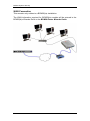
Standalone
In this situation, the BCM is connected directly to a PC.
The required information for this situation would be:
6
BCM System ID
BCM Name
Telephony Region
Time Zone
Time Source
NN40010-318 Issue 1.2 BCM50 Rls 6.0
BCM50 System Start Up
DHCP On/Off?
License File (Keycode File)
Telephony Template
Start DN of the system
Public/Private Received digits
CallPilot Region
CallPilot Password
CallPilot User Interface (UI) Style
CallPilot Attendant DN
Lines to assign to CallPilot Auto-Attendant
LAN Connection
In this situation, the BCM is connected to a Local Area Network.
In addition to the information required for a Standalone installation, you now
need the following details:
IP Address and Subnet Mask for the BCM
If using DHCP, Network Default Gateway,
Domain Name of the DNS server (if the customer has a separate DNS
Server)
IP Address(es) of the DNS server (if relevant)
IP Telephony Registration details (enable, password etc.)
NN40010-318 Issue 1.2 BCM50 Rls 6.0
7
BCM50 System Start Up
WAN Connection
This scenario only relates to a BCM50(b)e installation.
The WAN information required for BCM50(b)e models will be entered in the
BCM50(b)e Wizards. Refer to the BCM50 Router Wizards Guide.
8
NN40010-318 Issue 1.2 BCM50 Rls 6.0
BCM50 System Start Up
Flow Chart
The flow chart outlines the steps involved in System Start-Up:
Which model of BCM50 is being installed?
Standard BCM50
BCM50e
Obtain the Keycode file: refer to
the Obtaining a Keycode file
section of this guide.
Configure a PC to connect to
the BCM: refer to the PC
Configuration section of this
guide.
Configure the Router IP
Address & DHCP settings: refer
to the BCM50 Router LAN
Settings guide.
Set the name of the BCM50:
refer to the Setting the System
Name section of this guide.
Install Element Manager &
Connect to the BCM50: refer to
the Installing the Element
Manager Application section
of this guide.
Enter Keycodes to unlock
features/functionality: refer to
the Software Keycodes
section of this guide.
Ensure the date & Time is
correct: refer to the Setting the
Date & Time section of this
guide.
Configure Telephony Region &
Start DN: refer to the Setting
the Start DN & Telephony
Region section of this guide.
Configure the BCM50 IP
Address: refer to the
Configuring the LAN IP
Address section of this guide.
Initialise CallPilot Manager:
refer to the Initialising
CallPilot Manager section of
this guide.
Configure the DHCP: refer to
the Configuring DHCP section
of this guide.
Configure the Media Bay
Modules: refer to the Media
Bay Modules section of this
guide.
If the BCM50 is to be connected to the
network, refer to the Connecting the BCM to
the Network section of this guide.
NN40010-318 Issue 1.2 BCM50 Rls 6.0
9
BCM50 System Start Up
Obtaining a Keycode File
Keycodes unlock features and applications on the BCM. Without applying
Keycodes it would not even be possible to make a telephone call!
This section describes how to obtain the Keycode file.
Keycodes are generated based on two inputs:
The BCM System ID
Software Authorisation Codes
Software Authorisation Codes are orderable items, and are supplied in paper
form.
There are a number of ways to find the BCM System ID. To find the System
ID without powering up the BCM:
1. Look on the underside of the BCM.
2. You will notice a label with three bar codes on it. The bottom bar code
is the System ID and is labelled SystemID/MAC (it is linked to the MAC
address of the BCM50 LAN ports).
3. Make a note of the System ID; you will need it for Keycode generation.
It will also be required if you wish to use the Startup Profile
Configuration Tool (refer to the Startup Profile Configuration Tool
section of this guide for details of the Startup Profile procedure.)
4. Contact your Keycode supplier and supply the System ID and
Authorisation Codes.
5. You should receive a Keycode file, which will be entered during the
Start Up procedure.
10
NN40010-318 Issue 1.2 BCM50 Rls 6.0
BCM50 System Start Up
PC Configuration
The BCM50 has a dedicated OAM port. It is recommended that you perform
any maintenance/configuration from this port. There are also:
1 x dedicated LAN Port on BCM50, & 5 x dedicated LAN Ports on
BCM50e
2 x dual function ports that act as expansion ports for Media Bay
Modules, and also LAN ports
A PC/laptop can be configured to connect to the BCM OAM in two ways:
Set your PC/laptop to obtain an IP Address automatically (preferred ,
as DHCP is always operating on the OAM port)
Manually set your PC/laptop’s IP Address (IP Address: 10.10.11.2,
Subnet Mask: 255.255.255.252)
(Note that the OAM port default settings are IP Address: 10.10.11.1,
Subnet Mask: 255.255.255.252)
The default setting for the LAN Ports is:
IP Address: 192.168.1.2
Subnet Mask: 255.255.255.0
For information concerning configuring the network settings of your PC, refer
to the Networking Essentials Guide.
NN40010-318 Issue 1.2 BCM50 Rls 6.0
11
BCM50 System Start Up
Physical Connection to the BCM
The BCM50 OAM port can accommodate either a patch cable or a cross-over
cable.
One end of the cable is connected to the PC network card, the other end to
the OAM port of the BCM.
Testing the IP connection using Ping
When a physical connection has been made, you should next test the
connection by “pinging” the BCM. This test is performed on the Laptop/PC
that is connected to the BCM.
1. Go to the Start button on your Windows desktop, and select Run.
2. Type command and press OK. This will bring up the MS-DOS /
command prompt.
12
NN40010-318 Issue 1.2 BCM50 Rls 6.0
BCM50 System Start Up
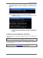
3. Type ping followed by the default IP Address of the LAN port you are
connected to (OAM = 10.10.11.1, LAN Core = 192.168.1.2). Press
Enter.
4. There are differing responses that may now be displayed.
a. If a Reply is received from the BCM (as displayed below) the IP
connection is working.
b. If any other response is displayed, check the IP settings of your
laptop/PC and the physical connection between the laptop/PC
and BCM.
Installing the Element Manager Application
Element Manager is the application that allows configuration of the BCM via a
PC/laptop.
Note: You must ensure you are using the correct version of Element
Manager. The version supplied with the BCM will be the correct version.
The application should be installed on the PC/laptop that is required to
perform configuration.
Note: Java Runtime Environment must be installed on the PC used to access
Application Launcher. Visit www.java.com to download this.
NN40010-318 Issue 1.2 BCM50 Rls 6.0
13
BCM50 System Start Up
1. Point your web browser at the BCM’s IP Address.
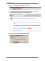
2. You may get presented with the Certificate Error window. If so, click on
the Continue to this website (not recommended) link.
3. If you see the following information box, click Yes.
14
NN40010-318 Issue 1.2 BCM50 Rls 6.0
BCM50 System Start Up
4. You may be presented with a second certificate error message. To
avoid seeing the message again, tick the Always trust content from
this publisher box, and click Yes.
5. Again, you may be presented with a security warning. Tick the Always
trust content from this publisher box to avoid seeing the message in
future, and click Run.
NN40010-318 Issue 1.2 BCM50 Rls 6.0
15
BCM50 System Start Up
6. You will be asked to enter the BCM account credentials. Tick the Save
Credentials and Auto-Login boxes for easier future access. Click OK
when the account details have been entered.
7. In the Application Launcher window, ensure the Main tab is selected.
Click on the BCM button to ensure the required list of applications are
present.
16
NN40010-318 Issue 1.2 BCM50 Rls 6.0
BCM50 System Start Up
8. From the list of Applications, select Business Element Manager and
click on the Run button.
9. The download progress will display.
10. In the Node List Import window, you can browse to a folder containing
a previous BEM installation (e.g. to import previous BEM nodes) and
click on Open. Alternatively, click on Cancel to continue.
NN40010-318 Issue 1.2 BCM50 Rls 6.0
17
BCM50 System Start Up
11. If there hasn’t been a previous installation of Element Manager an
“empty” version (i.e. no preconfigured settings or Elements) will be
presented. If you selected a folder containing a previous installation in
the last step, the existing nodes will be listed in the Element Navigation
Panel.
Note: Subsequent launches of Element Manager from Application Launcher
or via Start, Programs or desktop shortcut will show configured Elements, and
retain Element Manager settings.
18
NN40010-318 Issue 1.2 BCM50 Rls 6.0
BCM50 System Start Up
Element Manager Connection to the BCM
To access Element Manager for configuration purposes:
1. To access the Business Element Manager application from the Start
Menu,
navigate
to
Start,
Programs,
Avaya,
Business
Communications Manager, Business Element Manager.
2. Alternatively, double-click on the Business Element Manager desktop
icon.
NN40010-318 Issue 1.2 BCM50 Rls 6.0
19
BCM50 System Start Up
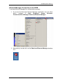
3. You will be presented with the Element Manager interface.
4. Open the Network Elements folder and select the IP Address of the
BCM.
5. Enter the User Name of the BCM in the User Name field, by default this
is nnadmin. Then enter the Password in the Password field, by default
the password is PlsChgMe!. Click the Connect button.
20
NN40010-318 Issue 1.2 BCM50 Rls 6.0
BCM50 System Start Up
6. A warning screen will appear, read the warning and click OK.
7. You will be presented with the Element Manager interface.
Software Keycodes
Note: If you have already applied the Keycodes via the Startup Profile, you
can proceed to the Initialising CallPilot Manager section.
Keycodes are entered in the Keycodes section of Element Manager, and are
entered as a file containing a range of features
Note: When entering the Keycode file, you may be asked to reboot the BCM.
Certain features such as VoIP G/W Trunks, require the BCM to be rebooted.
NN40010-318 Issue 1.2 BCM50 Rls 6.0
21
BCM50 System Start Up
Use the following procedure to load a Keycode file.
1. Access Element Manager (refer to Element Manager Connection to
the BCM section of this guide).
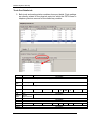
2. In Element Manager, click on the Configuration tab, open the System
folder and click on Keycodes.
3. To load a keycode file, click on the Load Keycode File button.
Note: For new un-configured BCM systems, the Status fields will state IDLE
and the Data fields will show a value of 0.
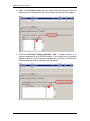
4. Browse to the location of the file and select it. Click Open.
22
NN40010-318 Issue 1.2 BCM50 Rls 6.0
BCM50 System Start Up
5. The features will be applied and viewable in the Feature Licenses
table.
6. If you prompted to reboot the BCM after entering the keycode file
select the Administration tab followed by Utilities, Reboot and then
click the Reboot button.
Note: The feature status change in the keycodes panel may take up to one
minute to display depending on the system load and component response.
You can refresh the keycode window to see the feature status change, after
adding the keycode file, by selecting the refresh button in Element Manager.
Some keycodes require the BCM to be rebooted.
NN40010-318 Issue 1.2 BCM50 Rls 6.0
23
BCM50 System Start Up
Configuring the LAN IP Address
If the IP Address of the BCM system requires changing, i.e. to suit the
customer’s network, use the following procedure.
Note: If configuring a BCM50(b)e, you must ensure that the Router LAN IP
Address and the BCM LAN IP address are on the same subnet. Refer to the
BCM50 Router LAN Settings guide for more information.
All LAN ports will use this IP Address, unless VLANs are to be configured
(refer to the VLANs Guide for more information). The LAN IP Address does
not apply to the OAM port.
1. Access Element Manager (refer to Element Manager Connection to
the BCM section of this guide).
2. In the Configuration tab open the System heading and click on IP
Subsystem.
24
NN40010-318 Issue 1.2 BCM50 Rls 6.0
BCM50 System Start Up
3. Click on the LAN Interfaces tab. Select the Customer LAN row, and
click Modify in the lower part of the screen.
4. Enter the IP Settings as required. You can choose to:
Obtain an IP Address, Subnet Mask, and Default Gateway
automatically (refer to the DHCP Guide for more information
on BCM and DHCP).
Enter an IP Address, Subnet Mask and Default Gateway
manually.
Note: If there is an existing DHCP server on the network, it is recommended
that you specify a static IP Address for the BCM. See the network
administrator about obtaining a static IP Address. Obtaining an IP Address
automatically should generally only be selected when the BCM is acting as
the DHCP Server for the network. Alternatively, consult the network
administrator about reserving an IP Address for the BCM on their DHCP
server.
NN40010-318 Issue 1.2 BCM50 Rls 6.0
25
BCM50 System Start Up
5. If you enter an IP Address manually, you will see the following
WARNING box before you can configure the remaining fields. Click
OK.
6. For manual configuration, continue entering the settings in the other
fields, and click OK.
7. If Obtaining an IP Address dynamically, tick the Obtain IP address
dynamically box. You will see the following WARNING box.
8. Click OK in the WARNING box, and click OK again in the Modify IP
Settings box.
9. You may lose your connection to Element Manager. You will not need
to reboot the BCM. Click the OK button, and reconnect to the BCM
using the new IP address (unless connected via the OAM port).
26
NN40010-318 Issue 1.2 BCM50 Rls 6.0
BCM50 System Start Up
10. If the BCM is obtaining its network settings via DHCP (either its own
DHCP server or one that resides on the network), you can choose to
renew the network settings. To do so, click Renew IP Address.
NN40010-318 Issue 1.2 BCM50 Rls 6.0
27
BCM50 System Start Up
11. DNS settings can also be entered, if you are not receiving this
information via DHCP. In the IP Subsystem area, click on the General
Settings tab, and enter the relevant DNS information in the DNS
Settings fields.
Configuring DHCP
The BCM can be used as the main DHCP server for the network, or it can be
used to provide DHCP information to IP Sets only. Alternatively, DHCP can be
disabled on the BCM if DHCP requirements are being provided by another
device on the network.
Note: The settings detailed in this section do not relate to DHCP on the
BCM50(b)e routers. For information on the BCM50(b)e DHCP settings, refer
to the BCM50 Router LAN Settings Guide.
Note: On the BCM50(b)e models, it is possible to choose between using the
DHCP service on the main DHCP unit, or the DHCP service on the router. If
the router card DHCP service is used, the main module DHCP service is
automatically disabled.
Note: For full instructions on configuring DHCP on the standard BCM50
model, or if using the core DHCP service on the main module rather than the
BCM50(b)e router, refer to the DHCP Guide.
28
NN40010-318 Issue 1.2 BCM50 Rls 6.0
BCM50 System Start Up
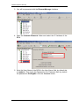
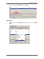
1. From the Configuration tab, open the Data Services folder, and
select DHCP Server.
2. Select the General Settings tab. It is normally selected by default.
3. Configure the DHCP server attributes as required.
4. The BCM does not automatically create an address range of IP
Addresses for allocation to DHCP clients. If the BCM is to be
configured as a DHCP server (for IP Phones only or all devices) you
will need to create an address range. Click on the Address Ranges
tab.
NN40010-318 Issue 1.2 BCM50 Rls 6.0
29
BCM50 System Start Up
5. Click on the Add button. Enter the following settings and click OK:
From IP Address: Start of the range of IP Addresses to be issued to
DHCP clients
To IP Address: End of the range of IP Addresses to be issued to
DHCP clients.
Default Gateway: Gateway address for this range to use.
6. This range will be issued to DHCP clients, if the BCM is configured to
be a DHCP server.
Note: For full details concerning the registration and configuration of IP
Phones, refer to the IP Telephony Guide.
General Settings Screen Settings
Attribute
The DHCP
Server is
IP domain name
Primary DNS IP
address
Secondary DNS
IP address
WINS server
address
WINS node type
30
Value
Disabled
Enabled - IP Phones
Only
Enabled - All Devices
<alphanumeric
character string>
<IP Address, format
10.10.10.10>
<IP Address, format
10.10.10.10>
<IP Address, format
10.10.10.10>
<drop-down menu>
Description
Determines the functionality of the DHCP server.
Default: Enabled – IP Phones Only
The domain name of the network.
The IP address of the primary DNS to be used by DHCP
clients.
The IP address of the secondary DNS to be used by
DHCP clients.
The address of the Windows Internet Server, which
resolves IP addresses on a DHCP network.
The type of WINS node:
B-node: The BCM first checks the HMHOSTS
cache, then uses broadcast for name registration
and resolution.
P-node:The BCM registers with a NetBIOS Name
server at startup.
M-node: Mixes B- and P-node. The BCM uses the
B-node method, and if that fails, uses the P-node
method.
H-node: Uses both B- and P-node methods. B-
NN40010-318 Issue 1.2 BCM50 Rls 6.0
BCM50 System Start Up
Attribute
Lease time(s)
Value
<numeric string>
Description
node is used only as a last resort.
Default: H-node
The amount of time before a DHCP lease expires and the
device must request a new IP address.
Default: 604800 seconds
Setting the System Name
This name is used for identification purposes.
1. From the Configuration tab, open the System folder to expand it.
2. Select Identification from the System folder.
3. Enter a name for your system in the System name field, and press the
tab key.
4. A dialog box will appear advising you of any system interruptions. Click
OK to continue.
NN40010-318 Issue 1.2 BCM50 Rls 6.0
31
BCM50 System Start Up
5. A Progress Update window will appear.
Setting the Date and Time
1. From the Configuration tab, open the System folder to expand it.
2. Select Date and Time from the System folder. The Date and Time
panel displays.
3. Select the appropriate Date and Time Source.
32
NN40010-318 Issue 1.2 BCM50 Rls 6.0
BCM50 System Start Up
4. If setting the Date and Time Source as NTP, click on the Modify
button.
5. Configure the NTP settings as required, and click OK.
6. If setting the Date and Time Source as Manual, click on the Date and
Time drop down arrow, and use the control to select the correct date
and time. Click OK when finished.
NN40010-318 Issue 1.2 BCM50 Rls 6.0
33
BCM50 System Start Up
7. Also ensure that the correct Time Zone is selected.
Date & Time Settings
Attribute
Date and Time
Source
NTP server address
Synch every (s)
NTP security mode
Raise alarm if clock
differs by at least
(s)
NTP key ID
NTP key string
Date and time
Time zone
Description
NTP: Set to NTP (Network Time Protocol) if the system uses
a network server to determine the correct time and date.
Trunk: Set to Trunk to use time and date settings from a CO
through an analog or IDSN line.
Manual: Set to Manual if you want to be able to manually
configure the time and date for your system.
Default: Manual
If Date and Time Source is set to NTP, then enter an
address for the server.
The number of seconds between synchronization with the
NTP server.
Select whether the NTP security mode is secured or
unsecured.
The number of discrepancy seconds specified that must
occur before the system notifies you of a time difference
between the BCM time and the NTP server, if the system
automatically checks with the NTP server.
ID for accessing the NTP server.
Control key corresponding to ID for accessing the NTP
server
Use the dropdown calendar to select the correct date and
time.
Select the time zone for this system.
Setting the Start DN and Telephony Region
Use the following procedure to set your first extension number, telephony
template, and telephony region.
1. From the Administration tab, double-click the Utilities folder to
expand it.
2. Select Reset from the Utilities folder.
34
NN40010-318 Issue 1.2 BCM50 Rls 6.0
BCM50 System Start Up
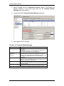
3. Click Cold Reset Telephony Services.
4. The Cold Reset Telephony dialog box displays. Configure the
Telephony Region, Template, and Start DN and click OK.
5. A dialog box will appear advising you of service interruptions. Read the
warnings and click OK.
6. The reset will take a few minutes to perform.It is advisable that you do
not perform any programming until the Cold Reset is complete.
NN40010-318 Issue 1.2 BCM50 Rls 6.0
35
BCM50 System Start Up
Initialising CallPilot Manager
Use the following procedure to initialise the CallPilot Voice Messaging system.
1. From the Configuration tab, open the Applications folder.
2. Select Voice Messaging/Contact Center from the Applications folder.
3. Click Launch CallPilot Manager. If you see the below screen, click on
Continue to this website (not recommended).
36
NN40010-318 Issue 1.2 BCM50 Rls 6.0
BCM50 System Start Up
4. The Quick Install Wizard form displays. If your VoiceMail system is
already initialized, you will not see the Quick Install Wizard.
5. Configure the attributes on the Quick Install Wizard form and click
Install.
6. You will see the INSTALLATION SUCCESSFUL box. Click OK to close
this.
Quick Install Wizard Settings
Attribute
Attendant DN
Primary UI Style
Primary Language
Description
Enter the extension number of the attendant or operator
assigned to CallPilot.
Select the mailbox user interface used as a default for the
mailboxes.
If you select NVM, the mailbox user interface uses Norstar
Voice Mail voice and text prompts.
If you select CallPilot, the mailbox user interface uses
CallPilot voice and text prompts.
Select the language used as the primary language for the
mailboxes.
NN40010-318 Issue 1.2 BCM50 Rls 6.0
37
BCM50 System Start Up
Attribute
From Line
To Line
Number of rings
Description
Enter the line number of the first line in the range of lines you
want CallPilot to answer. CallPilot answers the range of lines
between this line and the line you enter in the To Line box.
Enter the line number of the last line in the range of lines you
want CallPilot to answer.
Enter the number of rings you want CallPilot to wait before
answering lines.
Media Bay Modules
Media Bay Modules can be defined in two main categories:
Trunk Media Bay Modules
Station Media Bay Modules
There are also specialised modules that, for example, provide a combination
of both lines and extensions.
Media Bay Module Configuration
All configurations in this section are performed in Element Manager
Configuration.
Note: Keycodes are required for the Expansion Ports to function. Ensure
these have been entered (refer to the Software Keycodes section of this
guide).
When the Media Bay Modules are configured, the status lights will stop
flashing.
Configuring the Media Bay Modules
1. In Element Manager Configuration tab, open the Resources heading,
and click on Telephony Resources.
38
NN40010-318 Issue 1.2 BCM50 Rls 6.0
BCM50 System Start Up
2. You can now proceed with configuring the Media Bay Module type.
Trunk Media Bay Modules
Media Bay Module
DTM Digital (Trunk Media Bay
Module)
CTM4/CTM8 (Caller ID Media
Bay Module)
Utility
Connects digital public switched telephone
lines to the BCM system (PRI, DASS2,
DPNSS)
Connects a maximum of four (CTM4) or eight
(CTM8) analog public switched telephone
lines to the BCM system.
ISDN BRI Module ( Basic Rate
Interface)
Connects a maximum of four ISDN BRI S/T
interfaces.
GATM4/GATM8
(Global
Analogue Trunk Module)
Connects 4/8 analog public
telephone lines to the BCM system.
ADID4/ADID8
Connects 4/8 Analog Direct Inward Dial trunks
to the system.
switched
PRI Modules
1. Double click the Module Type and select DTM- PRI from the drop
down list. Press the tab key on your keyboard to enforce the change.
NN40010-318 Issue 1.2 BCM50 Rls 6.0
39
BCM50 System Start Up
2. In this example the system has a single PRI Digital Trunk Media Bay
Module installed and the clock source has been set to Primary External
to reflect this. The protocol should also be set as required. In this
example Euro has been selected (other options are SL-1 and QSIG).
Clock Sources and Digital Trunk Modules
For each DTM and BRI, choose one of the following settings: Primary
external, Secondary external, or Internal:
40
Primary external: The DTM/BRI obtains the timing from the network
and the system synchronizes to it. This is the default value for the first
DTM in a BCM. There should only be one defined Primary clock source
on a System. Private network: If this system is in a private network
and is intended to provide the master clock for that private network, the
system must have one, and only one, Primary clock reference on a
DTM or BRI. If this system is intended to act as clock master in a
private network, then all clock sources should be set to Timing Master
on this system.
Secondary external: The DTM/BRI acts as a standby reference point.
If there are excessive errors on the Primary reference link, or the
DTM/BRI designated as Primary reference fails, the Secondary
DTM/BRI obtains the timing from the network to be used for system
synchronization. This is the default value for the second DTM in a
BCM. Private network: If this system is in a private network and is
intended to provide the Master clock for that private network, then there
NN40010-318 Issue 1.2 BCM50 Rls 6.0
BCM50 System Start Up
should be no Secondary reference defined on any DTM/BRI. Note that
there should only be one defined Secondary clock source on a system.
Internal: The DTM/BRI does not obtain timing from the network, but
transmits the internally-generated system timing, from the
Primary/Secondary source, to equipment to which it is connected. Note
that while in the absence of a DTM Primary clocking source a BRI
module can be used for the primary timing reference, it is always
recommended that, when possible, DTM(s) be used as primary (and
secondary) clock sources and that any remaining DTMs/BRIs be set to
Timing Master.
3. The module type has been set. Any module specific settings will be
displayed in the lower window. Note that Line numbers will be
displayed in the Low and High fields for the module.
NN40010-318 Issue 1.2 BCM50 Rls 6.0
41
BCM50 System Start Up
4. As a general rule for Trunk modules (PRI, BRI, DASS2 etc.) you may
wish to check that the lines/loops are provisioned. If the lines/loops are
de-provisioned, the BCM will not have access to those lines/loops.
5. The module should now be Enabled.
42
NN40010-318 Issue 1.2 BCM50 Rls 6.0
BCM50 System Start Up
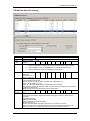
PRI Module-Specific Settings
Attribute
Trunk type
Trunk
mode
Protocol
NSF
Extension
Value
Module/line type
All trunks
Indicates the type of trunks. This field is read-only for all modules except DTM modules.
Loop
DS/CLID, Global,
Legacy
DS/CLID: displays for old North American LS/DS or CLID analog trunk modules,
the old analog MBM, or the GATM with North American DIP switch settings.
Global: displays for the GATM MBM with no regional DIP switches set.
Legacy: displays for all other (old) analog trunk modules
PRI
NI-2, DMS-100,
DMS-250,
AT&T4ESS, SL-1,
Euro, ETSI Q.Sig
Choose the trunk protocol used by your service provider.
The supported protocols are:
PRI-T1: NI (NI-1 and NI-2), DMS-100, DMS-250, AT&T4ESS, SL-1
PRI-E1: ETSI QSIG, Euro, SL-1
Note: SL-1 and ETSI QSIG require an MCDN keycode to display.
BRI: Protocol can also be selected on BRI T-loops under the Configuration > Resources
> Telephony Resources.
Note: Always check the line protocol with the central office.
PRI
None, WATS,
ALL
The Network Specific Facilities (NSF) information element is used to request a particular
service from the network. Settings are based on the type of switch to which the line
connects.
Suggested settings:
DMS-100/250: NONE
Siemens ESWD, Lucent 5ESS: WATS
GTD5, DMS-10: ALL
When you select NONE, the NSF extension bit is not set for any service.
When you select WATS, the NSF extension bit is set for unbanded OUTWATS calls.
When you select ALL, the NSF extension is always set for all CbC services.
NN40010-318 Issue 1.2 BCM50 Rls 6.0
43
BCM50 System Start Up
Attribute
Protocol
type
B-channel
selection
sequence
Answer
timer
Disconnect
timer
Clock
Source
Send
Name
Display
Remote
Capability
MWI
Overlap
receiving
Local
Number
Length
Host node
Local
44
Value
Appears only for NI protocol.
User, Network
Module/line type
PRI
When you select SL-1 protocol, an additional setting, Protocol type, appears.
SL-1 protocol is a private networking protocol. This allows you to designate a BCM node
as a Network (controller). The default setting is User (client). In public network
configurations, the CO is generally considered the Network side or controller.
Applies to SL-1 protocol only.
PRI
Ascending
Sequential
Descending
Sequential
Defines how B-channel resources are selected for call processing.
1, 2, 3, 4, or 5
E&M
PRI
sec.
Set the minimum duration of an answer signal before a call is considered to be answered.
60, 100, 260, 460, Loop
T1
or 600
milliseconds
Specify the duration of an Open Switch Interval (OSI) before a call on a supervised
external line is considered disconnected. This setting must match the setting for the line
at the central office (CO).
You must enable disconnect supervision by changing the Line Trunk mode attribute.
Under the Telephony Services sub-heading, choose Lines and Line/trunk Data.
DASS2
Primary External
T1 PRI *BRI
Secondary
S/T
External
Internal
Designates whether the DTM/BRI acts as a primary or secondary timing component for
an external timing source or as the internal timing source.
Note: A BRI module can be programmed with primary/secondary clock source, however,
it is recommended that a BRI module always be set to Internal if a DTM exists on the
system to be the Primary External clock source.
Warning: Changing the clock source may disconnect calls.
If you change the clock source for your system, you may cause your system DTM
interface(s) to reset, resulting in dropped calls. Choose a suitable time to change the
clock source and use the Page feature to inform users of possible service disruptions.
Select or clear
PRI *BRI
QSIG
When you select this check box, the system sends a specified outgoing name display
(OLI) from the calling telephone.
Appears only for Protocols: SL-1, NI, DMS-100, DMS-250, or PRI QSIG.
Select or clear
PRI
This setting allows you to indicate MWI compatibility on the specific loop(s) that you are
using to connect to the central voice mail system on a Meridian 1 which has the MWI
package installed, with the RCAP setting set to MWI.
Appears only for SL-1 protocol.
BRI
Supports target lines in markets which use Overlap receiving signalling on the BRI trunks.
Overlap receiving must be configured for each BRI loop. After every digit is received at
the ISDN layer, Target Lines are checked for matches. If a full match is made, the call is
routed immediately to the target line without waiting for additional digits.
BRI
When Overlap receiving is enabled on the trunks, this number determines how many
incoming digits need to match the target line numbers to be considered a call for that
target line.
M1, Embark,
DNPSS
IDPX, DSM
DPNSS cards connected to Embark switches have a different way of handling call
diversion, therefore, when you provision a DTM for DPNSS, you must indicate what type
of switch the lines are connected to.
When you select the Embark switch, calls are diverted using the Call Forwarding feature
instead of call diversion.
DPNSS
NN40010-318 Issue 1.2 BCM50 Rls 6.0
BCM50 System Start Up
Attribute
Number
Length
Maximum
Transits
Value
Module/line type
This number allows the system to determine how many digits to read on an incoming call
to determine that the call is meant for this system.
Default: 31
PRI
Indicate the maximum number of times that a call will be transferred within the SL-1
network before the call is dropped. Protocol must be set to SL-1 to display this field.
T1 parameters
T1 PRI
CO fail
Interface
levels
Specify a carrier failure standard (T1A-5474, TR62411)
T1 PRI
ISDN, PSTN
Framing
Define a loss plan setting.
ESF, SF
Line coding
Select the framing format used by your T1 or PRI service provider: Extended Superframe
(ESF) or Superframe (SF). Contact your T1 or PRI service provider for the proper setting.
(SF or Superframe is sometimes known as D4.)
T1 PRI
B8ZS, AMI
Internal
CSU
CSU line
build
DSX1 build
CRC4
T1
PRI
Define the encoding signals on a T1 line. Select the standard used by your T1 service
provider. Contact your T1 service provider for the proper setting.
T1 PRI
<check box>
Turn the internal T1 channel service unit (CSU) on or off.
T1 PRI
0, 7.5, or 15 dB
Set the gain level of the transmitted signal. This setting appears only when the Internal
CSU is Enabled.
T1 PRI
000-100, 100200, 200-300,
300-400, 400500, 500-600, or
600-700 feet
Set the distance between BCM and an external channel service unit. This setting only
appears when the Internal CSU is Disabled. Contact your service provider for the proper
settings.
E1
<check box>
PRI
Ensure this is enabled or disabled to match the service provider Cyclic Redundancy
Check (CRC4) setting for the trunk.
NN40010-318 Issue 1.2 BCM50 Rls 6.0
45
BCM50 System Start Up
DASS2 Modules
1. Double click in the Configured Device field and set it to DTM –
DASS2 module.
2. Configure the options as required.
46
NN40010-318 Issue 1.2 BCM50 Rls 6.0
BCM50 System Start Up
DASS2 Module-Specific Settings
Attribute
Clock
Source
Value
Module / Line Type
Primary
External T1
PRI
*BRI
*BRI U2 *BRI U4 DASS2
Secondary
External
S/T
Internal
Designates whether the DTM/BRI acts as a primary or secondary timing component for an
external timing source or as the internal timing source.
Note: A BRI module can be programmed with primary/secondary clock source, however, it
is recommended that a BRI module always be set to Internal if a DTM exists on the system
to be the Primary External clock source.
Warning:
Changing
the
clock
source
may
disconnect
calls.
If you change the clock source for your system, you may cause your system DTM
interface(s) to reset, resulting in dropped calls. Choose a suitable time to change the clock
source and use the Page feature to inform users of possible service disruptions.
NN40010-318 Issue 1.2 BCM50 Rls 6.0
47
BCM50 System Start Up
Trunk Port Details tab
Port d etails
3. Both trunk and analog station modules show port details. Ports settings
are directly related to the physical ports into which the PSTN lines or
telephony devices connect on the media bay modules.
Attribute
Port #
Value
Module type
All modules
Read-only
These are the port numbers of the physical device.
Device
type
Read-only
Line #
This is the type of module.
00X-XXX
CTM/GATM4
CTM/GATM8
Combo
DTMT1
DTMPRI
BRIT
DN
The number of lines depends on the module type.
All modules
Idle
Active
Deprovisioned
This field indicates whether a module line or DN is in use or even provisioned.
All modules
<read-only>
This field indicates the version of firmware running on the module.
XXXX
Addons
Each port supports one telephone, hence, one DN record.
All modules
Call
State or
State
Version
48
All modules
ASM/GASM
NN40010-318 Issue 1.2 BCM50 Rls 6.0
DSM
BCM50 System Start Up
Attribute
Value
Module type
Indicates auxiliary items added to the telephony devices or trunks
Add-on
This is a list number.
Type
This field indicates the type of add-on, such as a KIM module.
Version
This field indicates the version of firmware running on the add-on device.
4. Open the Provision Lines tab and check that the required lines are
provisioned by clicking each line, and change the setting if necessary.
5. The module should now be Enabled.
NN40010-318 Issue 1.2 BCM50 Rls 6.0
49
BCM50 System Start Up
DPNSS Modules
1. Double click in the Configured Device field and set to DTM - DPNSS
module.
2. From the Host Node option list, select the node type that the BCM is
connected to.
3. Configure the other options as required
50
NN40010-318 Issue 1.2 BCM50 Rls 6.0
BCM50 System Start Up
DPNSS Module-Specific Settings
Attribute
Clock Source
Value
Description
Primary
Secondary
Timing Master
Host node
M1
Embark
IDPX
DSM
DPNSS
Local
Number Length
1-10
Designates whether the DTM/BRI acts as a
primary or secondary timing component for an
external timing source or as the internal timing
source. Note: A BRI module can be
programmed with primary/secondary clock
source, however, it is recommended that a
BRI module always be set to Internal if a DTM
exists on the system to be the Primary
External clock source.
DPNSS cards connected to Embark switches
have a different way of handling call diversion,
therefore, when you provision a DTM for
DPNSS, you must indicate what type of switch
the lines are connected to.
When you select the Embark switch, calls are
diverted using the Call Forwarding feature
instead of call diversion.
This number allows the system to determine
how many digits to read on an incoming call to
determine that the call is meant for this
system.
NN40010-318 Issue 1.2 BCM50 Rls 6.0
51
BCM50 System Start Up
4. Open the Provision Lines tab and check that the required lines are
provisioned by clicking each line, and change the setting if necessary.
5. Click the Provision Virtual Channels Tab. A virtual channel is a
channel assigned to the DPNSS module. If the check box is selected
beside a channel, that channel is available for call traffic. Provision the
Channels as required by checking the tick boxes.
52
NN40010-318 Issue 1.2 BCM50 Rls 6.0
BCM50 System Start Up
6. The module should be Enabled once configured.
BRI Module
1. Double click in the Configured Device field and set it to BRI-ST4
MBM.
NN40010-318 Issue 1.2 BCM50 Rls 6.0
53
BCM50 System Start Up
2. View the Provision Loops tab and check that the required lines are
provisioned by clicking each line, and change the setting if necessary.
3. There are no module-specific settings for BRI modules.
4. The module should now be Enabled.
Use the following procedure to configure the BRI loop type, i.e. S or T and
also the Clock Source settings for the BRI loops.
1. Open Telephony, then Loops.
2. Select the Loop to configure.
54
NN40010-318 Issue 1.2 BCM50 Rls 6.0
BCM50 System Start Up
3. Select the Loop Type from the option box provided.
4. Configure the loops and clock source accordingly.
Loop Settings
Attribute
Value
Description
Loop
Type
<X01-X04>
T
S
Protocol
Euro
QSIG
NI-2
Sampling
(S-loops
only)
Adaptive
Fixed
N/A
ONN
blocking
Suppression
bit
Service code
N/A
Each BRI module supports four loops (eight lines for T-loop programming).
This setting defines whether the loop supports trunks (T-loop) or device
connections
(S-loop).
Note: This variable may be different for different market profiles.
Select the appropriate ISDN protocol.
The values displayed depend on both the market profile and software
keycodes.
Euro - ETSI ISDN standard
QSIG - also an ETSI standard. Only appears if the ETSI QSIG keycode is
loaded.
NI-2
Select a sampling rate for the S-loop.
Fixed: two or more S-interface devices use the loop, and the length of the
loop is less than 200 m (650 ft.).
Adaptive: two or more S-interface devices use the loop, and the length of
the loop is greater than 200 m (650 ft.). If one device is using the loop, the
length of the loop can be a maximum of 1000 m (3230 ft)
Set the Outgoing Name and Number (ONN) Blocking.
When you activate ONN, a user can press FEATURE 819 to block the
outgoing name and number on a per call basis.
Programming note: Ensure that all telephones that have this feature
available are assigned valid OLI numbers. Refer to .
Suppression bit: the system flags the call to the Central Office (CO) so that
the name and number is not sent to the person you call.
Service code: VSC digits are dialed out before the called number to
activate ONN at the central office. These codes are supplied by your
service provider for the lines.
ONN
blocking
NN40010-318 Issue 1.2 BCM50 Rls 6.0
55
BCM50 System Start Up
Attribute
Value
Description
Attribute
Clock
source
Value
Primary
External
Secondary
External
Internal
<check box>
Description
Primary External - uses clock from PSTN
Secondary External - used if system has more than one Loop
Internal - uses clock on BCM
Overlap:
receiving
Overlap:
length
Send Name
Display
(ETSI QSIG
only)
Supports target lines in markets which use Overlap receiving signaling on
the BRI trunks. Overlap receiving must be configured for each BRI loop.
0-10
Set the local number length for loops to interfaces that receive overlap
rather than enbloc digits. This number is the total length of the called party
number received. This number is used to calculate the number of leading
digits that need to be removed by the system.
Note: This parameter appears only when Overlap receiving is enabled.
Example:
Public received number = 4502303
Target line received numbers = 303
Local number length = 7
Public received number length = 3
Thus the first four digits are deleted by the system.
<check box>
If the switch allows outgoing name display, select the check box.
CTM/GATM (4 and 8 port) Module
1. Double click in the Configured Device field and set it to either
CTM8/GATM8 or CTM4/GATM4 depending on which module is
required.
56
NN40010-318 Issue 1.2 BCM50 Rls 6.0
BCM50 System Start Up
2. Then select Expansion 1.1 and configure the Disconnect timer settings
as required. Repeat this process for Expansion 1.2 (CTM8/GATM8
only).
CTM/GATM (4 and 8 port) Module-Specific Settings
Attribute
Disconnect Timer
Value
Description
60-600ms
Set as advised by the CO. Specify the duration of an
Open Switch Interval (OSI) before a call on a
supervised external line is considered disconnected.
This setting must match the setting for the line at the
central office (CO).
You must enable disconnect supervision by changing
the Line Trunk mode attribute.
NN40010-318 Issue 1.2 BCM50 Rls 6.0
57
BCM50 System Start Up
3. Once configured the bus should be Enabled (for the 8-port version, it
will be necessary to Enable both Expansion 1.1 & 1.2).
Station Media Bay Modules
With station media bay modules (MBM) you can connect telephones and
analog telecommunication devices to the BCM system.
Media Bay Module
Utility
DSM16(+)/DSM32(+)
(Digital Station Module)
ASM4/ASM8
GASM8
Connects a maximum of 16 (DSM16+) or 32 (DSM32+) digital
telephones to the BCM system.
Connects 4/8 analog devices to the BCM system.
Connects 4/8 analog devices to the BCM system.
The GASM provides the following additional services: caller ID,
pass through, message waiting indication, and
disconnect supervision at the telephone. The GASM also
allows you to download new firmware.
58
NN40010-318 Issue 1.2 BCM50 Rls 6.0
BCM50 System Start Up
DSM 16/32 Modules
1. Double click in the Configured Device field and from the drop down
list select DSM16 or DSM32 module.
NN40010-318 Issue 1.2 BCM50 Rls 6.0
59
BCM50 System Start Up
2. Both trunk and analog modules show port details. Ports settings are
directly related to the physical ports into which the PSTN lines or
telephony devices connect on the media bay modules.
DSM16/32 Module Specific Settings
Attribute
Port #
Device type
Call State
State
Version
DN
Addons
60
Value
or
Module type
These are the port numbers of the physical device.
Read-only
This is the type of module.
All modules
Idle
Active
Deprovisioned
This field indicates whether a module line or DN is in use or even
provisioned.
All modules
<read-only>
This field indicates the version of firmware running on the
module.
ASM/GASM
DSM
XXXX
Each port supports one telephone, hence, one DN record.
All modules
Indicates auxiliary items added to the telephony devices or
trunks
Add-on
This is a list number.
Type
This field indicates the type of add-on, such as
a KIM module.
Version
This field indicates the version of firmware
running on the add-on device.
NN40010-318 Issue 1.2 BCM50 Rls 6.0
BCM50 System Start Up
3. The bus (or both busses) should now be Enabled.
Note: For the DSM32 MBM both Expansion 1.1 and Expansion 1.2 should be
enabled.
ASM Analog Station Module Configuration
1. Double click in the Configured Device field and from the drop down
list set it to ASM/ASM+ module.
2. There are no module-specific options for these modules.
NN40010-318 Issue 1.2 BCM50 Rls 6.0
61
BCM50 System Start Up
3. The bus should now be Enabled.
Combination Modules
These modules provide a combination of both lines and extensions.
Media Bay Modules
Utility
4x16 Combo
Combination of a CTM4 and a DSM16
Connects a maximum of four analog public switched telephone
lines to the BCM system.
Also connects a maximum of 16 digital telephones to the BCM
system.
Connects 4/8 analog trunks and up to 16 digital extensions to
the BCM system.
G4/8x16
62
NN40010-318 Issue 1.2 BCM50 Rls 6.0
BCM50 System Start Up
Combination Module Configuration
1. Double click in the Configured Device field and select 4 or 8x16
Combo module as required.
2. Then select Expansion 1.1 (and Expansion 1.2 if the 8 x 16 MBM has
been selected) and configure the Trunk Module parameters
accordingly. (Please refer to the CTM/GATM (4 and 8 port) Module
section of this guide).
NN40010-318 Issue 1.2 BCM50 Rls 6.0
63
BCM50 System Start Up
3. Then select Expansion 1.2 (or Expansion 1.3 if the 8 x 16 MBM has
been selected) will be the DSM16 MBM.
4. Once configured, each bus should be Enabled.
64
NN40010-318 Issue 1.2 BCM50 Rls 6.0
BCM50 System Start Up
Connecting the BCM to the Network
NOTE: If the BCM is in a Standalone Installation, this section should be
ignored.
After the BCM has been prepared for the network, and the preceding
initialisation procedures have been performed, the BCM can be connected to
a Local Area Network (LAN).
1.
Plug one end of a standard RJ45 patch cable into one of the LAN ports
of the BCM. Plug the other end of the cable into a network connection
point, e.g. a wall mounted RJ45 socket, or directly into a switch/hub.
Registering IP Terminals
The following procedure describes how to configure the BCM to allow IP
Telephones to register on the BCM.
Note: For full instructions on how to register and set up IP terminals, including
Remote worker sets, refer to the IP Telephony Guide.
1. From the Configuration tab, open the Resources folder to expand it.
2. Select Telephony Resources from the Resources folder.
NN40010-318 Issue 1.2 BCM50 Rls 6.0
65
BCM50 System Start Up
3. Select IP Sets from the Configured Device column. The Details for
Module displays in the lower pane with the IP Terminal Global
Settings tab as the default.
4. Configure the IP Terminal Global Settings attributes.
5. Now register the IP Phones.
IP Sets – IP Terminal Global Settings
Description
Set this value to ON to allow new IP clients to register with
the system.
WARNING: Remember to set Registration to Off when you
have finished registering the new telephones.
Enable global
If you want to require the installer to enter a password when
registration
IP telephones are configured and registered to the system,
password
check this box. If this option is not selected, a user ID
(738662) and password (266344) is requested during IP Set
registration.
Global password
If the Enable Global Registration Password checkbox is
selected, enter the password the installer will enter on the IP
telephone to connect to the system.
Auto-assign DNs
If set to ON, the system assigns an available DN as an IP
terminal requests registration. It does not prompt the installer
to enter a set DN.
Advertisement logo
Any information in this field appears on the display of all IP
telephones. For example, your company name or slogan.
For all other settings, please refer to the IP Telephony Guide.
Attribute
Enable registration
66
NN40010-318 Issue 1.2 BCM50 Rls 6.0
BCM50 System Start Up
Additional Information
Startup Profile Configuration Tool
It is possible to apply Intial settings such as BCM Name, Region, IP Settings,
Start DN, and a Keycode File via a Startup Profile Configuration tool. The
Startup Profile Configuration tool is an alternative method of configuring BCM
initial settings to the previous sections in this guide.
The Startup Profile is configured via an Excel spreadsheet, saved to a USB
stick which is then inserted into the BCM USB port. The BCM is then powered
up whereby the Startup Profile is read and the settings applied
Note: The Startup Profile cannot be run after the Keycodes have been
applied. When the Startup Profile is successfully applied, the BCM system
automatically reboots to complete the system configuration. The Startup
Profile is not fully loaded until the system reboots.
Note: The USB storage device must be formatted for the FAT32 file system. If
necessary, reformat the USB storage device by plugging it into the USB port
of your computer, right-clicking the USB device icon, and selecting FAT32
reformatting. Warning: This destroys any data you had on the USB.
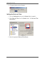
Before Configuring the Startup Profile Configuration Tool
The Startup Profile is configured via an Excel spreadsheet. In order to
configure and save the Startup Profile, the Excel macros need to be disabled.
To set the Excel Macro security settings:
1. With Excel open, go to the Tools menu and select Options.
2. Select the Security tab.
NN40010-318 Issue 1.2 BCM50 Rls 6.0
67
BCM50 System Start Up
3. Click the Macro Security button.
4. Select Medium or Low.
5. Click OK (twice).
6. Exit Excel, open the profile again, and configure as required. You can
then use the large “Save” button at the top of the spreadsheet.
68
NN40010-318 Issue 1.2 BCM50 Rls 6.0
BCM50 System Start Up
Obtaining the Startup Profile Configuration Tool
The Startup Profile Configuration tool can be obtained from the BCM web
page.
To obtain the Startup Profile Configuration tool from the BCM web page:
1. Open Internet Explorer.In the address field type (replacing the relevant
part with your BCM IP address): http://<bcm ip address>/
2. Click on Go, or press Return on your keyboard.
Note: You can also use the Web Page button in Element Manager to launch a
web broswer session. The BCM you wish to access must be selected in the
Element Navigation Panel to do this.
3. If you are presented with the Certificate Error window, click on
Continue to this website (not recommended).
NN40010-318 Issue 1.2 BCM50 Rls 6.0
69
BCM50 System Start Up
4. Accept any further security messages that you may get presented with.
5. You will now see the login screen, enter your BCM User name and
Password. By default these are set to User ID: nnadmin Password:
PlsChgMe! Click on OK.
6. In the Welcome to BCM window, ensure the Main tab has been
selected, and the BCM button clicked.
70
NN40010-318 Issue 1.2 BCM50 Rls 6.0
BCM50 System Start Up
7. From the Applications list, select Other Administrator Applications
and click Run.
8. Again, accept any security messages that appear, and if prompted
enter any login details.
9. The Administrator Applications screen will be displayed.
10. Click on Startup Profile Template, and then Download Startup
Profile Template.
NN40010-318 Issue 1.2 BCM50 Rls 6.0
71
BCM50 System Start Up
11. Select the Save button from the File Download window and save the
Profile template on to your PC.
12. Once saved you can then open the file from its saved location.
72
NN40010-318 Issue 1.2 BCM50 Rls 6.0
BCM50 System Start Up
13. The excel file will open from that location. You may wish to view the
Usage Instructions page.
NN40010-318 Issue 1.2 BCM50 Rls 6.0
73
BCM50 System Start Up
14. Once you have read the instructions select the Startup Profile
Template worksheet.
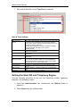
Startup Profile Settings
The following settings are entered in the Startup Profile Configuration Tool.
System Settings
Attribute
System ID
Name
Region
Description
This is the System ID as stated on the System ID label on the BCM
A name for the BCM system
Select your region, e.g. UK.
Time Settings
Attribute
Zone
Clock Control
Year
NTP Server
74
Description
Select the Time Zone, e.g. GMT Edinburgh, London
Options are Core Tel, Manual, or NTP (Network Time Protocol Server)
If selecting Manual, enter the current year
If selecting NTP, enter the IP Address of the Network Time Server
NN40010-318 Issue 1.2 BCM50 Rls 6.0
BCM50 System Start Up
DHCP Server
If Server is set to Enabled, you can specify the Default Gateway, DHCP
Domain, and DNS Servers that will be issued to DHCP Clients
Attribute
Server
DFLTGTWY
Domain Name
DNS1
DNS2
Description
Enable or Disable the core DHCP Server.
Enter the Default Gateway on the network
Domain name for the DHCP Server
Enter the Fully Qualified Domain Name or IP Address of the Primary DNS
Server (if known)
Enter the Fully Qualified Domain Name or IP Address of the Secondary
DNS Server (if known)
IP Address
These settings relate to the LAN interfaces.
Attribute
Dynamic
Address
Subnet
DFLTGTWY
Description
Select Enabled to automatically receive an IP Address etc., or Disabled to
specify a static address, subnet mask and default gateway.
Enter the required IP Address of the LAN 1 interface.
Enter the required Subnet Mask for the LAN 1 interface.
Enter the Default Gateway for the LAN 1 interface.
Modem
Select whether or not to enable the software modem, which can be used for
Remote Dial-in purposes.
Keycodes
If you have received a Keycode file and wish to apply it using the Startup
Profile, enter the name of the file here. The Keycode file must be located in
the root of the USB drive
Telephony Startup Settings
Attribute
Template
Start DN
Description
DID: Systems configured using the DID template, automatically assign
target lines to all DNs. Use this template if DDI numbers are used.
PBX: Pool A is automatically assigned for all DNs. Use this template in
situations where calls are routed through an operator.
Enter the first extensions number for your system.
IP Telephones
Attribute
Registration
Use
Global
Password
Global Password
Auto Assign
Advertisement
Description
Enabled or Disable IP Set registration
If Yes, the IP set installer will have to enter the password set in the Global
Password field
If using Global Password, enter a password for the IP set installer to enter
If Enabled, DNs will automatically be assigned to the IP sets
This is the display on the handset
NN40010-318 Issue 1.2 BCM50 Rls 6.0
75
BCM50 System Start Up
Other Settings
It is recommended that the rest of the settings in the Startup Profile
Configuration Tool are left at default, as omitting certain fields can cause the
Startup Profile to fail.
15. Continuing with the configuration, enter your BCM system ID in the
System ID field in the Startup Profile template.
16. The system ID can be found from within Element Manager by opening
the System folder and selecting keycodes link. It can also be
displayed from a BCM telephone by pressing the Feature key and
entering **SYSID.
17. Enter the remaining information into the Startup Profile editor that you
want loaded onto the BCM. The Startup Profile editor contains
explanations of the various parameters. Simply click on the cell where
you want to enter information and the help text appears. You can
choose which parameters to load onto your system by selecting Apply
for the parameters you want to load. If you do not want to load certain
parameters, select Ignore.
76
NN40010-318 Issue 1.2 BCM50 Rls 6.0
BCM50 System Start Up
18. If using a Keycode file, ensure you type in the name of the file correctly
(e.g. 001158FF9B9C_01.lic).
Note: The Keycode file should be copied to the root directory of the USB
stick.
NN40010-318 Issue 1.2 BCM50 Rls 6.0
77
BCM50 System Start Up
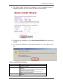
19. Once you have entered the configuration details as outlined in the
following table click the large button at the top of the Startup Profile
template to save a version of the Startup Profile (.sps file) and a
version of the Startup Profile editor (Excel spreadsheet) on your
computer.
Note: You cannot copy and paste data between cells in the Startup Profile.
If you attempt this, the data validation within the spreadsheet becomes
corrupt. If corruption occurs, download another copy of the Startup Profile
template from the BCM main unit. Also never edit the Startup Profile (.sps
file) directly; always use the Startup Profile editor to make changes.
20. You will be presented with warning screen below.
78
NN40010-318 Issue 1.2 BCM50 Rls 6.0
BCM50 System Start Up
21. Save a version of the Startup Profile (.sps file) on the USB memory
stick. This will be noted as a drive letter in Windows Explorer.
22. The filenames for the Startup Profile editor and the Startup Profile
consist of the system ID followed by the appropriate extension.
23. Exit from Microsoft Excel.
Running the Startup Profile
1. Ensure that
a. The BCM is turned off.
b. There are no data cables plugged into the BCM.
c. The amphenol (telephony) connector is not plugged in.
2. Insert the USB memory stick into the USB port on the front of the BCM
main unit.
3. Plug in the power cable.
4. The BCM will automatically detect the USB stick, read the Startup
Profile, and apply the settings to the BCM.
5. When the BCM has fully booted (both status and power lights will be
fully lit), remove the USB stick and insert the telephony connector.
NN40010-318 Issue 1.2 BCM50 Rls 6.0
79
BCM50 System Start Up
Next Step
When the Startup Profile has been applied, you should continue with the
Media Bay Module Configuration section of this guide.
Keycode Credit System
It is now possible to remove software entitlements from one BCM and add
them to a pool for distribution to other BCM systems. A Distributor or Avaya
Channel Partner would manage the entitlement pool, whereas the BCM
installer would apply a Keycode file sent from the Keycode supplier with a
reduced set of features onto the BCM, and generate a Credit Proof File to
send back to the Keycode supplier so that “liberated” Keycodes can be
applied to the entitlement pool. When the Keycodes have been entered into
the entitlement pool, they can be distributed to other BCM systems.
Note: At present, the Keycode Credit System is only applicable to BCM Rls
5.0 or later BCM’s. Also, transferral of Keycodes between BCM50 and other
platforms (and vice versa) is not possible.
Note: Entitlements can only be transferred between BCM’s belonging to the
same customer. Also, each BCM must be registered to the customer’s
entitlement pool in the Keycode Retrieval System (KRS).
An overview of the process or removing Keycodes from a donor BCM and
applying these to the entitlement pool for distribution is described as follows:
1. In the Avaya Keycode Retrieval System (KRS), generate a Keycode
with reduced entitlements then apply it to the donor BCM.
2. Generate a Keycode Credit Proof file and reboot the BCM (this
deactivates the features on the donor BCM that you wish to transfer to
other BCMs).
3. Transfer Credit Proof file to KRS to activate the credit.
4. KRS Validates the Credit proof file and the Credit becomes available to
the customer.
5. The credits can be transferred to another BCM (through a new
KeyCode containing the additional entitlements).
80
NN40010-318 Issue 1.2 BCM50 Rls 6.0
BCM50 System Start Up
The BCM installer’s responsibilities can be summarized as follows:
1. Apply the Keycode file with reduced entitlement to the donor BCM.
2. Generate a Credit Proof File on the donor BCM. The BCM will require
rebooting.
3. Send the Credit Proof File to the Keycode supplier.
4. Keycode files generated from the entitlement pool are applied in the
same way as regular Keycode files.
NN40010-318 Issue 1.2 BCM50 Rls 6.0
81
BCM50 System Start Up
Avaya Documentation Links
82
Installation and Maintenance Guide
BCM50 Installation Checklist and Quick Start Guide
Keycode Installation Guide
Configuration – System
Configuration – Devices
Configuration – Telephony
NN40010-318 Issue 1.2 BCM50 Rls 6.0