1
Nortel Ethernet Routing Switch 8600
Quick Start
Release: 5.0
Document Revision: 02.01
www.nortel.com
NN46205-310
.
321749-B Rev 01
Nortel Ethernet Routing Switch 8600
Release: 5.0
Publication: NN46205-310
Document status: Standard
Document release date: 30 May 2008
Copyright © 2008 Nortel Networks
All Rights Reserved.
Printed in Canada, India, and the United States of America
LEGAL NOTICE
While the information in this document is believed to be accurate and reliable, except as otherwise expressly
agreed to in writing NORTEL PROVIDES THIS DOCUMENT "AS IS" WITHOUT WARRANTY OR CONDITION OF
ANY KIND, EITHER EXPRESS OR IMPLIED. The information and/or products described in this document are
subject to change without notice.
Nortel, the Nortel logo, the Globemark, and Passport are trademarks of Nortel Networks.
All other trademarks are the property of their respective owners.
ATTENTION
For information about the regulatory and safety precautions, read "Regulatory messages and safety
precautions" in this guide.
For information about the software license, read "Software license" in this guide.
For a list of safety messages used in this guide and their translations, see "Translations of safety
messages".
.
3
.
Contents
Regulatory Information and Safety Precautions
5
Software license
17
New in this release
21
Features 21
Other changes 21
Connecting the modem using the CLI 22
Connecting the modem using the NNCLI 22
Setting the system date and time using the CLI 22
Setting the system date and time using the NNCLI 22
Changing passwords using the CLI 22
Changing passwords using the NNCLI 22
Introduction
23
Installation preparation
Ethernet Routing Switch 8600 slots
DC power supply accessories 26
Safety precautions 27
Personal safety 27
25
25
Installation
31
Unpacking the chassis 32
Removing a power filler panel 33
Installing an Ethernet Routing Switch 8003, 8006, or 8010 chassis into a rack
Installing the 8010co chassis in a 19-inch two-post rack 36
Installing the 8003, 8006, and 8010 chassis cable guides 37
Installing the top cable-management bracket 38
Procedure job aid: Installing the cable-management brackets 39
Installing the side cable-management brackets 39
Grounding the 8010co chassis 40
Procedure job aid: Grounding the 8010co chassis 41
Installing a module 41
Procedure job aid: Installing a module 43
Installing AC power modules 43
Nortel Ethernet Routing Switch 8600
Quick Start
NN46205-310 02.01 Standard
30 May 2008
Copyright © 2008 Nortel Networks
.
34
4
Installing DC power modules 44
Cable preparation 49
Installing a breaker interface panel 49
Installing a PCMCIA software card 49
Starting the system 49
Turning on AC power supplies 49
Turning on DC power supplies 50
LED power supply 51
Verifying a successful installation 51
Configuration
53
Connecting a modem using the CLI 53
Connecting a modem using the NNCLI 56
Connecting a VT-100 terminal or PC for local access 58
Setting system date and time using the CLI 59
Procedure job aid: config setdate command sample output
Setting system date and time using the NNCLI 59
Procedure job aid: clock set command output 59
Changing passwords using the CLI 60
Changing passwords using the NNCLI 63
Configuring the system using the setup utility 65
Procedure job aid: Setup Utility prompt descriptions 66
Translation of safety messages
Fan tray safety warning message 69
Preventing back injury warning statement 70
Preventing electrical shock warning statement 72
Preventing hand injury warning statement 73
Safety danger statement 74
Injury to eye warning statement 75
Safety practices and the hazards danger statement
Safety practices and the hazards danger statement
Preventing electric shock danger statement 80
Nortel Ethernet Routing Switch 8600
Quick Start
NN46205-310 02.01 Standard
30 May 2008
Copyright © 2008 Nortel Networks
.
59
69
77
78
5
.
Regulatory Information and Safety
Precautions
Read the information in this section to learn about regulatory conformities
and compliances.
International Regulatory Statements of Conformity
This is to certify that the Nortel 8000 Series chassis and components
installed within the chassis were evaluated to the international regulatory
standards for electromagnetic compliance (EMC) and safety and were
found to have met the requirements for the following international
standards:
•
•
•
EMC—Electromagnetic Emissions—CISPR 22, Class A
EMC—Electromagnetic Immunity—CISPR 24
Electrical Safety—IEC 60950, with CB member national deviations
Further, the equipment has been certified as compliant with the national
standards as detailed in the following sections.
National Electromagnetic Compliance (EMC) Statements of
Compliance
FCC Statement (USA only)
This equipment has been tested and found to comply with the limits for a
Class A digital device, pursuant to Part 15 of the Federal Communications
Commission (FCC) rules. These limits are designed to provide reasonable
protection against harmful interference when the equipment is operated
in a commercial environment. This equipment generates, uses, and can
radiate radio frequency energy. If it is not installed and used in accordance
with the instruction manual, it may cause harmful interference to radio
communications. Operation of this equipment in a residential area is likely
to cause harmful interference, in which case users will be required to take
whatever measures may be necessary to correct the interference at their
own expense.
Nortel Ethernet Routing Switch 8600
Quick Start
NN46205-310 02.01 Standard
30 May 2008
Copyright © 2008 Nortel Networks
.
6 Regulatory Information and Safety Precautions
ICES Statement (Canada only)
Canadian Department of Communications Radio Interference
Regulations
This digital apparatus (8000 Series chassis and installed components)
does not exceed the Class A limits for radio-noise emissions from
digital apparatus as set out in the Radio Interference Regulations of the
Canadian Department of Communications.
Règlement sur le brouillage radioélectrique du ministère des
Communications
Cet appareil numérique (8000 Series chassis) respecte les limites de bruits
radioélectriques visant les appareils numériques de classe A prescrites
dans le Règlement sur le brouillage radioélectrique du ministère des
Communications du Canada.
CE Marking Statement (Europe only)
EN 55 022 Statements
This is to certify that the Nortel 8000 Series chassis and components
installed within the chassis are shielded against the generation of radio
interference in accordance with the application of Council Directive
2004/108/EC. Conformity is declared by the application of EN 55 022
Class A (CISPR 22).
CAUTION
This device is a Class A product. Operation of this equipment
in a residential area is likely to cause harmful interference, in
which case users are required to take appropriate measures
necessary to correct the interference at their own expense.
EN 55 024 Statement
This is to certify that the Nortel 8000 Series chassis is shielded against the
susceptibility to radio interference in accordance with the application of
Council Directive 2004/108/EC. Conformity is declared by the application
of EN 55 024 (CISPR 24).
EN 300386 Statement
The Ethernet Routing Switch 8000 Series chassis complies with the
requirements of EN 300386 V1.3.3 for emissions and for immunity for a
Class A device intended for use in either Telecommunications centre or
locations other than telecommunications centres given the performance
criteria as specified by the manufacturer.
EC Declaration of Conformity
This product conforms to the provisions of the R&TTE Directive
1999/5/EC.
Nortel Ethernet Routing Switch 8600
Quick Start
NN46205-310 02.01 Standard
30 May 2008
Copyright © 2008 Nortel Networks
.
National Electromagnetic Compliance (EMC) Statements of Compliance 7
European Union and European Free Trade Association (EFTA) Notice
All products labeled with the CE marking comply with R&TTE Directive
(1999/5/EEC) which includes the Electromagnetic Compliance (EMC)
Directive (2004/108/EC) and the Low Voltage Directive (2006/95/EC)
issued by the Commission of the European Community.
Compliance with these directives implies conformity to the following
European Norms (ENs). The equivalent international standards are listed
in parenthesis.
•
•
EN 55022 (CISPR 22)–Electromagnetic Interference
•
•
EN 61000-3-2 (IEC 610000-3-2)–Power Line Harmonics
EN 55024 (IEC 61000-4-2, -3, -4, -5, -6, -8, -11)–Electromagnetic
Immunity
EN 61000-3-3 (IEC 610000-3-3)–Power Line Flicker
VCCI Statement (Japan/Nippon only)
This is a Class A product based on the standard of the Voluntary Control
Council for Interference (VCCI) for information technology equipment.
If this equipment is used in a domestic environment, radio disturbance
may arise. When such trouble occurs, the user may be required to take
corrective actions.
BSMI Statement for 8010, 8006 and 8003 Chassis (Taiwan only)
This is a Class A product based on the standard of the Bureau of
Standards, Metrology and Inspection (BSMI) CNS 13438, Class A.
MIC Notice for 8010, 8006, 8003 Chassis (Republic of Korea only)
This device has been approved for use in Business applications only per
the Class A requirements of the Republic of Korea Ministry of Information
and Communications (MIC). This device may not be sold for use in a
non-business application.
Nortel Ethernet Routing Switch 8600
Quick Start
NN46205-310 02.01 Standard
30 May 2008
Copyright © 2008 Nortel Networks
.
8 Regulatory Information and Safety Precautions
National Safety Statements of Compliance
CE Marking Statement (Europe only)
EN 60 950 Statement
This is to certify that the Nortel 8000 Series chassis and components
installed within the chassis are in compliance with the requirements of EN
60 950 in accordance with the Low Voltage Directive. Additional national
differences for all European Union countries have been evaluated for
compliance. Some components installed within the 8000 Series chassis
may use a nickel-metal hydride (NiMH) and/or lithium-ion battery. The
NiMH and lithium-ion batteries are long-life batteries, and it is very possible
that you will never need to replace them. However, should you need to
replace them, refer to the individual component manual for directions on
replacement and disposal of the battery.
NOM Statement 8010, 8006, and 8003 Chassis (Mexico only)
The following information is provided on the devices described in this
document in compliance with the safety requirements of the Norma Oficial
Méxicana (NOM):
Exporter:
Nortel Networks, Inc.
4655 Great America Parkway
Santa Clara CA 95054 USA
Importer:
Nortel Networks de México, S.A. de C.V.
Avenida Insurgentes Sur #1605
Piso 30, Oficina
Col. San Jose Insurgentes
Deleg-Benito Juarez
Nortel Ethernet Routing Switch 8600
Quick Start
NN46205-310 02.01 Standard
30 May 2008
Copyright © 2008 Nortel Networks
.
National Safety Statements of Compliance 9
México D.F. 03900
Tel:
52 5 480 2100
Fax:
52 5 480 2199
Input:
Model 8003AC:
100-240 VAC, 50-60 Hz, 9 A maximum for each power
supply
Model 8004AC:
100-240 VAC, 50-60 Hz, 12-6 A maximum for each
power supply
Model 8005AC:
100-120 VAC, 50-60 Hz, 16 A maximum for each
power supply
200-240 VAC, 50-60 Hz, 8.5 A maximum for each
power supply
Model 8005DI AC:
100-120 VAC, 50-60 Hz, 16 A maximum for each
power supply
200-240 VAC, 50-60 Hz, 9.3 A maximum for each
power supply
Model 8004DC:
48-60 VDC, 29-23 A
Model 8005DC:
48-60 VDC, 42-34 A
Información NOM (unicamente para México)
La información siguiente se proporciona en el dispositivo o en los
dispositivos descritos en este documento, en cumplimiento con los
requisitos de la Norma Oficial Méxicana (NOM):
Exportador:
Nortel Networks, Inc.
4655 Great America Parkway
Santa Clara, CA 95054 USA
Importador:
Nortel Networks de México, S.A. de C.V.
Avenida Insurgentes Sur #1605
Piso 30, Oficina
Nortel Ethernet Routing Switch 8600
Quick Start
NN46205-310 02.01 Standard
30 May 2008
Copyright © 2008 Nortel Networks
.
10 Regulatory Information and Safety Precautions
Col. San Jose Insurgentes
Deleg-Benito Juarez
México D.F. 03900
Tel:
52 5 480 2100
Fax:
52 5 480 2199
Embarcar a:
Model 8003AC:
100-240 VCA, 50-60 Hz, 9 A max. por fuente de poder
Model 8004AC:
100-240 VCA, 50-60 Hz, 12-6 A max. por fuente de
poder
Model 8005AC:
100-120 VCA, 50-60 Hz, 16 A max. por fuente de
poder
200-240 VCA, 50-60 Hz, 9.5 A max. por fuente de
poder
Model 8005DI AC:
100-120 VCA, 50-60 Hz, 16 A max por fuente de poder
200-240 VCA, 50-60 Hz, 9.3 A max por fuente de
poder
Model 8004DC:
-48 VCD, 29 A
Model 8005DC:
-48 VCD, 42 A
Denan Statement (Japan/Nippon only)
Nortel Ethernet Routing Switch 8600
Quick Start
NN46205-310 02.01 Standard
30 May 2008
Copyright © 2008 Nortel Networks
.
Safety Messages
11
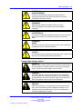
Safety Messages
This section describes the different precautionary notices used in this
document. This section also contains precautionary notices that you must
read for safe operation of the Nortel Ethernet Routing Switch 8600.
Notices
Notice paragraphs alert you about issues that require your attention.
The following sections describe the types of notices. For a list of safety
messages used in this guide and their translations, see "Translations of
safety messages".
Attention Notice
ATTENTION
An attention notice provides important information regarding the installation and
operation of Nortel products.
Caution ESD Notice
CAUTION
ESD
ESD notices provide information about how to avoid discharge
of static electricity and subsequent damage to Nortel products.
CAUTION
ESD (décharge électrostatique)
La mention ESD fournit des informations sur les moyens de
prévenir une décharge électrostatique et d’éviter d’endommager
les produits Nortel.
CAUTION
ACHTUNG ESD
ESD-Hinweise bieten Information dazu, wie man die
Entladung von statischer Elektrizität und Folgeschäden an
Nortel-Produkten verhindert.
CAUTION
PRECAUCIÓN ESD (Descarga electrostática)
El aviso de ESD brinda información acerca de cómo evitar
una descarga de electricidad estática y el daño posterior a los
productos Nortel.
CAUTION
CUIDADO ESD
Os avisos do ESD oferecem informações sobre como evitar
descarga de eletricidade estática e os conseqüentes danos aos
produtos da Nortel.
Nortel Ethernet Routing Switch 8600
Quick Start
NN46205-310 02.01 Standard
30 May 2008
Copyright © 2008 Nortel Networks
.
12 Regulatory Information and Safety Precautions
CAUTION
ATTENZIONE ESD
Le indicazioni ESD forniscono informazioni per evitare scariche
di elettricità statica e i danni correlati per i prodotti Nortel.
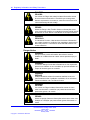
Caution Notice
CAUTION
Caution notices provide information about how to avoid possible
service disruption or damage to Nortel products.
CAUTION
ATTENTION
La mention Attention fournit des informations sur les moyens
de prévenir une perturbation possible du service et d’éviter
d’endommager les produits Nortel.
CAUTION
ACHTUNG
Achtungshinweise bieten Informationen dazu, wie man mögliche
Dienstunterbrechungen oder Schäden an Nortel-Produkten
verhindert.
CAUTION
PRECAUCIÓN
Los avisos de Precaución brindan información acerca de
cómo evitar posibles interrupciones del servicio o el daño a los
productos Nortel.
CAUTION
CUIDADO
Os avisos de cuidado oferecem informações sobre como evitar
possíveis interrupções do serviço ou danos aos produtos da
Nortel.
CAUTION
ATTENZIONE
Le indicazioni di attenzione forniscono informazioni per evitare
possibili interruzioni del servizio o danni ai prodotti Nortel.
Warning Notice
WARNING
Warning notices provide information about how to avoid
personal injury when working with Nortel products.
Nortel Ethernet Routing Switch 8600
Quick Start
NN46205-310 02.01 Standard
30 May 2008
Copyright © 2008 Nortel Networks
.
Safety Messages
13
WARNING
AVERTISSEMENT
La mention Avertissement fournit des informations sur
les moyens de prévenir les risques de blessure lors de la
manipulation de produits Nortel.
WARNING
WARNUNG
Warnhinweise bieten Informationen dazu, wie man
Personenschäden bei der Arbeit mit Nortel-Produkten
verhindert.
WARNING
ADVERTENCIA
Los avisos de Advertencia brindan información acerca de cómo
prevenir las lesiones a personas al trabajar con productos
Nortel.
WARNING
AVISO
Os avisos oferecem informações sobre como evitar ferimentos
ao trabalhar com os produtos da Nortel.
WARNING
AVVISO
Le indicazioni di avviso forniscono informazioni per evitare danni
alle persone durante l’utilizzo dei prodotti Nortel.
Danger High Voltage Notice
DANGER
Danger—High Voltage notices provide information about how to
avoid a situation or condition that can cause serious personal
injury or death from high voltage or electric shock.
DANGER
La mention Danger—Tension élevée fournit des informations
sur les moyens de prévenir une situation ou une condition qui
pourrait entraîner un risque de blessure grave ou mortelle à la
suite d’une tension élevée ou d’un choc électrique.
DANGER
GEFAHR
Hinweise mit Vorsicht – Hochspannung“ bieten Informationen
dazu, wie man Situationen oder Umstände verhindert, die zu
schweren Personenschäden oder Tod durch Hochspannung
oder Stromschlag führen können.
Nortel Ethernet Routing Switch 8600
Quick Start
NN46205-310 02.01 Standard
30 May 2008
Copyright © 2008 Nortel Networks
.
14 Regulatory Information and Safety Precautions
DANGER
PELIGRO
Los avisos de Peligro-Alto voltaje brindan información acerca
de cómo evitar una situación o condición que cause graves
lesiones a personas o la muerte, a causa de una electrocución
o de una descarga de alto voltaje.
DANGER
PERIGO
Avisos de Perigo—Alta Tensão oferecem informações sobre
como evitar uma situação ou condição que possa causar graves
ferimentos ou morte devido a alta tensão ou choques elétricos.
DANGER
PERICOLO
Le indicazioni Pericolo—Alta tensione forniscono informazioni
per evitare situazioni o condizioni che potrebbero causare gravi
danni alle persone o il decesso a causa dell’alta tensione o di
scosse elettriche.
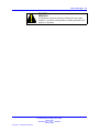
Danger Notice
DANGER
Danger notices provide information about how to avoid a
situation or condition that can cause serious personal injury or
death.
DANGER
La mention Danger fournit des informations sur les moyens de
prévenir une situation ou une condition qui pourrait entraîner un
risque de blessure grave ou mortelle.
DANGER
GEFAHR
Gefahrenhinweise stellen Informationen darüber bereit, wie
man Situationen oder Umständen verhindert, die zu schweren
Personenschäden oder Tod führen können.
DANGER
PELIGRO
Los avisos de Peligro brindan información acerca de cómo
evitar una situación o condición que pueda causar lesiones
personales graves o la muerte.
DANGER
PERIGO
Avisos de perigo oferecem informações sobre como evitar uma
situação ou condição que possa causar graves ferimentos ou
morte.
Nortel Ethernet Routing Switch 8600
Quick Start
NN46205-310 02.01 Standard
30 May 2008
Copyright © 2008 Nortel Networks
.
Safety Messages
DANGER
PERICOLO
Le indicazioni di pericolo forniscono informazioni per evitare
situazioni o condizioni che potrebbero causare gravi danni alle
persone o il decesso.
Nortel Ethernet Routing Switch 8600
Quick Start
NN46205-310 02.01 Standard
30 May 2008
Copyright © 2008 Nortel Networks
.
15
16 Regulatory Information and Safety Precautions
Nortel Ethernet Routing Switch 8600
Quick Start
NN46205-310 02.01 Standard
30 May 2008
Copyright © 2008 Nortel Networks
.
17
.
Software license
This section contains the Nortel Networks software license.
Nortel Networks Inc. software license agreement
This Software License Agreement ("License Agreement") is between
you, the end-user ("Customer") and Nortel Networks Corporation and
its subsidiaries and affiliates ("Nortel Networks"). PLEASE READ THE
FOLLOWING CAREFULLY. YOU MUST ACCEPT THESE LICENSE
TERMS IN ORDER TO DOWNLOAD AND/OR USE THE SOFTWARE.
USE OF THE SOFTWARE CONSTITUTES YOUR ACCEPTANCE OF
THIS LICENSE AGREEMENT. If you do not accept these terms and
conditions, return the Software, unused and in the original shipping
container, within 30 days of purchase to obtain a credit for the full
purchase price.
"Software" is owned or licensed by Nortel Networks, its parent or one of
its subsidiaries or affiliates, and is copyrighted and licensed, not sold.
Software consists of machine-readable instructions, its components, data,
audio-visual content (such as images, text, recordings or pictures) and
related licensed materials including all whole or partial copies. Nortel
Networks grants you a license to use the Software only in the country
where you acquired the Software. You obtain no rights other than those
granted to you under this License Agreement. You are responsible for the
selection of the Software and for the installation of, use of, and results
obtained from the Software.
1. Licensed Use of Software. Nortel Networks grants Customer a
nonexclusive license to use a copy of the Software on only one machine
at any one time or to the extent of the activation or authorized usage level,
whichever is applicable. To the extent Software is furnished for use with
designated hardware or Customer furnished equipment ("CFE"), Customer
is granted a nonexclusive license to use Software only on such hardware
or CFE, as applicable. Software contains trade secrets and Customer
agrees to treat Software as confidential information using the same care
and discretion Customer uses with its own similar information that it does
not wish to disclose, publish or disseminate. Customer will ensure that
anyone who uses the Software does so only in compliance with the terms
Nortel Ethernet Routing Switch 8600
Quick Start
NN46205-310 02.01 Standard
30 May 2008
Copyright © 2008 Nortel Networks
.
18 Software license
of this Agreement. Customer shall not a) use, copy, modify, transfer
or distribute the Software except as expressly authorized; b) reverse
assemble, reverse compile, reverse engineer or otherwise translate the
Software; c) create derivative works or modifications unless expressly
authorized; or d) sublicense, rent or lease the Software. Licensors of
intellectual property to Nortel Networks are beneficiaries of this provision.
Upon termination or breach of the license by Customer or in the event
designated hardware or CFE is no longer in use, Customer will promptly
return the Software to Nortel Networks or certify its destruction. Nortel
Networks may audit by remote polling or other reasonable means to
determine Customer’s Software activation or usage levels. If suppliers of
third party software included in Software require Nortel Networks to include
additional or different terms, Customer agrees to abide by such terms
provided by Nortel Networks with respect to such third party software.
2. Warranty. Except as may be otherwise expressly agreed to in
writing between Nortel Networks and Customer, Software is provided
"AS IS" without any warranties (conditions) of any kind. NORTEL
NETWORKS DISCLAIMS ALL WARRANTIES (CONDITIONS) FOR THE
SOFTWARE, EITHER EXPRESS OR IMPLIED, INCLUDING, BUT NOT
LIMITED TO THE IMPLIED WARRANTIES OF MERCHANTABILITY AND
FITNESS FOR A PARTICULAR PURPOSE AND ANY WARRANTY OF
NON-INFRINGEMENT. Nortel Networks is not obligated to provide support
of any kind for the Software. Some jurisdictions do not allow exclusion
of implied warranties, and, in such event, the above exclusions may not
apply.
3. Limitation of Remedies. IN NO EVENT SHALL NORTEL
NETWORKS OR ITS AGENTS OR SUPPLIERS BE LIABLE FOR ANY
OF THE FOLLOWING: a) DAMAGES BASED ON ANY THIRD PARTY
CLAIM; b) LOSS OF, OR DAMAGE TO, CUSTOMER’S RECORDS,
FILES OR DATA; OR c) DIRECT, INDIRECT, SPECIAL, INCIDENTAL,
PUNITIVE, OR CONSEQUENTIAL DAMAGES (INCLUDING LOST
PROFITS OR SAVINGS), WHETHER IN CONTRACT, TORT OR
OTHERWISE (INCLUDING NEGLIGENCE) ARISING OUT OF
YOUR USE OF THE SOFTWARE, EVEN IF NORTEL NETWORKS,
ITS AGENTS OR SUPPLIERS HAVE BEEN ADVISED OF THEIR
POSSIBILITY. The forgoing limitations of remedies also apply to any
developer and/or supplier of the Software. Such developer and/or supplier
is an intended beneficiary of this Section. Some jurisdictions do not allow
these limitations or exclusions and, in such event, they may not apply.
4.
General
1. If Customer is the United States Government, the following paragraph
shall apply: All Nortel Networks Software available under this License
Agreement is commercial computer software and commercial computer
Nortel Ethernet Routing Switch 8600
Quick Start
NN46205-310 02.01 Standard
30 May 2008
Copyright © 2008 Nortel Networks
.
Nortel Networks Inc. software license agreement
19
software documentation and, in the event Software is licensed for
or on behalf of the United States Government, the respective rights
to the software and software documentation are governed by Nortel
Networks standard commercial license in accordance with U.S. Federal
Regulations at 48 C.F.R. Sections 12.212 (for non-DoD entities) and
48 C.F.R. 227.7202 (for DoD entities).
2. Customer may terminate the license at any time. Nortel Networks
may terminate the license if Customer fails to comply with the terms
and conditions of this license. In either event, upon termination,
Customer must either return the Software to Nortel Networks or certify
its destruction.
3. Customer is responsible for payment of any taxes, including personal
property taxes, resulting from Customer’s use of the Software.
Customer agrees to comply with all applicable laws including all
applicable export and import laws and regulations.
4. Neither party may bring an action, regardless of form, more than two
years after the cause of the action arose.
5. The terms and conditions of this License Agreement form the complete
and exclusive agreement between Customer and Nortel Networks.
6. This License Agreement is governed by the laws of the country in
which Customer acquires the Software. If the Software is acquired in
the United States, then this License Agreement is governed by the
laws of the state of New York.
Nortel Ethernet Routing Switch 8600
Quick Start
NN46205-310 02.01 Standard
30 May 2008
Copyright © 2008 Nortel Networks
.
20 Software license
Nortel Ethernet Routing Switch 8600
Quick Start
NN46205-310 02.01 Standard
30 May 2008
Copyright © 2008 Nortel Networks
.
21
.
New in this release
The following sections detail what’s new in Nortel Ethernet Routing Switch
8600 Quick Start , (NN46205-310) for Release 5.0.
•
•
“Features” (page 21)
“Other changes” (page 21)
Features
See the following sections for information about changes that are feature
related:
•
“Nortel Command Line Interface” (page 21)
Nortel Command Line Interface
The Nortel Ethernet Routing Switch 8600 uses the Nortel Networks
Command Line Interface (NNCLI). This document provides configuration
instructions for existing features using the NNCLI.
Other changes
See the following sections for information about the changes that are not
feature related:
•
•
•
•
•
•
“Connecting the modem using the CLI” (page 22)
“Connecting the modem using the NNCLI” (page 22)
“Setting the system date and time using the CLI” (page 22)
“Setting the system date and time using the NNCLI” (page 22)
“Changing passwords using the CLI” (page 22)
“Changing passwords using the NNCLI” (page 22)
Nortel Ethernet Routing Switch 8600
Quick Start
NN46205-310 02.01 Standard
30 May 2008
Copyright © 2008 Nortel Networks
.
22 New in this release
Connecting the modem using the CLI
This section describes how to connect a modem to the modem port on
an SF/CPU module using the CLI command. You can access the CLI
through a modem connection to the Ethernet Routing Switch 8690SF,
8691SF/CPU, or 8692SF/CPU modules.
For more information, see “Connecting a modem using the CLI” (page 53).
Connecting the modem using the NNCLI
This section describes how to connect a modem to the modem port on an
SF/CPU module using the NNCLI command. You can access the NNCLI
through a modem connection to the Ethernet Routing Switch 8690SF,
8691SF/CPU, or 8692SF/CPU modules.
For more information, see “Connecting a modem using the NNCLI” (page
56).
Setting the system date and time using the CLI
This section describes the instructions to set the system date and time
using the CLI.
For more information, see “Setting system date and time using the CLI”
(page 59).
Setting the system date and time using the NNCLI
This section describes the instructions to set the system date and time
using the NNCLI.
For more information, see “Setting system date and time using the NNCLI”
(page 59).
Changing passwords using the CLI
This section describes the instructions to set new passwords for each
access level, or change the logon password for the different switch access
using the CLI.
For more information, see “Connecting a modem using the CLI” (page 53)
Changing passwords using the NNCLI
This section describes the instructions to set new passwords for each
access level, or change the logon password for the different switch access
using the NNCLI.
For more information, see “Changing passwords using the NNCLI” (page
63).
Nortel Ethernet Routing Switch 8600
Quick Start
NN46205-310 02.01 Standard
30 May 2008
Copyright © 2008 Nortel Networks
.
23
.
Introduction
The Nortel Ethernet Routing Switch 8600 Quick Start, NN46205-310
provides basic instructions about installing the hardware and performing
basic configuration of the Ethernet Routing Switch 8010, 8006, 8003, and
8010co chassis and software.
Navigation
•
•
•
“Installation preparation” (page 25)
“Installation” (page 31)
“Configuration” (page 53)
Nortel Ethernet Routing Switch 8600
Quick Start
NN46205-310 02.01 Standard
30 May 2008
Copyright © 2008 Nortel Networks
.
24 Introduction
Nortel Ethernet Routing Switch 8600
Quick Start
NN46205-310 02.01 Standard
30 May 2008
Copyright © 2008 Nortel Networks
.
25
.
Installation preparation
This section provides basic information about the Ethernet Routing Switch
8600 slots. It also include a checklist of the shipped accessories.
Navigation
•
•
•
“Ethernet Routing Switch 8600 slots ” (page 25)
“DC power supply accessories” (page 26)
“Safety precautions” (page 27)
Ethernet Routing Switch 8600 slots
The Ethernet Routing Switch 8010co chassis provides eight slots for
installing Ethernet Routing Switch 8600 interface modules and two slots
for installing the Ethernet Routing Switch 8691SF/CPU and 8692SF/CPU
(switch fabric) modules. Slots are numbered from left to right. Install
Ethernet Routing Switch 8600 interface modules in slots 1 to 4 and 7
to10. Slots 5 and 6 are reserved for Ethernet Routing Switch 8600 Series
SF/CPU modules.
The 8010 chassis provides eight slots for installing Ethernet Routing
Switch 8600 interface modules and two slots for installing Ethernet Routing
Switch 8691SF/CPU or 8692SF/CPU modules. Slots are numbered from
top to bottom. Install Ethernet Routing Switch 8600 interface modules in
slots 1 to 4 and 7 to 10. Slots 5 and 6 are reserved for Ethernet Routing
Switch 8600 SF/CPU modules.
The 8006 chassis provides four slots for installing Ethernet Routing Switch
8600 interface modules and two slots for installing Ethernet Routing Switch
8691SF/CPU or 8692SF/CPU modules. Slots are numbered from top to
bottom. Install Ethernet Routing Switch 8600 interface modules in slots 1
to 4. Slots 5 and 6 are reserved for Ethernet Routing Switch 8600 SF/CPU
modules.
Nortel Ethernet Routing Switch 8600
Quick Start
NN46205-310 02.01 Standard
30 May 2008
Copyright © 2008 Nortel Networks
.
26 Installation preparation
The 8003 chassis provides two slots for installing Ethernet Routing Switch
8600 interface modules and one slot for installing an Ethernet Routing
Switch 8691/CPU Module. Slots are numbered from top to bottom.
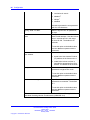
DC power supply accessories
The DC power supply shipment contains hardware accessories. Use the
following checklist to verify the contents of the 8004DC shipping container.
Table 1
8004DC power supply shipping accessories
Check
Accessory
Use to
Two 2-hole crimp
lug terminals with
attached tubing
(8004)
Connect the positive
and negative power
inputs
One 1-hole crimp
lug terminal with
attached tubing
Connect the ground
stud
5 nuts
Connect all leads
5 lock washers
Connect all leads
1 washer
Connect the ground
stud
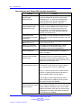
Use the following checklist to verify the contents of the 8005DC shipping
container.
Table 2
8005DC power supply shipping accessories
Check
Accessory
Use to
Three 2-hole crimp
lug terminals with
attached tubing
Connect the positive
and negative power
inputs
Nortel Ethernet Routing Switch 8600
Quick Start
NN46205-310 02.01 Standard
30 May 2008
Copyright © 2008 Nortel Networks
.
Safety precautions 27
Check
Accessory
Use to
6 nuts
Connect all leads
6 lock washers
Connect all leads
2 washers
Connect the ground
stud
Safety precautions
This section describes the safety precautions which are vital for handling
and installing the Ethernet Routing Switch 8600.
Safety precautions navigation
•
•
•
•
“Personal safety” (page 27)
“Module safety” (page 28)
“Cable and connector safety” (page 28)
“Electrostatic discharge safety” (page 29)
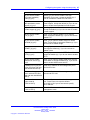
Personal safety
For your safety, review the following personal safety warnings before
working with the Ethernet Routing Switch 8600.
DANGER
Risk of injury by fan blades
When removing the fan module, do not put your hands into the
opening because of the spinning fan blades in the adjacent fan
modules.
WARNING
Risk of personal injury
Grasp the fan tray at the middle of the front panel, and be
careful to keep your fingers out of the fan blades.
DANGER
Risk of injury by electric shock
The electrical connector at the rear of the slot poses a risk of
electrical shock.
Nortel Ethernet Routing Switch 8600
Quick Start
NN46205-310 02.01 Standard
30 May 2008
Copyright © 2008 Nortel Networks
.
28 Installation preparation
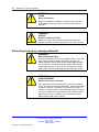
WARNING
Risk of eye injury by laser
Fiber optic equipment can emit laser or infrared light that can
injure your eyes. Never look into an optical fiber or connector
port. Always assume that fiber optic cables are connected to a
light source.
Module safety
Use the following general practices to prevent the equipment damage
when working with the Ethernet Routing Switch 8600.
•
Always wear an antistatic wrist strap that is connected to an
Electrostatic discharge (ESD) grounding jack when handling modules.
•
•
Always set modules on appropriate antistatic material.
•
Do not leave slots open. Fill all the slots with modules, or use slot
covers to maintain safety compliance, proper cooling, and EMI
containment in the chassis.
•
Ensure your environment meets the requirements for temperature,
humidity, and cleanliness.
•
Replace the 8010co chassis air filter regularly (approximately every
three months) to maintain proper cooling and airflow.
For instructions to replace the 8010co chassis air filter, see Nortel
Ethernet Routing Switch 8600 Routine Maintenance, NN46205-312.
•
Do not overtighten thumb screws or lug nuts. Tighten screws and nuts
until snug plus a quarter turn. If you use a power tool to tighten screws,
use a low torque setting (2 to 3 inches per pound [in./lb]).
Handle modules using the faceplate. Do not touch pins or electrical
connections.
Cable and connector safety
Use the following instructions to safeguard cables and connectors while
working with the Ethernet Routing Switch 8600.
•
Support cables to prevent stress on connectors. If the Ethernet Routing
Switch 8600 has a high cable-density configuration, install additional
cable-management equipment.
•
Do not exceed the bend radius recommended for the cable type
installed.
•
Fiber optic cables and connectors require special care.
Nortel Ethernet Routing Switch 8600
Quick Start
NN46205-310 02.01 Standard
30 May 2008
Copyright © 2008 Nortel Networks
.
Safety precautions 29
— Protect connectors with rubber safety plugs when cables are not
inserted.
— Follow appropriate fiber-cleaning procedures to install or replace
cables.
•
Do not exceed the bend radius recommended for fiber optic cables.
The acceptable bend radius for fiber optic cable is ten times
its diameter, or 2.5 to 5 cm (1 to 2 in.). Anything less than the
recommendation can cause a loss of integrity during data transmission.
It is difficult to diagnose loss of integrity because of incorrect bend
radius.
Electrostatic discharge safety
Electrostatic discharge (ESD) is the transfer of charge between objects at
different electrical potentials. ESD can change the electrical characteristics
and degrade or destroy a semiconductor device. ESD can also disrupt
the normal operation of an electronic system by causing equipment
malfunction or failure.
To dissipate or neutralize electrostatic charges, use proper grounding and
conductive or dissipative materials.
CAUTION
Risk of equipment damage
To prevent damage from electrostatic discharge, always wear
an antistatic wrist strap connected to an electrostatic discharge
(ESD) jack.
Proper antistatic packaging effectively shields products from electrostatic
charges and reduces the charge generation caused by product movement
within the container.
Nortel Ethernet Routing Switch 8600
Quick Start
NN46205-310 02.01 Standard
30 May 2008
Copyright © 2008 Nortel Networks
.
30 Installation preparation
Nortel Ethernet Routing Switch 8600
Quick Start
NN46205-310 02.01 Standard
30 May 2008
Copyright © 2008 Nortel Networks
.
31
.
Installation
This chapter contains installation instructions for the Ethernet Routing
Switch 8000 series chassis.
Navigation
•
•
•
“Unpacking the chassis” (page 32)
•
•
•
•
•
•
•
•
•
•
•
•
“Installing the 8010co chassis in a 19-inch two-post rack” (page 36)
“Removing a power filler panel” (page 33)
“Installing an Ethernet Routing Switch 8003, 8006, or 8010 chassis into
a rack” (page 34)
“Installing the 8003, 8006, and 8010 chassis cable guides” (page 37)
“Installing the top cable-management bracket” (page 38)
“Installing the side cable-management brackets” (page 39)
“Grounding the 8010co chassis” (page 40)
“Installing a module” (page 41)
“Installing AC power modules” (page 43)
“Installing DC power modules” (page 44)
“Installing a breaker interface panel” (page 49)
“Installing a PCMCIA software card” (page 49)
“Starting the system” (page 49)
“Verifying a successful installation” (page 51)
Nortel Ethernet Routing Switch 8600
Quick Start
NN46205-310 02.01 Standard
30 May 2008
Copyright © 2008 Nortel Networks
.
32 Installation
Unpacking the chassis
Unpack the shipping container to ensure the chassis and all accessories
are included and undamaged.
Nortel Ethernet Routing Switch 8600
Quick Start
NN46205-310 02.01 Standard
30 May 2008
Copyright © 2008 Nortel Networks
.
Removing a power filler panel
33
Procedure steps
Step
Action
1
Remove the equipment from the shipping container and place
the chassis on antistatic material.
2
Check all items for damage.
ATTENTION
If the equipment is damaged, contact your Nortel sales
representative.
3
Use the following chassis shipping accessories checklist to verify
that the shipping container includes all contents.
Check
Accessory
Use to
Bracket kit: two
rack-mounting brackets
and Phillips-head screws.
Support the chassis in an
equipment rack.
Screw package
Mount the chassis in an
equipment rack.
Side cable-management
bracket: two brackets for
the 8010 chassis and one
bracket for the 8006 and
8003 chassis
Manage network interface
cables.
Rubber footpads
Keep the chassis from
slipping when mounting
on a flat surface.
Console cable with built-in
adapter.
Connect an optional
management console to
the chassis. Each cable
end has a female DB9
and a DB25 connector.
Cable guide
Keep cable clusters
fastened and out of the
way, but accessible for
maintenance.
--End--
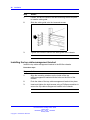
Removing a power filler panel
A power filler panel maintains the proper cooling airflow in the Ethernet
Routing Switch 8600 chassis. You must remove the power filler panel from
the power bay when you install a power supply in a bay for the first time
Nortel Ethernet Routing Switch 8600
Quick Start
NN46205-310 02.01 Standard
30 May 2008
Copyright © 2008 Nortel Networks
.
34 Installation
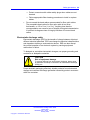
Procedure steps
Step
Action
1
Use a Phillips screwdriver to loosen the two screws that fasten
the filler panel to the chassis.
2
Pull the filler panel away from the slot as shown in the following
figure.
--End--
Installing an Ethernet Routing Switch 8003, 8006, or 8010 chassis
into a rack
Install an Ethernet Routing Switch 8003, 8006, or 8010 chassis in a
standard equipment rack (19-inch).
Prerequisites for installing an Ethernet Routing Switch 8003, 8006, or
8010 chassis into a rack
•
Remove any filler panels before you install the chassis to decrease the
weight during installation.
Procedure steps
Step
Action
1
Hold each rack-mounting bracket to the sides of the chassis, and
align the screw holes.
Nortel Ethernet Routing Switch 8600
Quick Start
NN46205-310 02.01 Standard
30 May 2008
Copyright © 2008 Nortel Networks
.
Installing an Ethernet Routing Switch 8003, 8006, or 8010 chassis into a rack
2
35
Attach the brackets to the chassis using the supplied
Phillips-head screws.
WARNING
Risk of personal injury
It requires two people to lift a fully-loaded chassis. To
prevent injury, keep your back straight and lift with
your legs.
An Ethernet Routing Switch 8010 chassis weighs
approximately 101 kg (225 lbs).
An Ethernet Routing Switch 8006 chassis weighs
approximately 77 kg (170 lbs).
An Ethernet Routing Switch 8003 chassis weighs
approximately 49.5 kg (110 lbs).
3
Hold the chassis in position and align the flanged end of each
mounting rail with the two holes on each side of the vertical rack
support.
Nortel Ethernet Routing Switch 8600
Quick Start
NN46205-310 02.01 Standard
30 May 2008
Copyright © 2008 Nortel Networks
.
36 Installation
4
Insert and tighten the rack-mounting screws with a Phillips
screwdriver.
--End--
Installing the 8010co chassis in a 19-inch two-post rack
Install the 8010co chassis in a 19-inch two-post rack.
Prerequisites
•
Verify that you have the following tools and materials:
— 12 Phillips-head screws
— 1 Phillips screwdriver
Procedure steps
Step
Action
1
Place the installation shelf at the bottom of the rack and inside
the rails.
2
Hold the installation shelf in position and align the shelf mounting
rail with the two holes on each side of the vertical rack support.
3
Insert a Phillips-head screw through each installation shelf
mounting hole and into the corresponding hole in the rack.
Nortel Ethernet Routing Switch 8600
Quick Start
NN46205-310 02.01 Standard
30 May 2008
Copyright © 2008 Nortel Networks
.
Installing the 8003, 8006, and 8010 chassis cable guides
37
4
Add a hex nut to each screw and tighten using a hex wrench.
5
Tighten each screw using a Phillips-head screwdriver.
6
If the holes in the rack vertical supports require clip nuts, insert a
clip nut into each of the 12 locations.
7
Lift the 8010co chassis onto the installation shelf.
WARNING
Risk of personal injury
It requires three people to lift the 8010co chassis. To
make the chassis lighter, remove the modules and
power supplies before you lift it.
8
Hold the 8010co chassis in position and align the flanged end of
the chassis mounting rail with the six holes on each side of the
vertical rack support.
Make sure the hole pairs on each side of the vertical support
match horizontally.
9
Tighten each screw using a Phillips-head screwdriver.
--End--
Installing the 8003, 8006, and 8010 chassis cable guides
Install the 8003, 8006, and 8010 chassis cable guides to fasten the cable
clusters and keep them out of the way.
ATTENTION
Ensure the cable clusters are accessible for maintenance.
Procedure steps
Nortel Ethernet Routing Switch 8600
Quick Start
NN46205-310 02.01 Standard
30 May 2008
Copyright © 2008 Nortel Networks
.
38 Installation
Step
Action
1
Loosen, but do not remove, the rack-mounting screws required
to install a cable guide.
2
Slide the cable guide onto the loosened screws.
3
Tighten the screws to secure the cable guide to the chassis.
--End--
Installing the top cable-management bracket
Install the top cable-management bracket to the 8010co chassis.
Procedure steps
Step
Action
1
Align the mounting retainers on the inside of the top
cable-management bracket with the holes on the front of the
chassis.
2
Push the sides of the top cable-management bracket into place.
3
Insert and tighten the eight screws using a Phillips screwdriver to
secure the top cable-management bracket to the chassis.
--End--
Nortel Ethernet Routing Switch 8600
Quick Start
NN46205-310 02.01 Standard
30 May 2008
Copyright © 2008 Nortel Networks
.
Installing the side cable-management brackets
Procedure job aid: Installing the cable-management brackets
Installing the side cable-management brackets
Install the side cable-management brackets to each side of the 8010co
chassis.
Procedure steps
Step
Action
1
Align the slots on the side cable-management bracket with the
rods in the chassis.
2
Push the bracket into place.
For more information, see “Procedure job aid: Installing the
cable-management brackets” (page 39)
--End--
Nortel Ethernet Routing Switch 8600
Quick Start
NN46205-310 02.01 Standard
30 May 2008
Copyright © 2008 Nortel Networks
.
39
40 Installation
Grounding the 8010co chassis
Ground the 8010co chassis to avoid electrical hazard and ensure optimal
performance.
ATTENTION
Nortel recommends grounding the 8010co chassis before you connect power
cables or network cables to your switch.
Prerequisites
•
Verify that you have the following tools and materials:
— One single-hole cable lug that fits over one of the grounding studs.
— A nut and locking washer for the grounding stud
— A 6-AWG grounding wire long enough to connect to the ground
point
— A 7/16-inch hex wrench to fasten the hardware in the correct order
Procedure steps
Step
Action
1
Locate the shelf grounding point on the rack.
The rack grounding point is a grounding strip located on the
back, base, top, or side.
ATTENTION
The rack grounding strip can look different than the one shown in
“Procedure job aid: Grounding the 8010co chassis” (page 41) the
procedure job aid.
2
Attach the lug ends of the chassis ground cables to the rack
grounding strip using a 7/16-inch hex wrench to fasten the
hardware in the correct order.
For more information, see “Procedure job aid: Grounding the
8010co chassis” (page 41).
--End--
Nortel Ethernet Routing Switch 8600
Quick Start
NN46205-310 02.01 Standard
30 May 2008
Copyright © 2008 Nortel Networks
.
Installing a module
41
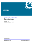
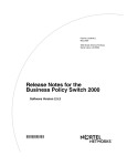
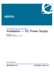
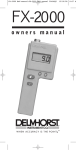
Procedure job aid: Grounding the 8010co chassis
Figure 1
Location of ground studs on a 8010co chassis rear panel
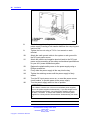
Installing a module
Install Ethernet Routing Switch 8600 modules to provide communications
interfaces for switching and routing operations.
Nortel Ethernet Routing Switch 8600
Quick Start
NN46205-310 02.01 Standard
30 May 2008
Copyright © 2008 Nortel Networks
.
42 Installation
ATTENTION
You can install an Ethernet Routing Switch 8600 module with the power on or
off.
Procedure steps
Step
Action
1
Locate the slot where you want to install the module.
2
Remove the power filler panel.
For instructions, see “Removing a power filler panel” (page 33).
3
Extend the insert and extract levers away from the front of the
module.
4
Slide the module into the slot, using the module guides, until the
connector panel touches the chassis back panel.
5
Rotate the insert and extract levers to seat the module
backplane connectors.
6
Tighten the two captive screws to secure the module to the
chassis using a Phillips screwdriver.
See “Procedure job aid: Installing a module” (page 43) for
installing a module in various chassis.
7
After you install the modules, you can connect console
equipment and network cables.
--End--
Nortel Ethernet Routing Switch 8600
Quick Start
NN46205-310 02.01 Standard
30 May 2008
Copyright © 2008 Nortel Networks
.
Installing AC power modules
43
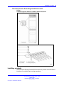
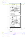
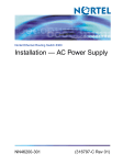
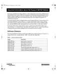
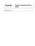
Procedure job aid: Installing a module
Figure 2
Installing a module in a 8010co chassis
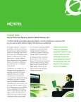
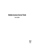
Figure 3
Installing a module in a 8003, 8006, and 8010 chassis
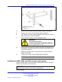
Installing AC power modules
Install AC power modules in the left-most bay to supply AC power to the
chassis.
ATTENTION
The 8006, 8010, and 8010co chassis have three power supply bays that are
numbered 1, 2, and 3 from left to right as viewed from the front of the chassis.
The 8003 chassis has 2 power supply bays that are numbered 1 and 2 from left
to right.
Nortel Ethernet Routing Switch 8600
Quick Start
NN46205-310 02.01 Standard
30 May 2008
Copyright © 2008 Nortel Networks
.
44 Installation
Prerequisites
Ensure the filler panel or cover from the power bay is removed. To remove
the filler panel, see “Removing a power filler panel” (page 33).
Procedure steps
Step
Action
1
Grasp the handle of the new power supply and push the power
supply firmly into the bay.
2
Tighten the retaining screws until the power supply is firmly
seated.
3
Connect the power cord to the power supply and to an AC power
outlet that is connected to a circuit with no other equipment
connections.
--End--
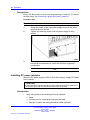
Installing DC power modules
Install the DC power supply module in the leftmost bay to supply DC power
to the chassis.
ATTENTION
The 8006 and 8010 chassis have three power supply bays that are numbered 1,
2, and 3 from left to right as viewed from the front of the chassis.
Prerequisites
•
Verify that you have the following tools and materials:
— Cable
— Crimping tool for crimping the lugs onto the cable
— Heat gun to shrink the tubing around the cable (optional)
Nortel Ethernet Routing Switch 8600
Quick Start
NN46205-310 02.01 Standard
30 May 2008
Copyright © 2008 Nortel Networks
.
Installing DC power modules
45
— A 7/16-inch hex wrench
— Phillips screwdriver
•
Ensure the filler panel or cover is removed from the power bay. To
remove the filler panel, see “Removing a power filler panel” (page 33).
ATTENTION
Nortel does not supply the cables for connecting the DC power supply to the DC
input power source. Select cables that comply with the electrical code of the
country where you use the DC power supply.
Procedure steps
Step
Action
1
Make sure that the power switch is turned off.
2
Grasp the handle of the new power supply and push it partway
into the bay, leaving the terminal block at the side of the power
supply exposed.
3
Remove the screw that secures the plastic safety cover to the
power supply using a Phillips screwdriver.
4
Remove the cover and set it aside.
5
Record the positions of the ground stud and of the positive and
negative power inputs.
ATTENTION
Make sure the +DC cable is always connected to the positive terminal
and that the -DC cable is always connected to the negative terminal.
DANGER
Risk of injury by electric shock
Make sure that the DC power source is off by
switching off the circuit breaker or disconnecting at
the remote end before you connect the terminal leads
to the power supply.
Nortel Ethernet Routing Switch 8600
Quick Start
NN46205-310 02.01 Standard
30 May 2008
Copyright © 2008 Nortel Networks
.
46 Installation
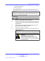
6
Attach the earth ground lead to the ground stud on the power
supply. Use the washers in the following order:
•
•
•
•
flat washer
crimp lug
lock washer
hex nut
Nortel Ethernet Routing Switch 8600
Quick Start
NN46205-310 02.01 Standard
30 May 2008
Copyright © 2008 Nortel Networks
.
Installing DC power modules
7
Attach the positive voltage lead to the positive terminal on the
power supply, inserting a lock washer between the crimp lug and
each hex nut.
Nortel Ethernet Routing Switch 8600
Quick Start
NN46205-310 02.01 Standard
30 May 2008
Copyright © 2008 Nortel Networks
.
47
48 Installation
8
Attach the negative voltage lead to the negative terminal on the
power supply, inserting a lock washer between the crimp lug and
each hex nut.
9
Tighten the hex nut using a 7/16 in. hex wrench on each
terminal.
10
Attach the earth ground cable to the system or rack ground for
the DC input power source.
11
Attach the positive and negative terminal leads to the DC input
power source according to the safety and technical specifications
for your 48 V power distribution system.
12
Replace the plastic safety cover on the power supply using a
Phillips screwdriver.
13
Firmly slide the power supply all the way into the bay.
14
Tighten the retaining screws until the power supply is firmly
seated.
15
Turn the DC input power source on, or reset the power source
circuit breaker, to provide power to the power supply.
16
Turn the power supply switch to the on position.
ATTENTION
If the chassis contains two or three non-redundant power supplies,
turn on the power supplies simultaneously. If you wait longer to turn
on the second power supply, one of the power supplies can turn
off within 7 seconds. To correct this condition, turn off the power
supplies for a short period of time and then simultaneously turn them
on.
--End--
Nortel Ethernet Routing Switch 8600
Quick Start
NN46205-310 02.01 Standard
30 May 2008
Copyright © 2008 Nortel Networks
.
Starting the system
49
Cable preparation
Prepare cables for connecting the DC power supply.
Procedure steps
Step
Action
1
Strip 0.81 in. (2.1 cm) of insulation from the ends of the cables.
2
Crimp the lugs onto the cables using a standard crimping tool.
WARNING
Failure to properly crimp the lugs onto the cables
constitutes a safety hazard.
3
If necessary, use a heat gun to shrink the tubing around the
cable.
--End--
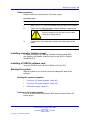
Installing a breaker interface panel
For more information on installing a breaker interface panel (BIP),
see Installing the Breaker Interface Panel for the 8010co Chassis ,
(NN46205-313).
Installing a PCMCIA software card
Insert the PCMCIA card into the PCMCIA slot of the CPU.
Starting the system
Start the system to run a set of internal self-diagnostic tests for all
modules.
Starting the system navigation
•
•
•
“Turning on AC power supplies” (page 49)
“Turning on DC power supplies” (page 50)
“LED power supply” (page 51)
Turning on AC power supplies
Turn on an Ethernet Routing Switch 8000 Series chassis with an AC
power supply.
Nortel Ethernet Routing Switch 8600
Quick Start
NN46205-310 02.01 Standard
30 May 2008
Copyright © 2008 Nortel Networks
.
50 Installation
Procedure steps
Step
Action
1
Verify the AC power cords are connected to AC power outlets.
2
Turn each AC power supply switch to the on position
simultaneously. Do not operate the 8010co chassis with only one
power supply.
ATTENTION
If the chassis contains two or three power supplies, turn on the
power supplies simultaneously. If you wait longer to turn on the
second power supply, one of the power supplies can turn off within 7
seconds. To correct this condition, turn off the power supplies for a
short period of time and then simultaneously turn them on.
3
Verify that the power LED on each power supply turns green.
4
Verify that the power supply status LEDs and the fan LED on the
8691SF/CPU or 8692SF/CPU modules turn green.
5
Verify that air flows from the cooling fans through the chassis
vents.
ATTENTION
The red fan tray fail LED may light briefly while the fans power to
operational speed.
--End--
Turning on DC power supplies
Step
Action
1
Turn the power switch on each DC power supply to the on
position. It is not necessary to remove the bezel to turn the
switch on.
ATTENTION
If the chassis contains two or three power supplies, turn on the
power supplies simultaneously. If you wait longer to turn on the
second power supply, one of the power supplies can turn off within 7
seconds. To correct this condition, turn off the power supplies for a
short period of time and then simultaneously turn them on.
2
Verify that the power output LED for each power supply turns
green.
3
Verify that the power supply status LEDs and the fan LED on the
8691SF/CPU or 8692SF/CPU modules turn green.
Nortel Ethernet Routing Switch 8600
Quick Start
NN46205-310 02.01 Standard
30 May 2008
Copyright © 2008 Nortel Networks
.
Verifying a successful installation
51
ATTENTION
The red fan tray fail LED may light briefly while the fans power to
operational speed.
--End--
LED power supply
After you turn on the Ethernet Routing Switch 8000 Series, each module
automatically initiates a diagnostic test to verify proper module function.
If the power supply LED remains off, do the following:
Procedure steps
Step
Action
1
Turn the power switch on each power supply to the off position.
2
Wait 1 minute.
3
Turn the power switch on each power supply to the on position.
--End--
Verifying a successful installation
• The following list describes a successful starting sequence for an
Ethernet Routing Switch.
— When power is applied to the Ethernet Routing Switch 8000, the
green LED on each power supply and fan tray or cooling module
turns on, and the Online LED for each module is amber.
— Each module initiates a self-test, during which time the port and
module LEDs display various patterns to indicate the progress of
the self-test.
— Upon successful completion of the self-test (within 2 or 3 minutes
after power is applied to a fully loaded chassis), the module Online
LED transitions from amber to green.
— After 1 minute of operation, the fan tray Pass LED lights remain
green.
— If the LEDs on the modules light in this sequence, your installation
is successful. Contact your network administrator to verify that the
Ethernet Routing Switch 8000 is connected to the network.
Nortel Ethernet Routing Switch 8600
Quick Start
NN46205-310 02.01 Standard
30 May 2008
Copyright © 2008 Nortel Networks
.
52 Installation
Nortel Ethernet Routing Switch 8600
Quick Start
NN46205-310 02.01 Standard
30 May 2008
Copyright © 2008 Nortel Networks
.
53
.
Configuration
This chapter contains configuration instructions for Ethernet Routing
Switch 8600.
Navigation
•
•
•
•
•
•
•
•
“Connecting a modem using the CLI” (page 53)
“Connecting a modem using the NNCLI” (page 56)
“Connecting a VT-100 terminal or PC for local access” (page 58)
“Setting system date and time using the CLI” (page 59)
“Setting system date and time using the NNCLI” (page 59)
“Changing passwords using the CLI” (page 22)
“Changing passwords using the NNCLI” (page 22)
“Configuring the system using the setup utility” (page 65)
Connecting a modem using the CLI
This section describes how to connect a modem to the modem port on
a module. You can access the CLI through a modem connection to the
Ethernet Routing Switch 8690SF, 8691SF/CPU, or 8692SF/CPU modules.
The modem port is a DTE device is operating at:
•
•
•
•
9600 baud rate
8 data bits
no parity
one stop bit
ATTENTION
Nortel recommends to use the default settings for the Modem port for most
modem installations.
Nortel Ethernet Routing Switch 8600
Quick Start
NN46205-310 02.01 Standard
30 May 2008
Copyright © 2008 Nortel Networks
.
54 Configuration
Because the modem port will receive Data Set Ready (DSR) and Clear To
Send (CTS) signals before transmitting, the DSR and CTS control lines are
required in the cables. The modem port does not support inbound flow
control; therefore, the port does not turn on and off control lines to indicate
that the input buffer is full.
Before connecting a modem to an Ethernet Routing Switch you may need
to configure the modem port using another type of CLI connection.
To configure the modem port using the Ethernet Routing Switch CLI,
complete the steps in the following procedure.
Prerequisites
•
You need a DTE-to-DCE cable (straight or transmit cable) to connect
the Nortel Ethernet Routing Switch 8600 to the modem.
•
You must configure your client dial-up settings to establish the
connection to the modem.
Procedure steps
Step
Action
1
Configure the modem using the following command:
config bootconfig sio modem
Now you can enter options for this command level without
retyping the first part of the command.
2
Configure port parameters based on the modem requirements:
•
baud <rate>
•
8databits <true|false>
•
mode <ascii|slip|ppp>
For information about the configuration requirements of your
modem, see the documentation shipped with the modem.
ATTENTION
Nortel recommends that before you configure SLIP or PPP modes,
you become familiar with these protocols.
3
If you assign the port mode to slip, configure the following
parameters:
•
•
slip-compression <true|false>
slip-rx-compression <true|false>
Nortel Ethernet Routing Switch 8600
Quick Start
NN46205-310 02.01 Standard
30 May 2008
Copyright © 2008 Nortel Networks
.
Connecting a modem using the CLI
4
55
If you assign the port mode to ppp, configure the following
parameters:
•
•
•
•
mtu <bytes>
my-ip <ipaddr>
peer-ip <ipaddr>
pppfile <file>
5
Turn off echo mode and return code messaging on the modem.
6
Connect the modem to the modem port.
7
Save the boot configuration.
8
Reboot the switch.
--End--
Variable definitions
Variable
Value
8databits <true|false>
Specifies either 8 (true) or 7 (false) data bits
for each byte for software to interpret. The
default is false.
baud<rate>
Sets the baud rate for the modem. The
default is 9600.
enable <true|false>
True sets the value to 7.
False sets the value to 8. This setting is
default.
ascii
Sets the default setting.
This setting is recommended for most
modem connections.
slip
Sets the port for serial line IP (SLIP)
operation.
ppp
Sets the port for point-to-point protocol
(PPP) operation.
slip-compression
<true|false>
Enables or disables the TCP/IP header
compression. The default is false.
slip-rx-compression
<true|false>
Enables or disables the TCP/IP header
compression on the receive packet. The
default is false.
mtu <bytes>
Sets the maximum transmission unit for the
point-to-point link (0–2048). The default is
zero (0).
my-ip <ipaddr>
Sets the near-end IP address on the
point-to-point link. The default is 0.0.0.0.
Nortel Ethernet Routing Switch 8600
Quick Start
NN46205-310 02.01 Standard
30 May 2008
Copyright © 2008 Nortel Networks
.
56 Configuration
Variable
Value
peer-ip <ipaddr>
Sets the peer IP address on the
point-to-point link. The default is 0.0.0.0.
pppfile <file>
Identifies the file to use for PPP initialization
parameters.
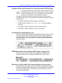
Procedure job aid: DTE-to-DCE straight-through pin assignments
Table 3
DTE-to-DCE straight-through pin assignments
Switch
Modem
Signal
Pin
number
DCE DB-9
pin number
DCE DB-25
pin number
RXD
2
2
3
TXD
3
3
2
DTR
4
4
20
GND
5
5
7
DSR
6
6
6
RTS
7
7
4
CTS
8
8
5
Connecting a modem using the NNCLI
Connect a modem to a Ethernet Routing Switch 8600 to establish a
connection with the switch. To connect a modem to an Ethernet Routing
Switch you may need to set up the modem port using another type of
connection, such as a terminal connection, to the NNCLI.
You can access the NNCLI through a modem connection to the Ethernet
Routing Switch 8690SF, 8691SF/CPU, or 8692SF/CPU modules.
ATTENTION
Nortel recommends that you use the default settings for the modem port for
most modem installations.
Prerequisites
•
You need a DTE-to-DCE cable (straight or transmit cable) to connect
the Nortel Ethernet Routing Switch 8600 to the modem.
•
You must configure your client dial-up settings to establish the
connection to the modem.
•
You must log on to the Global Configuration mode in the NNCLI.
Nortel Ethernet Routing Switch 8600
Quick Start
NN46205-310 02.01 Standard
30 May 2008
Copyright © 2008 Nortel Networks
.
Connecting a modem using the NNCLI 57
Procedure steps
Step
Action
1
Configure port parameters based on the requirements of the
modem by using the following command:
boot config sio modem
For information about the configuration requirements of your
modem, see the documentation shipped with the modem.
ATTENTION
Nortel recommends that before you configure Serial Line IP (SLIP) or
PPP, you become familiar with these protocols.
2
If you assign the port mode to slip, use the following command
to configure other slip parameters:
boot config sio modem [slip-compression]
[slip-rx-compression]
3
If you assign the port mode to ppp, use the following commands
to configure other ppp parameters:
boot config sio modem [mtu <bytes>] [my-ip
<ipaddr>] [peer-ip <ipaddr>] [pppfile <file>]
4
Turn off echo mode and return code messaging on the modem.
5
Connect the modem to the modem port.
6
Save the boot configuration.
7
Optionally, shutdown and reinitialize the port by using the
following command:
boot config sio modem restart
8
Reboot the switch.
--End--
Variable definitions
Variable
Value
8databits
Set number of data bits per byte for
software to interpret.
baud
Set baud rate for the modem.
mode
Set serial port mode.
mtu
Sets point-to-point link maximum
transmission unit.
my-ip
Sets my IP address on point-to-point link.
Nortel Ethernet Routing Switch 8600
Quick Start
NN46205-310 02.01 Standard
30 May 2008
Copyright © 2008 Nortel Networks
.
58 Configuration
Variable
Value
peer-ip
Set peer IP address on point-to-point link.
pppfile
Use the file for PPP initialization
parameters.
restart
Shutdown and re-initialize the port.
slip-compression
Enable TCP/IP header compression.
slip-rx-compression
Enable receive packet TCP/IP header
compression.
my-ip
Sets my IP address on point-to-point link.
Procedure job aid: DTE-to-DCE straight-through pin assignments
Table 4
DTE-to-DCE straight-through pin assignments
Switch
Modem
Signal
Pin
number
DCE DB-9
pin number
DCE DB-25
pin number
RXD
2
2
3
TXD
3
3
2
DTR
4
4
20
GND
5
5
7
DSR
6
6
6
RTS
7
7
4
CTS
8
8
5
Connecting a VT-100 terminal or PC for local access
Connect a VT-100 terminal or a personal computer to the console port on
a 8691SF/CPU or 8692SF/CPU module to establish a local CLI, NNCLI
or Device Manager session.
Prerequisites
•
A serial console cable with a nine-pin receptable connector.
Procedure steps
Step
Action
1
Connect an RS-232 cable to the console port on an
8691SF/CPU or 8692SF/CPU module.
2
Connect the other end of the RS-232 cable to a VT-100 terminal
or PC serial port.
Nortel Ethernet Routing Switch 8600
Quick Start
NN46205-310 02.01 Standard
30 May 2008
Copyright © 2008 Nortel Networks
.
Setting system date and time using the NNCLI
3
Turn on the terminal or PC.
4
Log on to the CLI.
59
--End--
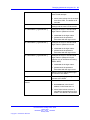
Setting system date and time using the CLI
Set the system date and time using the CLI.
Procedure steps
Action
Set the date of the system by using the following command:
config setdate <MMddyyyyhhmmss>
Procedure job aid: config setdate command sample output
The following is a sample output to verify the config setdate command.
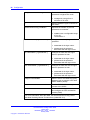
Setting system date and time using the NNCLI
Set the system date and time using the NNCLI.
Prerequisites
•
You must log on to the privExec mode.
Procedure steps
Action
Set the system date by using the following command:
clock set <MMddyyyyhhmmss>
Procedure job aid: clock set command output
The following is a sample output to verify the clock set command .
Nortel Ethernet Routing Switch 8600
Quick Start
NN46205-310 02.01 Standard
30 May 2008
Copyright © 2008 Nortel Networks
.
60 Configuration
Changing passwords using the CLI
Set new passwords for each access level, or change the logon password
for the different switch access.
The Ethernet Routing Switch Switch 8600 ships with default passwords
configured for CLI access. When you use Simple Network Management
Protocol version 3 (SNMPv3), you can change passwords that are in an
encrypted format.
Prerequisites
•
You must have read-write-all privileges to change passwords.
Passwords are saved to a hidden file to maintain security. The
password associated with the user name or logon name is the optional
password parameter.
Procedure steps
Action
Change a password by using the following command:
config cli password
Variable definitions
Use the data in the following table to use the config cli password
command.
Variable
Value
access level <access level>
<enable|disable>
Allows or blocks this access level.
aging <days>
•
access level is an integer from
2 to 8.
•
enable|disable enables or
disables the chosen access level.
Sets the password age-out time.
•
days is the number of days until
the password expires from 1 to
365.
Nortel Ethernet Routing Switch 8600
Quick Start
NN46205-310 02.01 Standard
30 May 2008
Copyright © 2008 Nortel Networks
.
Changing passwords using the CLI
default-lockout-time <secs>
Changes the default lockout time after
three invalid attempts.
•
secs is the lockout time in seconds
from 60 to 6500. The default is 60
seconds.
info
Shows the current level parameter
settings and the next level directories.
l1 <username> [ <password> ]
Changes the Layer 1 read and write
logon name or password or both.
•
•
l2 <username> [ <password> ]
l3 <username> [ <password> ]
username is the logon name
password is the password
associated with the logon name.
Changes the Layer 2 read and write
logon name or password or both.
•
•
username is the logon name.
password is the password
associated with the logon name.
Changes the Layer 3 read and write
logon name or password or both
(applies only to the Ethernet Routing
Switch 8600).
•
•
username is the logon name.
password is the password
associated with the logon name.
l4admin <username>
Sets the Layer 4 Administrator logon
to connect to the WSM.1
l4oper <username>
Sets the Layer 4 Operator logon to
connect to the WSM.1
lockout-time <HostAddress>
<secs>
Sets the Host lockout time.
•
HostAddress is the Host IP
address in the format a.b.c.d.
•
secs is the lockout-out time in
seconds for passwords from 60 to
65000. The default is 60 seconds.
Nortel Ethernet Routing Switch 8600
Quick Start
NN46205-310 02.01 Standard
30 May 2008
Copyright © 2008 Nortel Networks
.
61
62 Configuration
min-passwd-len <integer>
Sets the minimum length for
passwords in high-secure mode.
•
integer is a range from a
minimum of 10 to 20.
oper <username>
Sets the Operator logon to connect to
the WSM.1
password-history <number>
Specifies the number of previous
passwords to remember.
•
ro <username> [ <password> ]
Changes the read-only logon and/or
password.
•
•
rw <username> [ <password> ]
username is the logon name.
password is the password
associated with the logon name.
Changes the read and write logon
name or password or both.
•
•
rwa <username> [ <password> ]
number uses a configurable range
of 3 to 32.
The default is 3.
username is the logon name.
password is the password
associated with the logon name.
Changes the read and write all logon
name or password or both.
•
•
username is the logon name.
password is the password
associated with the logon name.
slboper <username>
Sets the server load balancing (SLB)
Operator login to connect to the Web
Switch Module (WSM).1
slbadmin <username>
Sets the SLB Administrator logon to
connect to the WSM.1
ssladmin <username>
Sets the ssladmin logon to connect to
and configure the SSL acceleration
module (SAM).
1
For more information about the WSM, see Nortel Ethernet Routing Switch
8600 Web Switching Module Fundamentals, (NN46205-314).
Nortel Ethernet Routing Switch 8600
Quick Start
NN46205-310 02.01 Standard
30 May 2008
Copyright © 2008 Nortel Networks
.
Changing passwords using the NNCLI
63
Changing passwords using the NNCLI
Set new passwords for each access level, or change the logon or
password for various access levels of the switch.
The Ethernet Routing Switch 8600 ships with default passwords set for
access to the NNCLI. When using Simple Network Management Protocol
version 3 (SNMPv3), you can change passwords that are in encrypted
format.
Prerequisites
•
You must have read-write-all privileges to change passwords. For
security, passwords are saved to a hidden file.
•
You must log on to the global configuration mode.
Procedure steps
Step
Action
1
Change a password by using the following command:
cli password <word> <access-level>
2
Configure password options by using the following command:
password aging-time [day <1-365>] [default-lockout-time
<60-65 000>] [min-passwd-len <10-20>] [password-history
<3-32>]
--End--
Variable definition
Use the data in the following table to use the password commands.
Variable
Value
access level
Allows or blocks this access level. The
available access levels are:
•
•
•
•
•
•
•
•
l4admin 1
l4oper1
layer1 <word>
layer2
layer3 <word>
oper1
read-only <word>
read-write <word>
Nortel Ethernet Routing Switch 8600
Quick Start
NN46205-310 02.01 Standard
30 May 2008
Copyright © 2008 Nortel Networks
.
64 Configuration
•
•
•
•
read-write-all <word>
slbadmin1
slboper1
ssladmin
<word> represents the new password
with 0 to 20 characters.
aging-time <1-365>
Sets the age-out time for passwords,
in days.
default-lockout-time <60-65
000>
Changes the default lockout time after
three invalid attempts. Sets the lockout
time in seconds and is in the range
of 60 to 65 000. The default is 60
seconds.
To set this option to the default value,
use the default operator with the
command.
lockout <WORD 0-64> time
<60-65000>
min-passwd-len <10-20>
Sets the Host lockout time.
•
word is the Host Internet Protocol
(IP) address in the format a.b.c.d.
•
time is the lockout-out time in
seconds for passwords from 60 to
65 000. The default is 60 seconds.
Sets the minimum length for
passwords in high-secure mode.
To set this option to the default value,
use the default operator with the
command.
password-history <3-32>
Specifies the number of previous
passwords to remember. The default
is 3.
To set this option to the default value,
use the default operator with the
command.
1
For more information about the WSM, see Nortel Ethernet Routing Switch
8600 Web Switching Module Fundamentals, (NN46205-314).
Nortel Ethernet Routing Switch 8600
Quick Start
NN46205-310 02.01 Standard
30 May 2008
Copyright © 2008 Nortel Networks
.
Configuring the system using the setup utility
65
Configuring the system using the setup utility
Use the setup utility for the initial configuration of the switch. The setup
utility uses a series of questions to guide you through the configuration
process.
ATTENTION
Answer each question, or accept the default by pressing Enter. Each question
includes the default value in brackets and the acceptable parameter options in
parenthesis.
Procedure steps
Step
Action
1
Power up the system.
2
Connect through the console and logon as a default user using
the following command:
install
ATTENTION
You must connect to the master CPU to use the install script.After
running the setup utility, remember to reboot the switch.
A Welcome to the Ethernet Routing Switch 8000 Setup Utility
message appears stating you are starting initial configuration of
the switch. The data is stored in the /flash/boot.cfg and runtime
configuration flash/config.config files.
3
If you want to continue, type
y.
4
Follow the setup utility prompts.
See “Procedure job aid: Setup Utility prompt descriptions” (page
66).
5
Restart the switch.
ATTENTION
You can use a default password to log on if the switch reboots
without any previously configured password, and the high secure
(hsecure) mode is enabled. however, you will be prompted to change
the password
For more information about the secure mode, see Security,
NN46205-601.
--End--
Nortel Ethernet Routing Switch 8600
Quick Start
NN46205-310 02.01 Standard
30 May 2008
Copyright © 2008 Nortel Networks
.
66 Configuration
Procedure job aid: Setup Utility prompt descriptions
Prompt
Action
Please provide primary
config-file path
[/flash/config.cfg]:
Press Enter to accept the default (/flash/config.cfg),
or enter a different file location for the primary
configuration file. To store the configuration file
on the PCMCIA card, use /pcmcia/config.cfg.
Specifying the path to the file is optional.
Please provide
primary image-file path
[flash/p80a41xx.img]:
Press Enter to accept the default (/flash/p80a4
1xx.img), or enter a different file location for the
primary image file. Specifying the path to the
file is optional. If the runtime image resides on
a PCMCIA card, you must specify the path (for
example /pcmcia/filename).
Please add system
prompt [Ethernet Routing
Switch-8606]:
Press Enter to accept the default (Ethernet Routing
Switch-8606), or enter a different string of up to 20
characters.
Please select CPU
Master slot (5/6) [5]:
Press Enter to accept the default (5), or specify 6
for the master CPU slot.
Master CPU mgmt port:
autonegotiation [n] (y/n)?
Press Enter to accept the default(n), or enter
y to indicate that you want the master CPU
management port to use autonegotiation.
speed (10/100) [10]:
Press Enter to accept the default (10 Mbps), or
specify 100 Mbps.
Do you want to enable
automatic savetostandby
mode [n] (y/n)?
Press Enter y if you want the boot and runtime
configuration files to be saved on the backup
CPU.Press Enter to accept the default (n), if you
want the boot and runtime configuration files to be
saved only on the primary CPU.
Do you want to enable
m-mode support [n] (y/n)?
Press Enter y if you want the chassis to run in 128
K or M mode. Press Enter to accept the default
(n), if you want it to run in 32 K mode only.
To run in 128 K mode, the CPU module must be
an 8691 or higher and the switch must have at
least one 8600 module (128 K module).
If you enable m-mode support and you have a
mixed configuration of modules, the E-modules
and classic modules are disabled.
Do you want to enable
enhanced operation mode
support [n] (y/n)?
Enter y if you want to enable enhanced operation
mode. Accept the default (n), if you do not want to
enable enhanced operation mode. If you enable
enhanced operation mode and you have a mixed
configuration of modules, the classic modules (Eor M-modules) are disabled.
Nortel Ethernet Routing Switch 8600
Quick Start
NN46205-310 02.01 Standard
30 May 2008
Copyright © 2008 Nortel Networks
.
Configuring the system using the setup utility
Prompt
Action
Do you want to enable
CPU High Availability
mode [n] (y/n)?
Specify y if you want to enable CPU high
availability (HA) mode. Accept the default (n), if
you do not want to enable CPU HA mode.
Do you want to enable
vlan-optimization-mode
support [n] (y/n) ?
Specify y if you want to enable vlan-optimizationmode support. Accept the default (n) if you do not
want to enable vlan-optimization-mode support.
Do you want to enable
r-mode support [n] (y/n) ?
Specify y if you want to enable r-mode support.
Accept the default (n) if you do not want to enable
r-mode support.
Do you want to enable
FTP [n] (y/n)?
Enter y if you want to enable FTP for remote
users. Accept the default (n), if you do not want to
enable FTP.
Do you want to enable
RLOGIN [n] (y/n)?
Enter y if you want to enable Rlogin for remote
users. Press Enter to accept the default (n), if you
do not want to enable Rlogin.
Do you want to enable
TELNET [n] (y/n)?
Enter y if you want to enable Telnet. Press Enter
to accept the default (n), if you do not want to
enable Telnet.
Do you want to enable
TFTP [n] (y/n)?
Enter y if you want to enable TFTP. Press Enter to
accept the default (n), if you do not want to enable
TFTP.
Do you want to enable
WEB server service [n]
(y/n)?
Enter y if you want to enable WEB server service.
Press Enter to accept the default (n), if you do not
want to enable WEB server service.
IP Address for mgmt port
in first CPU Slot [192.168.
168.168/255.255.255.0]:
Enter the IP address of the management port in
the first CPU slot.
IP Address for mgmt
port in second CPU Slot
[192.168.168.169/255.255
.255.0]:
Enter the IP address of the management port in
the second CPU slot.
IP Address for
mgmt-virtual-ip
[0.0.0.0/0.0.0.0]:
Enter the IP address of the virtual management
port. Press Enter to accept the default
(0.0.0.0/0.0.0.0) if you do not want to specify
an IP address.
First net mgmt route
[0.0.0.0:0.0.0.0]:
Enter the IP address of the first network
management route.
Nortel Ethernet Routing Switch 8600
Quick Start
NN46205-310 02.01 Standard
30 May 2008
Copyright © 2008 Nortel Networks
.
67
68 Configuration
Prompt
Action
Second net mgmt route
[0.0.0.0:0.0.0.0]:
Enter the IP address of the second network
management route (static route from the network
management port to a device in the network).
For security reasons, the system does not accept
a route to a network that conflicts with the main
nonmanagement routing table, and, therefore,
does not accept a default route of 0.0.0.0.
Third net mgmt route
[0.0.0.0:0.0.0.0]:
Enter the IP address of the third network
management route (static route from the network
management port to a device in the network).
Fourth net mgmt route
[0.0.0.0:0.0.0.0]:
Enter an IP address of the fourth network
management route (static route from the network
management port to a device in the network).
IP address of the default
VLAN
[0.0.0.0/0.0.0.0]:
Enter the IP address of the default virtual LAN
(VLAN).
Do you want to save the
changes
Enter y to save the boot and runtime configuration
files. Press Enter n if you do not want to save your
changes.
[Saving the parameters
will update the files
/flash/boot.cfg and
/flash/config.cfg] (y/n)?
Nortel Ethernet Routing Switch 8600
Quick Start
NN46205-310 02.01 Standard
30 May 2008
Copyright © 2008 Nortel Networks
.
69
.
Translation of safety messages
Fan tray safety warning message
WARNING
Risk of personal injury
Grasp the fan tray at the middle of the front panel, and be
careful to keep your fingers out of the fan blades.
WARNING
AVERTISSEMENT
Risques de blessure corporelle
Saisissez le boîtier du ventilateur au milieu du panneau avant
en veillant à maintenir vos doigts éloignés des pales.
WARNING
WARNUNG
Verletzungsrisiko
Greifen Sie das Gehäuse des Lüfters vorne in der Mitte, und
achten Sie darauf, dass Ihre Finger nicht zwischen die Blätter
des Lüfters geraten.
WARNING
ADVERTENCIA
Riesgo de lesiones
Sostenga la bandeja del ventilador en la mitad del panel
delantero y tenga cuidado de mantener los dedos alejados de
las aspas.
Nortel Ethernet Routing Switch 8600
Quick Start
NN46205-310 02.01 Standard
30 May 2008
Copyright © 2008 Nortel Networks
.
70 Translation of safety messages
WARNING
AVISO
Risco de ferimento
Segure a bandeja do ventilador no meio do painel frontal e
tenha cuidado para não colocar os dedos nas lâminas do
ventilador.
WARNING
AVVISO
Rischio di lesioni personali
Afferrare il vassoio del ventilatore nella parte centrale del
pannello frontale e prestare attenzione a non toccare le lame.
Preventing back injury warning statement
WARNING
Risk of personal injury
It requires two people to lift a fully-loaded chassis. To prevent
injury, keep your back straight and lift with your legs. An
Ethernet Routing Switch 8010 chassis weighs approximately
101 kg (225 lbs). An Ethernet Routing Switch 8006 chassis
weighs approximately 77 kg (170 lbs). An Ethernet Routing
Switch 8003 chassis weighs approximately 49.5 kg (110 lbs).
WARNING
AVERTISSEMENT
Risques de blessure corporelle
Deux personnes sont nécessaires pour soulever un châssis
rempli. Pour éviter tout risque de blessure, gardez le dos droit
et utilisez l’appui de vos jambes pour soulever la charge. Le
châssis d’un commutateur-routeur Ethernet 8010 pèse environ
101 kg. Le châssis d’un commutateur-routeur Ethernet 8006
pèse environ 77 kg. Le châssis d’un commutateur-routeur
Ethernet 8003 pèse environ 49,5 kg.
Nortel Ethernet Routing Switch 8600
Quick Start
NN46205-310 02.01 Standard
30 May 2008
Copyright © 2008 Nortel Networks
.
Preventing back injury warning statement
71
WARNING
WARNUNG
Verletzungsrisiko
Es sind 2 Personen notwendig, um ein voll besetztes Chassis
anzuheben. Zur Vermeidung von Verletzungen halten Sie
beim Heben Ihren Rücken gerade, und heben Sie das Gewicht
aus den Beinen heraus. Das Chassis des Ethernet Routing
Switch 8010 wiegt ungefähr 101 kg (225 lbs). Das Chassis des
Ethernet Routing Switch 8006 wiegt ungefähr 77 kg (170 lbs).
Das Chassis des Ethernet Routing Switch 8003 wiegt ungefähr
49,5 kg (110 lbs).
WARNING
ADVERTENCIA
Riesgo de lesiones
Se necesitan dos personas para levantar un chasis
completamente cargado. Para evitar lesiones, mantenga la
espalda recta y realice la fuerza con las piernas. El chasis de
Ethernet Routing Switch 8010 pesa aproximadamente 101
kg (225 lb). El chasis de Ethernet Routing Switch 8006 pesa
aproximadamente 77 kg (170 lb). El chasis de Ethernet Routing
Switch 8003 pesa aproximadamente 49,5 kg (110 lb).
WARNING
AVISO
Risco de ferimento
Para erguer um chassi totalmente carregado, são necessárias
duas pessoas. Para evitar ferimentos, mantenha sua coluna
reta e erga suas pernas. Um chassi Ethernet Routing Switch
8010 pesa aproximadamente 101 kg (225 lbs). Um chassi
Ethernet Routing Switch 8006 pesa aproximadamente 77
kg (170 lbs). Um chassi Ethernet Routing Switch 8003 pesa
aproximadamente 49,5 kg (110 lbs).
Nortel Ethernet Routing Switch 8600
Quick Start
NN46205-310 02.01 Standard
30 May 2008
Copyright © 2008 Nortel Networks
.
72 Translation of safety messages
WARNING
AVVISO
Rischio di lesioni personali
Sono necessarie due persone per sollevare uno chassis a
pieno carico. Per evitare lesioni, mantenere la schiena dritta e
sollevarsi con le gambe. Uno chassis Ethernet Routing Switch
8010 pesa circa 101 kg (225 libbre). Uno chassis Ethernet
Routing Switch 8006 pesa circa 77 kg (170 libbre). Uno chassis
Ethernet Routing Switch 8003 pesa circa 49,5 kg (110 libbre).
Preventing electrical shock warning statement
WARNING
Risk of injury by electric shock
To avoid the danger of electrical shock, be careful when working
with power equipment and connections.
WARNING
AVERTISSEMENT
Risques de blessure par choc électrique
Pour prévenir les risques de choc électrique, soyez vigilants
lorsque vous manipulez des équipements et des connexions
électriques.
WARNING
WARNUNG
Verletzungsrisiko durch
Stromschlag Zur Vermeidung eines Stromschlages gehen Sie
beim Umgang mit stromführenden Geräten und Anschlüssen
sorgfältig vor.
WARNING
ADVERTENCIA
Riesgo de lesiones por choques eléctricos
Para evitar choques eléctricos, maneje los equipos y
conexiones eléctricas con cuidado.
Nortel Ethernet Routing Switch 8600
Quick Start
NN46205-310 02.01 Standard
30 May 2008
Copyright © 2008 Nortel Networks
.
Preventing hand injury warning statement
73
WARNING
AVISO
Risco de ferimento por choque elétrico
Para evitar o perigo do choque elétrico, tenha cuidado ao
trabalhar com equipamentos e conexões elétricos.
WARNING
AVVISO
Rischio di lesioni per shock elettrico
Per evitare il pericolo di shock elettrico, prestare attenzione
quando si lavora con l’alimentatore e i collegamenti.
Preventing hand injury warning statement
WARNING
Risk of injury by fan blades
When removing the fan module, do not put your hands into the
opening because of the spinning fan blades in the adjacent fan
modules.
WARNING
AVERTISSEMENT
Risques de blessure provoquée par les pales du ventilateur
Lorsque vous retirez le module du ventilateur, ne mettez pas
vos mains dans l’ouverture car les pales des modules adjacents
en fonctionnement risqueraient de vous blesser.
WARNING
WARNUNG
Verletzungsrisiko durch Lüfter-Blätter
Greifen Sie beim Entfernen des Lüftungsmoduls, wegen der
rotierenden Blätter des sich in der Nähe befindlichen Lüfters,
nicht in die Öffnung.
Nortel Ethernet Routing Switch 8600
Quick Start
NN46205-310 02.01 Standard
30 May 2008
Copyright © 2008 Nortel Networks
.
74 Translation of safety messages
WARNING
ADVERTENCIA
Riesgo de lesiones por las aspas del ventilador
Cuando deba retirar el módulo del ventilador, no coloque las
manos en la abertura para evitar accidentes con las aspas de
los ventiladores adyacentes.
WARNING
AVISO
Risco de ferimento com lâmina do ventilador
Ao remover o módulo do ventilador, não coloque as mãos
na abertura porque existem lâminas que giram nos módulos
adjacentes.
WARNING
AVVISO
Rischio di lesioni causate dalle lame del ventilatore
Quando si rimuove il modulo del ventilatore, non inserire le mani
nell’apertura, data la presenza delle lame rotanti del ventilatore
nei moduli adiacenti.
Safety danger statement
DANGER
Risk of injury by electric shock
Failure to properly crimp the lugs onto the cables constitutes a
safety hazard
DANGER
DANGER
Risques de blessure par choc électrique
Pour votre sécurité, vérifiez que les cosses sont correctement
serties sur les câbles.
DANGER
GEFAHR
Verletzungsrisiko durch Stromschlag
Es besteht ein Sicherheitsrisiko, wenn die Anschlussstücke nicht
ordnungsgemäß auf die Kabel geklemmt werden.
Nortel Ethernet Routing Switch 8600
Quick Start
NN46205-310 02.01 Standard
30 May 2008
Copyright © 2008 Nortel Networks
.
Injury to eye warning statement
75
DANGER
PELIGRO
Riesgo de lesiones por choques eléctricos
Para evitar riesgos, pliegue correctamente hacia adentro los
terminales de los cables.
DANGER
PERIGO
Risco de ferimento por choque elétrico
Enrolar os suportes aos cabos de maneira incorreta implica em
um risco de segurança.
WARNING
PERICOLO
Rischio di lesioni per shock elettrico
Il piegamento non corretto delle linguette nei cavi costituisce un
rischio per la sicurezza.
Injury to eye warning statement
WARNING
Risk of eye injury by laser
Fiber optic equipment can emit laser or infrared light that can
injure your eyes. Never look into an optical fiber or connector
port. Always assume that fiber optic cables are connected to a
light source.
WARNING
AVERTISSEMENT
Risques de blessure oculaire par lumière laser
L’équipement de fibres optiques peut émettre une lumière
laser ou infrarouge nuisible à vos yeux. Ne regardez jamais en
direction de fibres optiques ou d’un port connecteur. Supposez
toujours que les câbles de fibres optiques sont connectés à une
source de lumière.
Nortel Ethernet Routing Switch 8600
Quick Start
NN46205-310 02.01 Standard
30 May 2008
Copyright © 2008 Nortel Networks
.
76 Translation of safety messages
WARNING
WARNUNG
Risiko einer Augenverletzung durch
Laser Glasfasergeräte können Laserstrahlen oder ultraviolettes
Licht aussenden, das Ihre Augen verletzen kann. Schauen Sie
nie direkt in einen Glasfaserleiter oder Verbindungsanschluss.
Gehen Sie immer davon aus, dass Glasfaserkabel mit einer
Lichtquelle verbunden sind.
WARNING
ADVERTENCIA
Riesgo de lesión en los ojos por láser
El equipo de fibra óptica puede emitir una luz láser o infrarroja
que dañe sus ojos. Nunca mire un puerto de fibra óptica o
conector. Siempre asuma que los cables de fibra óptica están
conectados a una fuente de luz.
WARNING
AVISO
O laser pode causar ferimentos no olho
O equipamento de fibra ótica pode emitir laser ou luz
infravermelha que pode causar danos a sua vista. Nunca olhe
para dentro da fibra ótica ou da porta do conector. Tenha
sempre em mente que os cabos de fibra ótica estão ligados a
uma fonte de luz.
WARNING
AVVISO
Rischio di ustioni agli occhi dovute al laser
Le apparecchiature con fibre ottiche possono emettere raggi
laser o infrarossi in grado di provocare ferite agli occhi. Non
guardare mai all’interno di una porta di connessione o una fibra
ottica. Tenere sempre presente che i cavi a fibra ottica sono
collegati a una sorgente luminosa.
Nortel Ethernet Routing Switch 8600
Quick Start
NN46205-310 02.01 Standard
30 May 2008
Copyright © 2008 Nortel Networks
.
Safety practices and the hazards danger statement
77
Safety practices and the hazards danger statement
DANGER
Risk of injury by electric shock
Before working on this equipment, be aware of proper safety
practices and the hazards involved with electrical circuits. Use
only power cords that have a grounding path. Ensure the switch
is properly grounded before powering on the unit.
DANGER
DANGER
Risques de blessure par choc électrique
Avant de manipuler cet équipement, vous devez prendre
connaissance des pratiques de sécurité appropriées et des
risques associés aux circuits électriques. Utilisez uniquement
des cordons d’alimentation possédant un conducteur de terre.
Assurez-vous que le commutateur est correctement relié à la
terre avant de mettre l’unité sous tension.
DANGER
GEFAHR
Verletzungsrisiko durch
Stromschlag Informieren Sie sich über entsprechende
Sicherheitsmaßnahmen und die mit Stromkreisen verbundenen
Gefahren, bevor Sie mit diesem Gerät arbeiten. Verwenden
Sie nur Netzkabel mit Erdungspfad. Stellen Sie sicher, dass
der Schalter ordnungsgemäß geerdet ist, bevor Sie das Gerät
einschalten.
DANGER
PELIGRO
Riesgo de lesión por electrocución
Antes de trabajar con este equipo, infórmese acerca de las
medidas de seguridad adecuadas y de los peligros relacionados
con los circuitos eléctricos. Utilice sólo cables de corriente que
tengan puesta a tierra. Asegúrese de que el interruptor tenga
puesta a tierra antes de encender la unidad.
Nortel Ethernet Routing Switch 8600
Quick Start
NN46205-310 02.01 Standard
30 May 2008
Copyright © 2008 Nortel Networks
.
78 Translation of safety messages
DANGER
PERIGO
Risco de ferimentos por choque elétrico
Antes de começar a trabalhar com o equipamento, esteja ciente
das práticas de segurança adequadas e dos perigos inerentes
a circuitos elétricos. Use apenas cabos de alimentação que
tenham ligação à terra. Certifique-se de que o switch esteja
devidamente aterrado antes de ligar o aparelho.
DANGER
PERICOLO
Rischio di scosse elettriche
Prima di utilizzare questa apparecchiatura, considerare le
appropriate pratiche di sicurezza e i pericoli correlati ai circuiti
elettrici. Utilizzare esclusivamente cavi di alimentazione dotati
di un percorso per il collegamento a terra. Prima di attivare
l’alimentazione dell’unità, accertarsi che l’interruttore sia
adeguatamente collegato alla messa a terra.
Safety practices and the hazards danger statement
DANGER
Risk of injury by electric shock
Before working on this equipment, be aware of proper safety
practices and the hazards involved with electrical circuits. Use
only power cords that have a grounding path. Ensure the switch
is properly grounded before powering on the unit.
DANGER
Risques de blessure par choc électrique
Avant de manipuler cet équipement, vous devez prendre
connaissance des pratiques de sécurité appropriées et des
risques associés aux circuits électriques. Utilisez uniquement
des cordons d’alimentation possédant un conducteur de terre.
Assurez-vous que le commutateur est correctement relié à la
terre avant de mettre l’unité sous tension.
Nortel Ethernet Routing Switch 8600
Quick Start
NN46205-310 02.01 Standard
30 May 2008
Copyright © 2008 Nortel Networks
.
Safety practices and the hazards danger statement
79
DANGER
GEFAHR
Verletzungsrisiko durch Stromschlag
Informieren Sie sich über entsprechende Sicherheitsmaßnah
men und die mit Stromkreisen verbundenen Gefahren, bevor
Sie mit diesem Gerät arbeiten. Verwenden Sie nur Netzkabel
mit Erdungspfad. Stellen Sie sicher, dass der Schalter
ordnungsgemäß geerdet ist, bevor Sie das Gerät einschalten.
DANGER
PELIGRO
Riesgo de lesión por electrocución
Antes de trabajar con este equipo, infórmese acerca de las
medidas de seguridad adecuadas y de los peligros relacionados
con los circuitos eléctricos. Utilice sólo cables de corriente que
tengan puesta a tierra. Asegúrese de que el interruptor tenga
puesta a tierra antes de encender la unidad.
DANGER
PERIGO
Risco de ferimentos por choque elétrico
Antes de começar a trabalhar com o equipamento, esteja ciente
das práticas de segurança adequadas e dos perigos inerentes
a circuitos elétricos. Use apenas cabos de alimentação que
tenham ligação à terra. Certifique-se de que o switch esteja
devidamente aterrado antes de ligar o aparelho.
DANGER
PERICOLO
PERICOLO Rischio di scosse elettriche
Prima di utilizzare questa apparecchiatura, considerare le
appropriate pratiche di sicurezza e i pericoli correlati ai circuiti
elettrici. Utilizzare esclusivamente cavi di alimentazione dotati
di un percorso per il collegamento a terra. Prima di attivare
l’alimentazione dell’unità, accertarsi che l’interruttore sia
adeguatamente collegato alla messa a terra.
Nortel Ethernet Routing Switch 8600
Quick Start
NN46205-310 02.01 Standard
30 May 2008
Copyright © 2008 Nortel Networks
.
80 Translation of safety messages
Preventing electric shock danger statement
DANGER
Risk of injury by electric shock
Before you continue with this procedure, ensure that the DC
power source is switched off.
DANGER
Risques de blessure par choc électrique
Avant de poursuivre cette procédure, assurez-vous que la
source d’alimentation en courant continu est éteinte.
DANGER
GEFAHR
Verletzungsrisiko durch
Stromschlag Bevor Sie dieses Verfahren fortsetzen, stellen Sie
sicher, dass die Stromquelle für Wechselstrom ausgeschaltet
ist.
DANGER
PELIGRO
Riesgo de lesión por electrocución
Antes de continuar con este proceso, asegúrese de que la
fuente de alimentación de CC esté apagada.
DANGER
PERIGO
Risco de ferimentos por choque elétrico
Antes de continuar este procedimento, certifique-se de que a
fonte de energia DC está desligada.
DANGER
PERICOLO
Rischio di scosse elettriche
Prima di continuare questa procedura, accertarsi che la fonte di
alimentazione CC sia disattivata.
Nortel Ethernet Routing Switch 8600
Quick Start
NN46205-310 02.01 Standard
30 May 2008
Copyright © 2008 Nortel Networks
.
Nortel Ethernet Routing Switch 8600
Quick Start
Copyright © 2008 Nortel Networks
All Rights Reserved.
Printed in Canada, India, and the United States of America
Release: 5.0
Publication: NN46205-310
Document status: Standard
Document revision: 02.01
Document release date: 30 May 2008
To provide feedback or to report a problem in this document, go to www.nortel.com/documentfeedback.
www.nortel.com
LEGAL NOTICE
While the information in this document is believed to be accurate and reliable, except as otherwise expressly agreed to in writing
NORTEL PROVIDES THIS DOCUMENT "AS IS" WITHOUT WARRANTY OR CONDITION OF ANY KIND, EITHER EXPRESS
OR IMPLIED. The information and/or products described in this document are subject to change without notice.
Nortel, the Nortel logo, the Globemark, and Passport are trademarks of Nortel Networks.
All other trademarks are the property of their respective owners.
ATTENTION
For information about the regulatory and safety precautions, read "Regulatory messages and safety
precautions" in this guide.
For information about the software license, read "Software license" in this guide.
For a list of safety messages used in this guide and their translations, see "Translations of safety
messages".