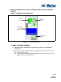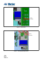
1
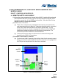
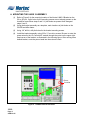
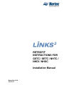
TM
RETROFIT
INSTRUCTIONS FOR
GSTC / SETC / NHTC /
NHDI / NHSC
Installation Manual
Manual No. H-504
2008-02-15
PROPRIETARY NOTICE
This document and the information disclosed herein are proprietary data of WALTER MEIER LTD.
Neither this document nor the information contained herein shall be reproduced used, or disclosed to
others without the written authorization of WALTER MEIER LTD., except to the extent required for
installation or maintenance of recipient’s equipment. All references to the NORTEC name should be
taken as referring to WALTER MEIER LTD.
LIABILITY NOTICE
NORTEC does not accept any liability for installations of humidity equipment installed by unqualified
personnel or the use of parts/components/equipment that are not authorized or approved by
NORTEC.
COPYRIGHT NOTICE
Copyright 2008, WALTER MEIER LTD. All rights reserved.
RECORD OF REVISIONS
For each revision, put the revised pages in your manual and discard the superseded pages. Write the
revision number and revision date, date put in manual, and the incorporator’s initials in the applicable
columns on the Record of Revisions.
Revision
Number
Page ii
2008-02-15
Revision
Date
Date Put
In Manual
By
Revision
Number
Revision
Date
Date Put
In Manual
By
TABLE OF CONTENTS
Subject
Page
10-00 LINKS 2 - FIELD INSTALLATION OF A SE-50
1.
A.
B.
FIELD INSTALLATION OF A SE-50 SERIES HUMIDIFIER WITH A LINKS 2 REMOTE PACKAGE . . . . . . . 2
INSTALLATION . . . . . . . . . . . . . . . . . . . . . . . . . . . . . . . . . . . . . . . . . . . . . . . . . . . . . . . . . . . . . . . . . . . . . 2
CONFIGURING THE HUMIDIFIERS . . . . . . . . . . . . . . . . . . . . . . . . . . . . . . . . . . . . . . . . . . . . . . . . . . . . 2
10-10 LINKS 2 - FIELD CONVERSION OF A GSTC/SETC
1.
A.
B.
C.
FIELD INSTALLATION OF A GSTC/SETC SERIES HUMIDIFIER WITH A LINKS 2 REMOTE PACKAGE . . 2
WIRING THE NORTEC LINKS 2 MODULE . . . . . . . . . . . . . . . . . . . . . . . . . . . . . . . . . . . . . . . . . . . . . . . 2
MOUNTING THE LINKS 2 ASSEMBLY . . . . . . . . . . . . . . . . . . . . . . . . . . . . . . . . . . . . . . . . . . . . . . . . . . 3
CONFIGURING THE HUMIDIFIERS . . . . . . . . . . . . . . . . . . . . . . . . . . . . . . . . . . . . . . . . . . . . . . . . . . . . 4
10-20 LINKS 2 - FIELD CONVERSION OF A NHTC
1.
A.
B.
FIELD INSTALLATION OF A NHTC SERIES HUMIDIFIER WITH A LINKS 2 REMOTE PACKAGE . . . . . . . 2
MOUNT THE LINKS 2 ASSEMBLY . . . . . . . . . . . . . . . . . . . . . . . . . . . . . . . . . . . . . . . . . . . . . . . . . . . . . 2
CONFIGURING THE HUMIDIFIERS . . . . . . . . . . . . . . . . . . . . . . . . . . . . . . . . . . . . . . . . . . . . . . . . . . . . 4
10-30 LINKS 2 - FIELD CONVERSION OF A NHDI/SC
1.
A.
B.
FIELD INSTALLATION OF A NHDI/SC SERIES HUMIDIFIER WITH A LINKS 2 REMOTE PACKAGE. . . . . 2
MOUNT THE LINKS 2 ASSEMBLY . . . . . . . . . . . . . . . . . . . . . . . . . . . . . . . . . . . . . . . . . . . . . . . . . . . . . 2
WIRING THE NORTEC LINKS 2 MODULE . . . . . . . . . . . . . . . . . . . . . . . . . . . . . . . . . . . . . . . . . . . . . . . 3
WARRANTY
LIST OF FIGURES
Figure
Page
10-10 LINKS 2 - FIELD CONVERSION OF A GSTC/SETC
Figure 1.
Figure 2.
Component Identification . . . . . . . . . . . . . . . . . . . . . . . . . . . . . . . . . . . . . . . . . . . . . . . . . . . . . . . . . . 2
LINKs2 Bracket Placement . . . . . . . . . . . . . . . . . . . . . . . . . . . . . . . . . . . . . . . . . . . . . . . . . . . . . . . . 3
10-20 LINKS 2 - FIELD CONVERSION OF A NHTC
Figure 1.
Figure 2.
Figure 3.
Component Identification . . . . . . . . . . . . . . . . . . . . . . . . . . . . . . . . . . . . . . . . . . . . . . . . . . . . . . . . . . 2
Hook Position . . . . . . . . . . . . . . . . . . . . . . . . . . . . . . . . . . . . . . . . . . . . . . . . . . . . . . . . . . . . . . . . . . . 3
Assembly Mounting Location . . . . . . . . . . . . . . . . . . . . . . . . . . . . . . . . . . . . . . . . . . . . . . . . . . . . . . . 3
10-30 LINKS 2 - FIELD CONVERSION OF A NHDI/SC
Figure 1.
Figure 2.
Figure 3.
Component Identification . . . . . . . . . . . . . . . . . . . . . . . . . . . . . . . . . . . . . . . . . . . . . . . . . . . . . . . . . . 2
LINKS 2 Bracket Placement. . . . . . . . . . . . . . . . . . . . . . . . . . . . . . . . . . . . . . . . . . . . . . . . . . . . . . . . 3
NHDI LINKS 2 Slave Installation . . . . . . . . . . . . . . . . . . . . . . . . . . . . . . . . . . . . . . . . . . . . . . . . . . . . 4
2008-02-15
10-00
LINKS 2 FIELD INSTALLATION
OF A SE-50
10-00
Page 1
2008-02-02
(1) FIELD INSTALLATION OF A SE-50 SERIES NORTEC LINKS 2 REMOTE
PACKAGE
A. STEP 1 - INSTALLATION
(1) Mount the LINKS 2 remote package in a convenient location. Note that the remote
package does not need to be mounted in close proximity to the humidifier.
(2) Connect power to the 24VAC and GND terminals of the LINKS 2 terminal strip. This
may be done in two ways:
(a)
A 120VAC to 24VAC plug-in transformer with screw terminals on the secondary
side has been supplied with this kit. Wire the transformer to the 24VAC and
GND terminals on the LINKS 2 terminal strip.
(b)
Connect power from the humidifier terminal strip (see wiring diagram for
details).
NOTE on 2(b)
Power to LINKS 2 module will be lost when the humidifier is switched off.
(3) Connect the slave humidifiers (if applicable) to the Nortec Links Module. A twisted
pair cable should be used so that the Net + terminal on the Links module should
connect to the first pin (bottom-most pin) of the TB3 connector. The Net – terminal on
the module should be connected to the second pin of the TB3 connector. Refer to
the unit’s wiring diagram for more information.
A. STEP 2 – CONFIGURING THE HUMIDIFIERS
NOTE
If the LINKS 2 remote package was shipped with the humidifiers, this step will have
already been performed by the factory.
(1) Since Nortec LINKS 2 can connect to a maximum of 8 units, it will be necessary to
set the unit address for each humidifier. The lead unit can be determined by the
presence of the LINKS 2 module. The slave humidifiers can be given a unit address
according to the number the unit will have on the networked chain.
(2) To set the network address access the User Parameter level in the humidifier
software menu. Scroll down to Modbus Settings and press enter.
(3) In order to change the current modbus address, press the up and down arrows on
the keypad at the same time. When prompted, enter the code 0335.
(4) Once the password is set select the modbus address heading and press enter. Use
the up and down arrows to change the address setting.
(5) Determine the desired humidifier ordering on the network. To change the network
instance follow step 3 and enter the parameter value of 2 for unit 2, 3 for unit 3 and
soon.
10-00
Page 2
2008-02-02
10-10
LINKS 2 FIELD CONVERSION OF
A GSTC/SETC
10-10
Page 1
2008-02-15
(1) FIELD CONVERSION OF A GSTC/SETC SERIES HUMIDIFIER WITH
NORTEC LINKS 2
BACNET, LONWORKS AND N2 MODULES:
A. WIRING THE NORTEC LINKS 2 MODULE
(1) Most of the wiring connections for the new Nortec LINKS 2 module will have already
been finished at the factory, however, there are a few connections that will need to
be made to connect the unit the GS/SE series humidifier. Refer the LINKs 2 wiring
diagram included in the package for details.
(2) Module Power Connections:
(a)
There will be a wire harness provided that will consist of a red and blue wire,
each terminated with a ring terminal. These wires should already be connected
to the 24VAC and GND terminals on the LINKS 2 terminal strip. The ring
terminal of the red wire is to be connected to the 24V side of the 120/24 VAC
transformer located at the bottom, left of the electrical compartment. The
connection point will be labelled XF at the transformer.
(b)
The ring terminal of the blue wire will need to be connected to the ground
terminal on the 120/24 VAC transformer.
(3) Humidifier Communication Connection:
(a)
On the Nortec LINKS 2 assembly there will be a black 2-pole connector present
that is connected to a white and black wire. This connector is to be plugged into
the TB3 jack on the right side of the humidifier mainboard.
LAN
Router or
Switch
LINKS 2
Module
Router
Power
Supply
OnLine
Module
Figure 1. Component Identification
10-10
Page 2
2008-02-15
B. MOUNTING THE LINKS 2 ASSEMBLY
(1)
Refer to Figure 2 for the mounting location of the Nortec LINKS 2 Bracket on the
GS or SE unit. If pilot holes for the mounting screws are not already present on the
humidifier frame follow steps 2 and 3. If pilot holes are present then disregard
steps 2 and 3.
(2)
Using the bracket assembly as a template, mark locations of pilot holes on the
GS/SE humidifier frame.
(3)
Using 1/8” drill bit, drill pilot holes for the bracket mounting screws.
(4)
Install the bracket assembly using 8-32x ½” hex-drive screws. Be sure to route the
power wires for the I/O Controller-E module through the cutout on the upper righthand corner of the bracket, as illustrated in the following figure. After running wires
behind bracket, route the power leads into the main wire track.
Screw
Location
Figure 2. LINKS 2 Bracket Placement
10-10
Page 3
2008-02-15
C. CONFIGURING THE HUMIDIFIERS
(1)
Since Nortec LINKS 2 can connect to a maximum of 8 units, it will be necessary to
set the unit address for each humidifier. The lead unit can be determined by the
presence of the Links module. The slave humidifiers can be given a unit address
according to the number the unit will have on the networked chain.
(2)
To set the network address access the User Parameter level in the humidifier
software menu. Scroll down to Modbus Settings and press enter.
(3)
In order to change the current Modbus address, press the up and down arrows on
the keypad at the same time. When prompted, enter the code 0335.
(4)
Once the password is set select the Modbus address heading and press enter.
Use the up and down arrows to change the address setting.
(5)
Determine the desired humidifier ordering on the network. To change the network
instance follow step 3 and enter the parameter value of 2 for unit 2, 3 for unit 3 and
so on.
(6)
Place the appropriate Unit Identifier label on each humidifier. These labels should
be placed on the unit where the electrical control punch-outs are located at the top
of the humidifier.
(7)
Connect the slave humidifiers (if applicable) to the Nortec Links Module. A twisted
pair cable should be used so that the Net + terminal on the Links module should
connect to the first pin (bottom-most pin) of the TB3 connector. The Net – terminal
on the module should be connected to the second pin of the TB3 connector. Refer
to the unit’s wiring diagram for more information.
10-10
Page 4
2008-02-15
10-20
LINKS 2 FIELD CONVERSION OF
A NHTC
10-20
Page 1
2008-02-15
(1) FIELD CONVERSION OF A NHTC SERIES HUMIDIFIER WITH NORTEC
LINKS 2
BACNET, LONWORKS AND N2 MODULES:
OnLine
Module
LINKS 2
Module
LAN Router
or Switch
(BACnet/IP)
Router Power
Supply
Figure 1. Component Identification
A. MOUNT THE LINKS 2 ASSEMBLY
(1) The Nortec LINKS 2 assembly mounts on the top, right corner of the electrical
compartment.
(2) Ensure that the rear, upwards facing hook engages the proper cooling louver at the
back of the humidifier cabinet.
(a)
Fasten the bracket assembly to the humidifier ‘top’ using the 3 8-32 X ½” selftapping screws provided with the kit.
10-20
Page 2
2008-02-15
Hook
Position
Figure 2. Hook Position
Hook
Position
Figure 3. Assembly Mounting Location
10-20
Page 3
2008-02-15
B. CONFIGURING THE HUMIDIFIERS
(1)
Since Nortec LINKS 2 can connect to a maximum of 8 units, it will be necessary to
set the unit address for each humidifier. The lead unit can be determined by the
presence of the Links module. The slave humidifiers can be given a unit address
according to the number the unit will have on the networked chain.
(2)
Press the menu button and enter the password 0459.
(3)
Scroll down and select Factory Settings.
(4)
Scroll and select Core Parameters.
(5)
Select Modbus Parameters.
(6)
Set the communication parity to Even.
(7)
Set the appropriate Modbus address according to the unit ordering.
(8)
Connect the slave humidifiers (if applicable) to the Nortec Links Module. A twisted
pair cable should be used so that the Net + terminal on the Links module should
connect to the Net + terminal on the slave unit (NHTC). The Net – terminal on the
module should be connected to the Net – terminal on the slave unit. Refer to the
unit’s wiring diagram for more information.
10-20
Page 4
2008-02-15
10-30
LINKS 2 FIELD CONVERSION OF
A NHDI/SC
10-30
Page 1
2008-02-15
(1) FIELD CONVERSION OF A NHDI/SC SERIES HUMIDIFIER WITH NORTEC
LINKS 2
BACNET, LONWORKS AND N2 MODULES:
LINKS 2
Module
Router Power
Supply
OnLine
Module
LAN Router
or Switch
(BACnet/IP)
Figure 1. Component Identification
A. MOUNT THE LINKS 2 ASSEMBLY
(1) Refer to Figure 2 for the mounting location of the Nortec LINKS 2 Bracket on the
NHDI or NHSC unit. If pilot holes for the mounting screws are not already present on
the humidifier frame follow steps 2 and 3. If pilot holes are present then disregard
steps 2 and 3.
(2) Using the bracket assembly as a template, mark locations of pilot holes on the
NHDI/SC humidifier cabinetry.
(3) Using 1/8” drill bit, drill pilot holes for the bracket mounting screws.
(4) Install the bracket assembly using the provided #8-32 screws. Note that 2 #8-32 nuts
have been supplied to secure the 2 top mounts. The third screw will thread into the
humidifier cabinet itself.
10-30
Page 2
2008-02-15
Use 8-32
screws
with nuts
Use 8-32
screw
only.
Figure 2. LINKS 2 Bracket Placement
B. WIRING THE NORTEC LINKS 2 MODULE
(1)
Most of the wiring connections for the Nortec LINKS 2 module will have already
been finished at the factory, however, there are a few connections that will need to
be made to connect the module to the NHDI/SC series humidifier. Refer the LINKS
2 wiring diagram included in the package for details.
(2)
Module Wire Connections:
10-30
Page 3
2008-02-15
(a)
There will be a wire harness provided that will consist of a red and blue wire,
each terminated with a bare end. These wires should already be connected
to the 24VAC and GND terminals on the LINKS 2 terminal strip. Both wires
will be connected to the 5-pole connector labelled X1 (Main Supply) located
on the humidifier support board. The red wire is to be connected to the
terminal labelled L1. The blue wire is to be connected to the terminal labelled
N.
(b)
A loose ribbon cable with a 10-pin header plug and a 20-pin header plug will
be included with the kit. The 20-pin header plug should be connected to the
J2 connector on the TTL-to-RS485 converter located on the back of the
LINKS 2 mounting bracket. The 10-pin header plug should be connected to
the COM PORT connector located on the NHDI/SC Logic Board.
Figure 3. NHDI LINKS 2 Slave Installation
(3)
Installation of LINKS 2 Slave Option
(a)
The LINKS 2 module is capable of supporting up to 8 humidifiers when each
unit is equipped with a TTL to RS-485 signal converter. The LINKS 2 slave
option consists of a small bracket with the signal converter mounted on one
side. In addition a terminal strip is provided to allow the humidifiers to be
wired back to the master module.
(b)
Mount the LINKS slave option on any humidifier that will be connected to the
master module. The slave option mounts in the same location as the master
LINKS module. Use 2 #8-32 screws and 2 #8-32 nuts to secure the bracket to
the top of the humidifier cabinet.
(c)
The provided 3-position terminal strip will be installed next to the standard
humidifier strip using 2 #6-32 screws. For units being retrofitted, the existing
terminal strip may have to be shifted to the right for the LINKS terminal strip
to fit.
(d)
Connect the 4-pin modular plug into one of the 2 modular jacks on the TTL to
RS-485 signal converter.
10-30
Page 4
2008-02-15
(4)
10-30
Page 5
2008-02-15
Configuring the Humidifiers
(a)
Since Nortec LINKS 2 can connect to a maximum of 8 units, it will be
necessary to set the unit address for each humidifier. The lead unit can be
determined by the presence of the LINKS module and should be set to
modbus address 1. The slave humidifiers can be given a unit address
according to the number the unit will have on the networked chain.
(b)
In order to change the current modbus address, press the up and down
arrows on the keypad at the same time. When prompted, enter the code
8808. Note: Each column of the password may be adjusted with the up or
down arrow keys. Once that number is set, pressing the enter key will move
the cursor to the next column.
(c)
Once the password is set, select the modbus address heading and press
enter. Use the up and down arrows to change the address setting.
(d)
Determine the desired humidifier ordering on the network. To change the
network instance follow step 3 and enter the parameter value of 2 for unit 2, 3
for unit 3 and so on.
(e)
Place the appropriate Unit Identifier label on each humidifier. These labels
should be placed below the user terminal strip located in the electrical cabinet
section of the humidifier.
(f)
Connect the slave humidifiers (if applicable) to the Nortec LINKS 2 Module. A
twisted pair cable should be used so that the Net + terminal on the LINKS
module connects to the Net+ terminal of the NHDI/SC slave option. The Net –
terminal on the LINKS 2 module should also be connected to the Netterminal of the slave option. Refer to the unit’s wiring diagram for more
information.
WARRANTY
(1) WALTER MEIER INC. and/or WALTER MEIER LTD. (hereinafter collectively referred
to as THE COMPANY), warrant for a period of two years after installation or 30 months
from manufacturer’s ship date, whichever date is earlier, that THE COMPANY’s
manufactured and assembled products, not otherwise expressly warranted (with the
exception of the cylinder), are free from defects in material and workmanship. No
warranty is made against corrosion, deterioration, or suitability of substituted materials
used as a result of compliance with government regulations.
(2) THE COMPANY’s obligations and liabilities under this warranty are limited to furnishing
replacement parts to the customer, F.O.B. THE COMPANY’s factory, providing the
defective part(s) is returned freight prepaid by the customer. Parts used for repairs are
warranted for the balance of the term of the warranty on the original humidifier or
90 days, whichever is longer.
(3) The warranties set forth herein are in lieu of all other warranties expressed or implied
by law. No liability whatsoever shall be attached to THE COMPANY until said products
have been paid for in full and then said liability shall be limited to the original purchase
price for the product. Any further warranty must be in writing, signed by an officer of
THE COMPANY.
(4) THE COMPANY’s limited warranty on accessories, not of the companies manufacture,
such as controls, humidistats, pumps, etc. is limited to the warranty of the original
equipment manufacturer from date of original shipment of humidifier.
(5) THE COMPANY makes no warranty and assumes no liability unless the equipment is
installed in strict accordance with a copy of the catalog and installation manual in effect
at the date of purchase and by a contractor approved by THE COMPANY to install
such equipment.
(6) THE COMPANY makes no warranty and assumes no liability whatsoever for
consequential damage or damage resulting directly from misapplication, incorrect
sizing or lack of proper maintenance of the equipment.
(7) THE COMPANY retains the right to change the design, specification and performance
criteria of its products without notice or obligation.
INSTALLATION DATE (MM/DD/YYYY)
MODEL #
SERIAL #
CYLINDER #
Authorized Agent:
U.S.A.
Walter Meier (Climate USA) Inc.
826 Proctor Avenue
Ogdensburg, NY 13669
TEL: 1-866-NORTEC-1
EMAIL: [email protected]
WEBSITE: www.humidity.com
CANADA
Walter Meier (Climate Canada) Ltd.
2740 Fenton Road
Ottawa, ON K1T 3T7
TEL: 1-866-NORTEC-1
FAX: (613) 822-7964