1
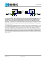
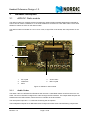
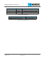
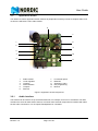
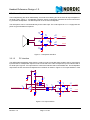
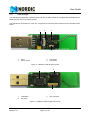
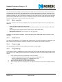
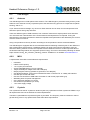
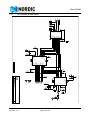
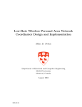
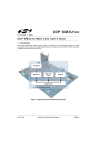
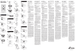
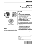
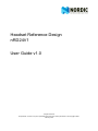
Headset Reference Design
nRD24V1
User Guide v1.0
All rights reserved.
Reproduction in whole or in part is prohibited without the prior written permission of the copyright holder.
February 2007
User Guide
Liability disclaimer
Nordic Semiconductor ASA reserves the right to make changes without further notice to the product to
improve reliability, function or design. Nordic Semiconductor ASA does not assume any liability arising out
of the application or use of any product or circuits described herein.
Life support applications disclaimer
These products are not designed for use in life support appliances, devices, or systems where malfunction
of these products can reasonably be expected to result in personal injury. Nordic Semiconductor ASA customers using or selling these products for use in such applications do so at their own risk and agree to fully
indemnify Nordic Semiconductor ASA for any damages resulting from such improper use or sale.
Contact details
For your nearest dealer, please see http://www.nordicsemi.no
Receive available updates automatically by subscribing to eNews from our homepage or check our website regularly for any available updates.
Main office:
Otto Nielsen’s vei 12
7004 Trondheim
Phone: +47 72 89 89 00
Fax: +47 72 89 89 89
www.nordicsemi.no
Revision History
Date
February 2007
Revision 1.0
Version
1.0
Page 2 of 25
Description
Headset Reference Design v1.0
Contents
1
2
3
3.1
3.1.1
3.1.2
3.1.3
3.1.4
3.1.5
3.1.6
3.1.7
3.2
3.2.1
3.2.2
3.2.3
3.2.4
3.2.5
3.2.6
3.3
3.3.1
3.3.2
3.3.3
3.3.4
3.3.5
3.3.6
4
4.1
4.1.1
4.1.2
4.1.3
4.1.4
4.1.5
4.2
4.2.1
4.2.2
4.2.3
5
5.1
5.2
5.3
5.4
Introduction ................................................................................................. 4
System Description ..................................................................................... 5
Hardware description .................................................................................. 7
nRD24V1 Radio module ...................................................................... 7
Audio Codec..................................................................................... 7
Micro controller................................................................................. 8
Radio circuit ..................................................................................... 8
Antenna matching network............................................................... 8
Power supply.................................................................................... 8
Programming.................................................................................... 8
Specifications ................................................................................... 9
Application board ................................................................................. 10
Audio interface ................................................................................. 10
Jumpers ........................................................................................... 12
Antenna............................................................................................ 12
Power supply.................................................................................... 12
Buttons ............................................................................................. 13
Programming.................................................................................... 13
USB dongle .......................................................................................... 14
USB Interface................................................................................... 15
Micro controller................................................................................. 15
Radio circuit ..................................................................................... 15
Power supply.................................................................................... 15
Programming.................................................................................... 15
Specifications ................................................................................... 16
Hardware design guidelines........................................................................ 17
Headset ................................................................................................ 17
Antenna............................................................................................ 17
Interfaces ......................................................................................... 17
Crystals ............................................................................................ 18
MCU ................................................................................................. 18
Battery.............................................................................................. 18
USB dongle .......................................................................................... 19
Antenna............................................................................................ 19
MCU ................................................................................................. 19
Crystals ............................................................................................ 19
Appendix ..................................................................................................... 20
Bill Of Materials (BOM) ........................................................................ 20
Application board schematics .............................................................. 23
RF module schematics......................................................................... 24
USB dongle schematics ....................................................................... 25
Revision 1.0
Page 3 of 25
User Guide
1
Introduction
This user guide is for the nRD24V1 headset reference design, a voice quality wireless headset for Voice
over IP (VoIP) applications. The quality of the audio in this design is the same as the audio quality in telephony.
This user guide describes the nRD24V1 system, HW modules and gives guidelines on how to take this reference design and build it into a headset application for a finished product.
The nRD24V1 consists of a USB dongle and two application boards with a radio module mounted. You can
establish a full duplex voice link between one application board and the USB dongle or between the two
application boards.
Target applications for the nRD24V1 are:
•
•
•
Voice over IP headsets
Short range intercom applications
Toys
Revision 1.0
Page 4 of 25
Headset Reference Design v1.0
2
System Description
The headset unit can be used to communicate with either a USB dongle or an audio dongle.
Note: The audio dongle is simply a headset unit with different firmware and jumper settings.
Figure 1. ”Headset unit with a USB configuration” and Figure 2. ”System diagram of headset unit with USB
configuration” illustrate the headset unit with a USB configuration.
Headset
unit
USB
dongle
Figure 1. Headset unit with a USB configuration
Application
Voice
Protocol
Application
ShockBurst
MCU
I/O
I/O
Audio
Out
Audio
In
PHY
RF
ShockBurst
PHY
RF
Voice
Protocol
USB
Audio Controller
MCU
I/O
I/O
I/O
DAC
USB
USB
In/Out
ADC
Buttons
LED
LED
Figure 2. System diagram of headset unit with USB configuration
Figure 3. ”Headset unit with an audio dongle configuration” and Figure 4. ”System diagram of headset unit
with audio dongle configuration” illustrate the headset unit with audio dongle configuration.
Headset
unit
Audio
dongle
Figure 3. Headset unit with an audio dongle configuration
Revision 1.0
Page 5 of 25
User Guide
Application
Voice
Protocol
Application
ShockBurst
MCU
I/O
I/O
Audio
Out
Audio
In
PHY
RF
ShockBurst
PHY
RF
Voice
Protocol
MCU
I/O
I/O
DAC
DAC
ADC
ADC
Buttons
LED
LED
Audio
Out
Audio
In
Buttons
Figure 4. System diagram of headset unit with audio dongle configuration
The headset unit and the audio dongle are based on the same hardware. Both use an audio codec to provide coding and decoding of the analog audio signals to 16-bit linear PCM code. This bit stream is processed by the micro controller to an 8-bit a-law bit stream, which is sent to the nRF24L01 for wireless
transmission. The nRF24L01 uses the ShockBurst feature to transmit and receive the RF packets in a time
multiplexed scheme. The micro controller fetches received 8-bit a-law samples from the nRF24L01, converts to 16-bit linear PCM, and outputs to the audio codec. Button status is read by the MCU and embedded in the RF packets.
The USB Dongle uses a USB Audio Controller to handle the USB interface. The audio samples are 16 bit
linear PCM between the USB Audio Controller and the micro controller, where the micro controller acts as
a bus master. The audio frame signals are derived from clock output from the USB Audio Controller to
keep the audio frames in sync with the USB audio frames. The micro controller can also access the USB
HID interface through the I2C bus, also with the micro controller as the bus master. The USB HID interface
is used to upstream button status received from the headset to the USB host. The micro controller converts
the 16 bit linear PCM code to an 8-bit a-law bit stream, which is sent to the nRF24L01 for wireless transmission. The nRF24L01 uses the ShockBurst feature to transmit and receive the RF packets in a time multiplexed scheme.
Revision 1.0
Page 6 of 25
Headset Reference Design v1.0
3
Hardware description
3.1
nRD24V1 Radio module
The radio module is a complete system for telephone quality wireless headset applications intended for
VoIP. It can be used in a headset, or in an audio module for connection to a PC audio outlet. There are 6
GPIOs for buttons or LEDs on the radio module.
The radio module is mounted on a 25 x 12 x 0.8 mm, 4-layer FR4 circuit board, with components on one
side.
5
1
4
2
3
1
2
3
RF crystal
nRF24L01
MCU
4
5
Audio codec
MCU crystal
Figure 5. nRD24V1 radio module
3.1.1
Audio Codec
The audio codec is a XE3005 from Semtech that receives a 4.096 MHz master clock from the micro controller. The micro controller configures the codec through the SPI interface. The 8 ksps audio samples are
transferred on the I2S interface, where the micro controller is the bus master.
The microphone input has a 1.1 VDC bias for driving the microphone.
The loudspeaker outputs are a differential class D output and need some external filtering components.
Revision 1.0
Page 7 of 25
User Guide
3.1.2
Micro controller
The micro controller is an AVR, ATmega88 and runs on a 4.096 MHz crystal. The micro controller’s main
tasks are:
•
•
•
•
Setting up codec and RF circuits.
Converting 16 bit PCB audio samples from the codec to 8 bit a-law samples to the radio circuit.
Converting 8-bit a-law samples from the radio circuit to 16-bit linear PCM.
Handling the RF protocol.
Additionally, five button inputs are scanned and one output is provided for driving. For example, this can be
used for an LED.
3.1.3
Radio circuit
The radio circuit (nRF24L01) is a complete radio transceiver for use in the unlicensed 2.4 GHz band. A 16
MHz crystal is used as a frequency reference for the RF. The RF output is matched to approximately 50
ohm at the antenna port. See section 3.1.4 ”Antenna matching network” below.
3.1.4
Antenna matching network
The RF output of the radio module is matched to approximately 50 ohm. An antenna is needed to set up
the RF link. There is a variety of different antenna types, please see section 4.1.1 ”Antenna” for more information.
3.1.5
Power supply
The module needs a power supply in the range of 1.9 to 3.3 Volts. The module has been tested with a supply consisting of two ZinkAir cells (type 675) in series. Check the current consumption values shown in
Table 1. ”Electrical Specifications” below.
Note: Not all battery types are capable of handling the peak and average currents, even if the battery capacity is sufficient.
3.1.6
Programming
The module can be programmed using the ISP connector on the application board (see section 3.2 ”Application board”), by connecting the appropriate pins on the module, or by using test probes on the corresponding exposed vias on the back of the board.
Revision 1.0
Page 8 of 25
Headset Reference Design v1.0
3.1.7
Specifications
Operating conditions
Supply voltage
Current consumption
Status
Idle
Connected
Radio frequency
Output power
Value
1.9 - 3.6 V
< 1 mA average (15 mA peak) at 2.5 V supply
< 7 mA average (15 mA peak) at 2.5 V supply
2402-2478 MHz
0 dBm
Table 1. Electrical Specifications
PCB attributes
PCB type
PCB dimension (length x width x height)
Description
0.8 mm 4 layer FR4
25 mm x 12 mm x 0.8 mm
Table 2. Physical Specifications
Revision 1.0
Page 9 of 25
User Guide
3.2
Application board
The nRF24L01-VHR1 application board contains all peripherals necessary to build a complete audio module from the nRF24L01-VHR1 radio module.
6
7
1
8
2
9
3
4
10
5
11
1
2
3
4
5
6
Radio module
Linear regulator
Jumpers
Audio interface
Jumpers
Switch 6
7
8
9
10
11
P3 external power
Batteries
Switches 7 and 8
ISP programming
Buttons
Figure 6. Application board components
3.2.1
Audio interface
This module can be used to set up a wireless audio link, for example, from a PC to a headset. The radio
module is the same for both sides of the link, but needs some external components to interface with either
the PC audio connections, or a microphone/loudspeaker for a headset.
Revision 1.0
Page 10 of 25
Headset Reference Design v1.0
3.2.1.1
Headset interface
The loudspeaker(s) are driven differentially, and need some filtering due to the class D output amplifier of
the audio codec. Figure 7. ”Loudspeaker interface” shows a typical filter network that can be used for driving a headset loudspeaker. The filter depends on the chosen loudspeaker.
The microphone can be connected directly to the codec input. The codec input has a 1.1 V supply that can
power a typical headset microphone.
100p
C1
R1
56
L1
470u
AOUTP
C2
4.7u
C3
4.7u
L2
470u
AOUTN
56
R2
C4
100p
Figure 7. Loudspeaker interface
3.2.1.2
PC interface
The differential loudspeaker output from the codec must be connected single ended to the PC microphone
input and the PC loudspeaker output must be connected to the codec microphone input to interface with a
PC audio port. Figure 8. ”PC input interface” shows the networks that accommodate this. The loudspeaker
output from the PC must be level adjusted and a network as shown in Figure 9. ”PC output interface” used.
R3
1k
C5
10n
C6
10u
R4
22k
U1
PC microphone input
C7
100n
V+
1
5
+
LM7301
R5
22k
R6
22k
4
100p
C1
R7
4.7k
V-
4.7k
R8
2
C3
4.7u
2.2u
C9
Figure 8. PC input interface
L2
470u
AOUTN
C4
100p
Page 11 of 25
L1
470u
AOUTP
C2
4.7u
3
R9
22k
Revision 1.0
R1
56
C8
2.2u
56
R2
User Guide
C1
R1
C2
PC loudspeaker out
AIN
2.2u
1k
2.2u
R2
47
Figure 9. PC output interface
3.2.2
Jumpers
The application board can be set up to interface a headset microphone and loudspeaker, or a PC audio
outlet by placing the jumpers as shown in Table 3. ”Audio filter settings” below. The filter components
mounted should be appropriate for most headset loudspeakers.
CJ2
Connecting to
Connect to headset
headset
microphone.
Connecting to PC Connect to PC microphone input
CJ3
Connect to headset
loudspeaker
Connect to PC loudspeaker output
W1
W2
Mount jumpers 4 Mount jumper 2.
and 5
Mount jumpers 1, Mount jumper 1.
2 and 3
Table 3. Audio filter settings
3.2.3
Antenna
The RF output of the radio module is matched to approximately 50 ohm. An antenna must be connected to
the SMA connector to set up an RF link.
3.2.4
Power supply
The application board is fitted with two coin-cell battery holders, connected in series, for use with ZinkAir
(type 675) batteries. The board also contains a footprint for a CR2 Li battery holder (1/2 AA, Bulgin
BX0031). Alternatively, an external power supply can be connected to P3. You select battery or external
voltage with SW6.
The voltage supply to the RF module should be between 1.9 and 3.6 V. If the onboard 2.5 V linear regulator is used, the input voltage should be between 3 and 15 V. The linear regulator can be switched on or
bypassed with SW7 and SW8 (both switches should have the same position).
Note: Do not exceed 3.6 V when using external voltage unless the linear regulator is used, as this
can damage the radio module.
Revision 1.0
Page 12 of 25
Headset Reference Design v1.0
3.2.5
Buttons
There are five buttons on the application board and these are connected to the AVR micro controller on the
radio module as shown in Figure 10. ”Button mapping”.
SW1
AVR pin 23
SW2
AVR pin 24
SW3
AVR pin 25
SW4
AVR pin 26
SW2
AVR pin 27
Figure 10. Button mapping
3.2.6
Programming
The radio module can be programmed through the 6-pin ISP connector (P1) with an AVR programming
tool like the STK500 from Atmel. The programming procedure is as follows:
1.
2.
3.
If the unit has never been programmed, set the AVR fuses:
• Preserve EEPROM memory through chip erase cycle; [EESAVE = 0]
• Brown-out detection level at Vcc=1.8V; [BODLEVEL=110]
• Clock output on PORTB0; [CKOUT=0]
• Ext.Crystal Osc. Frequency 3.0 - 8.0MHz; [CKSEL=1101 SUT=11]
Write the SW hex file into the AVR program memory.
Write a 3-byte ID into the AVR EEprom. The address should be written with the MSB at address
00.
Revision 1.0
Page 13 of 25
User Guide
3.3
USB dongle
The USB dongle establishes a wireless audio link with the radio module in a headset and is identified as an
audio device in the PC operating system.
The USB dongle is mounted on a 0.8 mm, 4-layer FR4 circuit board, with components on both sides of the
board.
1
3
2
4
1
2
MCU
MCU crystal
3
4
nRF24L01
RF crystal
Figure 11. nRD24V1 USB dongle top side
2
1
3
1
2
USB MCU
EE Prom
3
ISP connector
Figure 12. nRD24V1 USB dongle bottom side
Revision 1.0
Page 14 of 25
Headset Reference Design v1.0
3.3.1
USB Interface
The USB interface is handled by the Sonix SN11220 USB Audio Controller. All the USB communications
are handled by the SN11220. The audio samples are 16 bit linear PCM on the I2S port, where the micro
controller acts as a bus master (PADFUN mode 4’1100 in the SN11220ACF data sheet). The audio frame
signals are derived from the 2.048 MHz clock output from the USB controller. This synchronizes the audio
frames with the USB audio frames. The micro controller can also access the USB HID interface through
the I2C bus, also with the micro controller as the bus master.
3.3.2
Micro controller
The micro controller is an AVR, ATmega88 that runs on a 6.00 MHz crystal. The micro controller’s main
tasks are:
•
•
•
•
•
Setting up USB controller and radio circuits.
Converting 16 bit PCM audio samples from the USB controller to 8 bit a-law samples for the radio
circuit.
Converting 8-bit a-law samples from the radio circuit to 16-bit linear PCM.
Handling the RF protocol.
Optional HID interface for communication with PC application.
In addition, an LED output is available. The LED will light up when USB audio activity is present on the
USB port.
3.3.3
Radio circuit
The radio circuit (nRF24L01) is a complete radio transceiver for use in the unlicensed 2.4 GHz band. A 16
MHz crystal is used as frequency reference for the RF and an antenna is included in the layout.
3.3.4
Power supply
The USB dongle is powered from the USB port and needs no extra supply.
3.3.5
Programming
A 6-pin ISP connector is available on the back of the PCB. The included ISP cable can be used to connect
this connector to an AVR programming tool like the STK500 from Atmel.The programming procedure is as
follows:
1.
2.
3.
If the unit has never been programmed, set the AVR fuses:
• Preserve EEPROM memory through chip erase cycle; [EESAVE = 0]
• Brown-out detection level at Vcc=2.7V; [BODLEVEL=101]
• Ext. Full-swing Crystal; [CKSEL=0111 SUT=01]
Write the SW hex file into the AVR program memory.
Write a 3-byte ID into the AVR EEprom. The address should be written with the MSB at address
00.
Revision 1.0
Page 15 of 25
User Guide
3.3.6
Specifications
Operating conditions
Supply voltage
Current consumption
Status
Idle
Connected
Radio frequency
Output power
Value
4.5 - 5.5 V
< 24 mA
< 28 mA
2402-2478 MHz
0 dBm
Table 4. Electrical Specifications
PCB attributes
PCB type
PCB dimension (length x width x height)
Description
0.8mm 4 layer FR4
42mm x 16mm x 0.8mm
Table 5. Physical Specifications
Revision 1.0
Page 16 of 25
Headset Reference Design v1.0
4
Hardware design guidelines
This chapter describes important issues that might affect you when developing the headset reference
design for a finished product. The USB dongle can be used as-is, but the headset must be redesigned to fit
into a headset for a finished product. However, the radio module mounted on the headset can be used asis together with the audio interfaces from the application board.
Note: Most radio regulations do not allow more than 0dBm output power without doing proper frequency hopping. Adding a PA to this design requires a major re-design of the radio protocol
because the headset reference design uses a frequency agility protocol.
4.1
Headset
The radio module is used as-is in the headset design, but it must be interfaced in a way that ensures optimal performance.
4.1.1
Antenna
The radio module is connected to the antenna on the application board. This antenna does not fit into a
headset design for a finished product, so using the radio module in a headset application for a finished
product will require a different type of antenna.
In a headset application for a finished product, the radio module must be mounted on a PCB with an
antenna terminal. On this antenna terminal, any 50 ohm 2.4GHz antenna can be used, from an inexpensive PCB antenna to space saving chip antennas.
There are different types of PCB antennas, from inverted F antennas to simple quarter wave antennas.
You must know the characteristics of the chosen antenna and implement it as required. Tuning the
antenna will be necessary because an antennas impedance and performance is affected by the environment the antenna is used in.
Using a chip antenna must only be done according to the chip antenna vendors recommendations.
The radio module is equipped with the recommended antenna matching network layout for the nRF24L01.
When operating from the application board, the radio module’s antenna matching network is tuned to
match the application board antenna impedance.
When using the radio module in a headset application for a finished product it is important to tune the
antenna matching network to match the impedance at the antenna’s terminal. Another important task of
the antenna matching network is to suppress spurious energy. You can achieve this by following our white
paper called “Tuning_the_nFR24xx_matching_network” available on our website www.nordicsemi.no.
4.1.2
Interfaces
4.1.2.1
Buttons
Any active closed push buttons referring to ground can be used because the MCU used on the radio module has internal pull-up resistors on the button input signals. The radio module can handle up to five buttons.
Revision 1.0
Page 17 of 25
User Guide
4.1.2.2
Audio interface
The audio interfaces from the application board should be used when using the radio module as-is in a
design. The audio interfaces are matched to the used audio codec on the radio module. Using a different
codec or load on the interfaces requires redesign of the audio interfaces.
4.1.3
Crystals
The crystal used as the RF crystal is a 16 MHz crystal. Any replacement of this crystal must fulfill the crystal requirements found in the nRF24L01 Product Specification.
The MCU crystal fulfills the requirements given by the MCU. The frequency must be 4.096MHz in order to
get the timing correct. Any replacements must follow these requirements.
4.1.4
MCU
It is important that the MCU has a double buffered SPI in both the TX and RX direction because the MCU
handles the audio stream and requires it to be continuous.
A replacement of the MCU must fulfill these requirements:
•
•
•
•
•
•
•
•
•
•
•
•
4.1.5
8-bit MCU
4.096 MHz clock frequency
1 to 2 cycles per instruction
4bytes E2PROM Memory (can be external)
1kbyte of IRAM (can maybe work with 512kbytes)
8kbyte program memory (possible to get down to 5 to 6kbytes)
One Double buffered, synchronous hardware SPI both on RX and TX -or- Ideally I2S interface
One SPI port for RF and codec
Watchdog times for power management
One 16-bit timer (Master sync clock)
One 8-bit timer (hardware sync clock)
1.9 to 3.6V supply voltage
Battery
The batteries included in the reference design kit are of the type Zink-Air (Zn), size 675. Two batteries of
this size are connected in series to achieve the supply voltage needed.
Any battery that can supply a voltage between 1.9V and 3.6V and sustain the peak current of 15mA can be
used in this application.
You can calculate the battery lifetime in both “talk time” and “standby time” from the average current consumption. At Vdd=3V the average current consumption in connect mode is 7mA and the average current
consumption in idle mode is 250µA. (At Vdd=2V they are 5.7V and 230µA, respectively.) A battery with
capacity 630mAh, like the Zn 675, will have the following battery lifetime:
•
•
Talk time: 630mAh/7mA = 90h.
Standby time: 630mAh/250µA=2520h.
The figures for Vdd=3V are used because the two batteries in series have a nominal output voltage of
2.8V.
Revision 1.0
Page 18 of 25
Headset Reference Design v1.0
4.2
USB dongle
4.2.1
Antenna
The USB Dongle uses a PCB quarter wave antenna. The USB Dongle is production ready, and any modifications to the antenna are only required as part of the antenna tuning process to compensate for plastic
housing, and so on.
If you want an antenna redesign, any 50 ohm 2.4GHz antenna can be used, from an inexpensive PCB
antenna to space saving chip antennas.
There are different types of PCB antennas, from inverted F antennas to simple quarter wave antennas.
You must know the characteristics of the chosen antenna and implement it as required. Tuning the
antenna will be necessary because an antenna’s impedance and performance are affected by the environment the antenna is used in.
Using a chip antenna must only be done according to the chip antenna vendors recommendations.
The USB Dongle is equipped with the recommended antenna matching network layout for the nRF24L01
and a PCB quarter wave antenna. If a different antenna is going to be used it is important to tune the
antenna matching network to match the impedance at the antenna’s terminal. Another important task of
the antenna matching network is to suppress spurious energy. This can be achieved by following our White
Paper named “Tuning_the_nFR24xx_matching_network” available on our website www.nordicsemi.no
4.2.2
MCU
A replacement of the MCU must fulfill these requirements:
•
•
•
•
•
•
•
•
•
•
•
•
•
4.2.3
8-bit MCU
6 MHz clock frequency
1 to 2 cycles per instruction
4bytes E2PROM Memory (can be external)
1kbyte of IRAM (can maybe work with 512kbytes)
8kbyte program memory (possible to get down to 5 to 6kbytes)
One Double buffered, synchronous hardware SPI both on RX and TX -or- Ideally I2S interface
One SPI port for RF and codec
One two wire interface to USB Audio Controller for call control (open drain type)
Watchdog times for power management
One 16-bit timer (Master sync clock)
One 8-bit timer (hardware sync clock)
1.9 to 3.6V supply voltage
Crystals
The crystal used as the RF crystal is a 16 MHz crystal. Any replacement of this crystal must fulfill the crystal requirements found in the nRF24L01 Product Specification.
The MCU crystal fulfills the requirements given by the MCU. The frequency must be 6.0 MHz in order to
get the timing correct. Any replacements must follow these requirements.
Revision 1.0
Page 19 of 25
User Guide
5
Appendix
5.1
Bill Of Materials (BOM)
Part
10u
10n
4.7u
100p
2.2u
100n
SMA
3.5mm
R
470u
6PIN2ROW
PH2
nRF24L01 VoIP Application Board
BC847BL
470
100k
56
0
1k
47
220
22k
4.7k
SW6x6
SPDT
Designator
C1 C3 C22 C27
C2 C4 C23
C11 C14
C16 C17
C20 C21 C25 C26
C24
CJ1
Footprint
SM/0805
SM/0603
SM/0603
SM/0603
SM/0603
SM/0603
TH/SMA
CJ2 CJ3
D1
L1 L5
TH/CON/KLBR4
0603_D
SM/1210
P1
P3
PCB1
6PIN/2ROW
PHOENIX/2.54/2P
Q1
R3
R4 R5
R6 R7
R8 R9 R12
R13 R16 R17 R18
R25
R14
R15
R19 R20 R21 R24
R22 R23
SW1 SW2 SW3 SW4
SW5
SW6 SW7 SW8
SM/SOT23
SM/0603
SM/0603
SM/0603
SM/0603
SM/0603
NPN BC847BL
Resistor, 0.1W 0603/1%
Resistor, 0.1W 0603/1%
Resistor, 0.1W 0603/1%
Resistor, 0.1W 0603/1%
Resistor, 0.1W 0603/1%
SM/0603
SM/0603
SM/0603
SM/0603
SM/SW/6x6
Resistor, 0.1W 0603/1%
Resistor, 0.1W 0603/1%
Resistor, 0.1W 0603/1%
Resistor, 0.1W 0603/1%
Switch, TACT B3S1000
TH/SW/OS1020
Switch, Mechanical
OS102011MS2QN1
Radio Module nRF24L01-VHR1RM
Linear Regulator LP2985AIM52.5
Battery holder 12 mm 501
OpAmp LM7301IM5
Pin Row 825457-5
Pin row 825457-2
Jumper, 2.54mm M7565-05
Rubber Feet
nRF24L01-VHR1-RM U1
WHS-nRF24L01
LP2985AIM5-2.5
U2
SM/SOT23-5
12MM
LM7301
5LUS
2LUS
Jumper 2.54 mm
U3 U5
U6
W1
W2
WJ1 WJ2 WJ3 WJ4
One in each corner
under the board
BAT/12MM
SM/SOT23-5
10PIN/2ROW/LUS
4PIN/2ROW/LUS
Description
Capacitor 0805/X5R/6V3/15%
Capacitor 0603/X7R/50V/10%
Capacitor 0603/X5R/6.3V/10%
Capacitor 0603/NP0/50V/5%
Capacitor 0603/X5R/6.3V/10%
Capacitor 0603/X7R/16V/10%
Coax connector 85 SMA-50-0101
Audio Jack, 3.5mm KLBR 4
LED, Red EL19-21VRC
Inductor, Power
LQH32MN471J23L
Pin row 825457-3
Connector, screw MPT0.5/2-2.54
PCB
Table 6. Application board BOM
Revision 1.0
Page 20 of 25
Headset Reference Design v1.0
Part
10n
10u
1.0n
33n
4.7p
2.2n
4.7p
1.0p
15p
22p
47u
Designator
C1 C3 C4 C5 C6 C11
C2 C13 C22
C7
C8
C9
C10
C12
C14 C26
C15 C16
C17 C18
C23
Footprint
SM/0402
SM/0805
SM/0402
SM/0402
SM/0402
SM/0402
SM/0402
SM/0402
SM/0402
SM/0402
CAPMP3528X210L
470n
2.2u
G
4.7n
C24
C25
D1
L1
SM/0402
SM/0603
0603_D
SM/0402
8.2n
L2
SM/0402
5.6n
L3
SM/0402
USB-A
P1
nRF24L01 VoIP USB PCB1
Dongle Board
PDTC115TU
Q1
22k
22
1M
100K
0
10
2.2k
3.3k
470
10k
1.5k
SN11220ACF
R1
R2 R3
R4
R5
R8 R9 R21 R26
R10
R11
R12
R20
R23 R24
R25
U1
nRF24L01
ATMega88
U2
U3
93C46
U4
16MHz
6.0MHz
Connector
Y1
Y2
P3
CON/USB-A/PLUG
SM/SOT323
NPN with resistors
PDTC115TU
SM/0402
Resistor, 0.1W 0402/1%
SM/0402
Resistor, 0.1W 0402/1%
SM/0402
Resistor, 0.1W 0402/1%
SM/0402
Resistor, 0.1W 0402/1%
SM/0402
Resistor, 0.1W 0402/1%
SM/0402
Resistor, 0.1W 0402/1%
SM/0402
Resistor, 0.1W 0402/1%
SM/0402
Resistor, 0.1W 0402/1%
SM/0402
Resistor, 0.1W 0402/1%
SM/0402
Resistor, 0.1W 0402/1%
SM/0402
Resistor, 0.1W 0402/1%
TSQFP50P900X900X16 USB Audio Controller
0-48L
SN11220ACF
QFN20-4x4
RF Transceiver nRF24L01
QFN50P500X500X100- Microcontroller ATmega88V10MU
33AL
EEPROM,
1k AT93C46-10TUTSSOP-8
2.7
Crystal TSX-10 16MHz
XW4*2.5
Crystal CA-301 6.000M-C
TH/XO/CA-301
0
ISP Connector BM06B-SRSSTB(LF)(SN)
Table 7. USB dongle BOM
Revision 1.0
Description
Capacitor 0402/X7R/16V/10%
Capacitor 0805/X5R/6V3/15%
Capacitor 0402/X7R/50V/10%
Capacitor 0402/X7R/16V/10%
Capacitor 0402/NP0/50V/5%
Capacitor 0402/X7R/50V/10%
Capacitor 0402/NP0/50V/5%
Capacitor 0402/NP0/50V/5%
Capacitor 0402/NP0/50V/5%
Capacitor 0402/NP0/50V/5%
Capacitor,Tant, B
TAJB476K004R
Capacitor 0402/X5R/6.3V/10%
Capacitor 0603/X5R/6.3V/10%
LED, Green EL19-21UGC
Inductor, RF
LQP15MN4N7B02D
Inductor, RF
LQP15MN8N2B02D
Inductor, RF
LQP15MN5N6B02D
USB connector 48037-2100
PCB
Page 21 of 25
User Guide
Part
100n
22p
15p
4.7p
2.2n
1.0p
10n
1u
33n
1.0n
0.8p
4.7n
8.2n
4.7n
nRF24L01 VoIP
RF Module Board
10
100k
1M
390k
22k
XE3005
ATMega88
Designator
C1 C13
C2 C5
C3 C4
C6
C7
C9
C10 C14 C16
C11 C12
C15
C17
C18
L1
L2
L3
PCB1
Footprint
SM/0402
SM/0402
SM/0402
SM/0402
SM/0402
SM/0402
SM/0402
SM/0402
SM/0402
SM/0402
SM/0402
SM/0402
SM/0402
SM/0402
Description
Capacitor 0402/X7R/16V/10%
Capacitor 0402/NP0/50V/5%
Capacitor 0402/NP0/50V/5%
Capacitor 0402/NP0/50V/5%
Capacitor 0402/X7R/50V/10%
Capacitor 0402/NP0/50V/5%
Capacitor 0402/X7R/16V/10%
Capacitor 0402/X5R/6.3V/10%
Capacitor 0402/X7R/16V/10%
Capacitor 0402/X7R/50V/10%
Capacitor 0402/NP0/50V/5%
Inductor, RF LQP15MN4N7B02D
Inductor, RF LQP15MN8N2B02D
Inductor, RF LQP15MN4N7B02D
PCB
R1 R3
R2 R9
R4
R5
R8
U1
U3
Resistor, 0.1W 0402/1%
Resistor, 0.1W 0402/1%
Resistor, 0.1W 0402/1%
Resistor, 0.1W 0402/1%
Resistor, 0.1W 0402/1%
Audio Codec XE3005I033TRLF
Microcontroller ATmega88V10MU
RF Transceiver nRF24L01
Crystal CSA309-4.096MABJ-UB
Crystal TSX-10 16MHz
nRF24L01
4.096MHz
U4
Y1
SM/0402
SM/0402
SM/0402
SM/0402
SM/0402
TSSOP-20
QFN50P500X500X
100-33AL
QFN20-4X4
TH/XO/CA-301
16MHz
Y2
XW4*2.5
Table 8. Radio module BOM
Revision 1.0
Page 22 of 25
Headset Reference Design v1.0
5.2
Application board schematics
Revision 1.0
Page 23 of 25
User Guide
RF module schematics
5.3
CP2
AOUTP
AOUTN
AIN
C12
1u
C11
1u
R5
390k
13
14
12
10
9
5
6
11
7
VDDPA
AOUTP
AOUTN
AIN
VREG11
VREG16
VREF
VSSPA
VSSA
U1
VDD
MCLK
MOSI
SCK
SS
SDO
SDI
FSYNC
BCLK
NRESET
VSSD
3
1
20
19
2
17
18
15
16
4
8
C13
100n
VB
R1
10
Y1
4.096MHz
C2
22p
30
31
32
1
2
9
10
11
20
8
7
VB
C1
100n
PD0/RXD
PD1/TXD
PD2/INT0
PD3/INT1
PD4/XCK
PD5
PD6
PD7
AREF
PB7/XTAL2
PB6/XTAL1
VB
U3
PB0/CLKO
PB1
PB2/-SS
PB3/MOSI
PB4/MISO
PB5/SCK
PC0
PC1
PC2
PC3
PC4/SDA
PC5/SCL
PC6/-RESET
ADC6
ADC7
ATMega88
12
13
14
15
16
17
23
24
25
26
27
28
29
19
22
R9
100k
VB
R6
DNM
R7
DNM
C15
33n
VB
nRF24L01 VoIP RF Module Board
C16
10n
VB
VB
R3
10
MOSI
MISO
SCK
VB
KBD0
KBD1
KBD2
KBD3
KBD4
LED
-RESET
nRF24L01
CSN
MOSI
MISO
SCK
CE
IRQ
DVDD
U4
C17
1.0n
19
1
6
2
4
5
3
R2
100k
Title
VDDPA
ANT1
ANT2
IREF
XC1
XC2
C3
15p
CP4
CP8
CP3
CP11
CP12
CP13
CP14
CP15
CP16
CP5
CP6
CP7
CP18
11
L1
2.7n
12
13
10
9
16
R4
1M
Y2
C4
15p
16MHz
C6
4.7p
L2
8.2n
R8
22k
Thursday, November 09, 2006
SCH-nRF24L01-VHR1-RM
Document Number
RFmodule
Schematic
Size
A4
Date:
15
7
18
VDD
VDD
VDD
VSS
VSS
VSS
VSS
8
14
17
20
CP1
CP17
C10
10n
XE3005
C14
10n
C5
22p
PCB1
C7
2.2n
L3
3.9n
Sheet
1
C9
1.5p
C18
1.0p
of
1
CP10
CP9
4.0
Rev
Page 24 of 25
Revision 1.0
18
6
4
AVCC
VCC
VCC
GND
GND
GND
GND
33
21
5
3
Headset Reference Design v1.0
USB dongle schematics
5.4
4
3
2
1
47
22
1
2
3
4
11
10
U1
LFB
LFA
DR
DW
SK
CS
37
VSS
VDD
VDD
VDD
7
21
46
12
TAVSS
3V3
VSSA_PLLB
VUSB
USBDM
USBDP
35
48
3V3
C25
2.2u
+ C23
47u
R12
3.3k
U4
VCC
DO
ORG DI
SK
CS
93C46
GND
C13
10u
22
22
VDDOUT
R8
0
C24
470n
3V3
8
6
5
3V3
C11
10n
R25
1.5k
R2
R3
XIUSB
XOUSB
VSSA_PLLA
TAVDD
C22
10u
R21
0
VUSB
R11
2.2k
1
2
3
4
P1
29
28
R9
0
3V3
C2
10u
CODECSEL
PADFUN0
PADFUN1
PADFUN2
PADFUN3
RECORD
VOLDN
VOLUP
MUTEP
MUTER
HIDMUTER
GPIO0
GPIO1
GPIO2
GPIO3
XMCLK
XSDO
XSDIN
XLRCK
XSCLK
FREQMODE0
FREQMODE1
FREQMODE2
SDA
SCL
LEDN
RSTN
PDSW
45
5
6
41
8
38
15
16
17
39
19
20
44
18
30
32
27
24
26
25
40
34
33
42
43
14
13
31
C1
10n
3V3
C3
10n
-RESET
R26
0
C4
10n
C5
10n
C17
22p
Y2
6.0MHz
30
31
32
1
2
9
10
11
7
8
20
C18
22p
PD0/RXD
PD1/TXD
PD2/INT0
PD3/INT1
PD4/XCK
PD5
PD6
PD7
AREF
PB7/XTAL2
PB6/XTAL1
3V3
R23
10k
3V3
R24
10k
U3
PB0/CLKO
PB1
PB2/-SS
PB3/MOSI
PB4/MISO
PB5/SCK
PC0
PC1
PC2
PC3
PC4/SDA
PC5/SCL
PC6/-RESET
ADC6
ADC7
ATMega88
12
13
14
15
16
17
23
24
25
26
27
28
29
19
22
3V3
R10
10
C8
33n
nRF24L01 VoIP USB Dongle Board
C6
10n
CE
IRQ
DVDD
U2
C7
1.0n
19
1
6
2
4
5
3
CSN
MOSI
MISO
SCK
nRF24L01
Title
VDDPA
ANT1
ANT2
XC1
XC2
IREF
C16
15p
11
L1
2.7n
12
13
16
10
9
R4
1M
Y1
C15
15p
16MHz
C9
4.7p
L2
8.2n
R1
22k
Thursday, November 23, 2006
SCH-nRF24L01-VHR1-UD
Document Number
USB Dongle
SCHEMATIC1
Size
A4
Date:
3V3
L3
3.9n
C10
2.2n
R5
100k
Sheet
1
C12
1.5p
C26
1.0p
1
2
3
4
5
6
C14
1.0p
-RESET
MOSI
SCK
MISO
1
3V3
of
P3
1
2
3
4
5
6
1
A1
4.0
Rev
1
15
7
18
VDD
VDD
VDD
VSS
VSS
VSS
VSS
8
14
17
20
36
VDD5D
SN11220ACF
3V3
D1
R20
470
G
Q1
PDTC115TU
PCB1
Page 25 of 25
Revision 1.0
18
6
4
AVCC
VCC
VCC
GND
GND
GND
GND
33
21
5
3
9
23