1
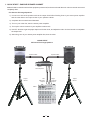
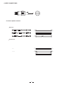
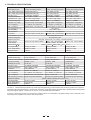
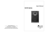
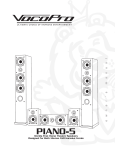
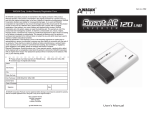
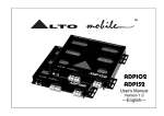
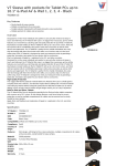
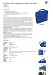
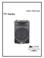
User's Manual
PS Series
R
LTO
www.altoproaudio.com
Version 1.0 January 2004
English
SAFETY INSTRUCTIONS
CAUTION
RISK OF ELECTRIC SHOCK
DO NOT OPEN
"Electric discharge"
This symbol, alert you to the presence of uninsulated dangerous voltage inside the product enclosure, which constitutes a
risk of electric shock.
"Exclamatory point"
This symbol, alert the user to the presence of important operating and maintenance instructions in the owner's manual
included to the product.
1. Read Instructions
All the safety and operation instructions should be read before using the product and retain them for future reference.
2. Water & Moisture
This product should not be used near water and will be protect from atmospheric agents in fixed or temporary installations.
3. Heat
This product should be situated away from heat sources such as radiators, or other devices which produce heat.
4. Liquid Entry
Care should be taken so that liquids are not spilled into the product and that objects do not fall on.
5. Service Assistance
This product should be serviced only by qualified service personnel when :
a. Liquids has spilled or objects have fallen into this product, or
b. This product has been exposed to rain, or
c. This product does not appear to operate normally or exhibits change in performance, or has been dropped or its
cabinet / chassis damaged.
6. Package
The package of this product has been tested, inspect the package before open, if any damage is found, notify to
your dealer.
7. Hearing
This product produce high acoustic levels may cause permanent hearing loss, (SPL in for a defined period of time).
8. Installations
This product should be installed on the wall or in the floor with specific stands, according to the max weight.
1
TABLE OF CONTENT
1. QUICK START - PASSIVE SPEAKER CABINET....................................................................................3
-. For Passive Full-range Speakers
2. QUICK START - ACTIVE SPEAKER CABINET.....................................................................................4
-. For Active Speaker Cabinets
3. CONNECTION PLATE...........................................................................................................................5
-. ACTIVE SPEAKER CABINET PS 4HA
-. PASSIVE FULL-RANGE SPEAKER PS 4H
-. ACTIVE SPEAKER CABINET PS 4LA
-. PASSIVE FULL-RANGE SPEAKER PS 4L
-. ACTIVE SPEAKER CABINET PS 3A
-. PASSIVE FULL-RANGE SPEAKER PS 3
4. WIRE CONNECTIONS ...........................................................................................................................8
-. For Passive Speaker Cabinets
-. For Active Speaker Cabinets
5. SUSPENSION POINT ............................................................................................................................8
6. TECHNICAL SPECIFICATIONS..............................................................................................................9
2
1. QUICK START - PASSIVE SPEAKER CABINET
Make all initial connections with all the equipment powered off, and ensure that all the main volume controls are turned
completely down.
-. For Passive Full-range Speakers
1). Connect one side of the speaker cable to the output CHA/CHB or Binding Post of your stereo power amplifier
and the other side to the input socket of your speaker cabinet.
2). Complete other connections as illustrated.
3). Turn on your mixer first, then the stereo power amplifier.
4). Turn up the volume controls of your amplifier to about 70%.
5). Use PFL function to get the proper input level for the mixer, and adjust the main mix level control to manipulate
the output level.
6). After using, turn off your stereo power amplifier first, then the mixer.
QUICK START
PS Passive Full-range Speakers
Speaker Cable
Speaker Cable
Stereo
Power Amplifier
Left
Main Mix
Output
Tripod
Mount
Right
Main Mix
Output
Mixer
3
Tripod
Mount
2. QUICK START - ACTIVE SPEAKER CABINET
Make all initial connections with all the equipment powered off, and ensure that all the main volume controls are turned
completely down.
-. For Active Speaker Cabinets
1). Connect one side of the signal cable at your audio mixer into output left /right (with Stereo-Jack or XLR) and
the other side of the cable into the line input (COMBO) of your active speaker cabinet (with Stereo-Jack or
XLR).
2). Connect the power cord to mains.
3). Turn on your mixer first, then the active speaker cabinets.
4). Turn up the volume control of the active speaker cabinets.
5). Use PFL function to get the proper input level for the mixer, and adjust the main mix level control to manipulate the
output level.
6). After using, turn off your active speaker cabinets first, then the mixer.
QUICK START
PS Active Full-range Speakers
Signal Cable
Signal Cable
Power Cord
Power Cord
Tripod
Mount
Right
Main Mix
Output
Left
Main Mix
Output
Tripod
Mount
Mixer
4
(6) (5)(4) (7)
3. CONNECTION PLATE
-. ACTIVE SPEAKER CABINET PS 4HA
VOLUME
PUSH
(1) BI-POLAR MAIN POWER SWITCH
MAX
NEW
2
MIN
L
I
N
E
TIDE
1
M
I
C
R
LTO
3
MIN
(2) AC POWER SOCKET WITH MAIN FUSE
INPUT
LINK
MAX
PS 4HA
SIGNAL
LIMIT
ACTIVE SPEAKER CABINET
BI-AMP. POWER AMPLIFIER
DSP PROCESSOR
BAL
SHIELD
(3) GROUND SWITCH
(4) SIGNAL LIMIT, GREEN/RED LED
(5) LINK OUT ON XLR CONNECTOR
(6) LINE /MIC INPUT ON COMBO CONNECTOR
(7) MAIN VOLUME CONTROL
"WARNING" TO REDUCE THE RISK OF FIRE OR ELECTRIC SHOCK DO NOT EXPOSE THIS PRODUCT TO RAIN OR MOISTURE.
230V
50Hz
MODEL
POWER
SERIAL
Use only with a 250V fuse
(2)
- PASSIVE FULL-RANGE SPEAKER PS 4H
(1)
LTO
R
PS 4H
(1) INPUT: Receive the power coming from an external
power amplifier (SPK +1/-1 connected; +2/-2
not connected).
(2) THRU: Direct LINK for connect in parallel a second
speaker cabinet (SPK +1/-1 connected; +2/-2
not connected).
SOUND REINFORCEMENT SPEAKER SYSTEM
POWER HANDLING:
AES - 250 Watts
PEAK - 500 Watts
IMPEDANCE:
Besides, the passive crossover included the electronic
protection on the driver.
8 ohms nominal
MODEL
SERIAL
DESIGNED AND DEVELOPMENT IN ITALY
INPUT
THRU
LINK
(1)
5
(2)
(3)
(6) (5)(4) (7)
-. ACTIVE SPEAKER CABINET PS 4LA
(1) BI-POLAR MAIN POWER SWITCH
(2) AC POWER SOCKET WITH MAIN FUSE
VOLUME
R
LTO
(3) GROUND SWITCH
SIGNAL
LIMIT
(3)
(4) CLIP INDICATOR RED LED
(5) LINK OUT ON XLR CONNECTOR
(6) STEREO JACK INPUT
(7) MAIN VOLUME CONTROL
"WARNING" TO REDUCE THE RISK OF FIRE OR ELECTRIC SHOCK DO NOT EXPOSE THIS PRODUCT TO RAIN OR MOISTURE.
MODEL
POWER
SERIAL
(2)
(1)
- PASSIVE FULL-RANGE SPEAKER PS 4L
LTO
R
(1) INPUT: Receive the power coming from an external
power amplifier (SPK +1/-1 connected; +2/-2
not connected).
(2) THRU: Direct LINK for connect in parallel a second
speaker cabinet (SPK +1/-1 connected; +2/-2
not connected).
PS 4L
SOUND REINFORCEMENT SPEAKER SYSTEM
POWER HANDLING:
AES - 180 Watts
PEAK - 360 Watts
IMPEDANCE:
Besides, the passive crossover included the electronic
protection on the driver.
8 ohms nominal
MODEL
SERIAL
DESIGNED AND DEVELOPMENT IN ITALY
INPUT
THRU
LINK
(1)
6
(2)
(6) (5)(4) (7)
-. ACTIVE SPEAKER CABINET PS 3A
(1) BI-POLAR MAIN POWER SWITCH
(2) AC POWER SOCKET WITH MAIN FUSE
VOLUME
(3) GROUND SWITCH
R
LTO
+4dBu
INPUT
(4) CLIP INDICATOR RED LED
LINK
PS 3A
CLIP
ACTIVE SPEAKER CABINET
BI-AMP. POWER AMPLIFIER
BAL
SHIELD
(5) LINK OUT ON XLR CONNECTOR
(6) STEREO JACK INPUT
(7) MAIN VOLUME CONTROL
"WARNING" TO REDUCE THE RISK OF FIRE OR ELECTRIC SHOCK DO NOT EXPOSE THIS PRODUCT TO RAIN OR MOISTURE.
220-240V
MODEL
50/60Hz
POWER
SERIAL
Use only with a 250V fuse
(2)
- PASSIVE FULL-RANGE SPEAKER PS 3
(1)
LTO
R
PS 3
(1) INPUT: Receive the power coming from an external
power amplifier (SPK +1/-1 connected; +2/-2
not connected).
(2) THRU: Direct LINK for connect in parallel a second
speaker cabinet (SPK +1/-1 connected; +2/-2
not connected).
SOUND REINFORCEMENT SPEAKER SYSTEM
POWER HANDLING:
AES - 120 Watts
PEAK - 240 Watts
IMPEDANCE:
Besides, the passive crossover included the electronic
protection on the driver.
8 ohms nominal
MODEL
SERIAL
DESIGNED AND DEVELOPMENT IN ITALY
INPUT
THRU
LINK
(1)
7
(2)
(3)
4. WIRE CONNECTIONS
2-
1-
1+
2+
-. For Active Speaker Cabinets
Balanced
TIP RING SLEEVE
Tip
Ring
Sleeve
SLEEVE RING TIP
3
2
2
3
1
1
1
3
2
TIP RING SLEEVE
Tip
Ring
Sleeve
1
2
1
2
3
3
Tip
Ring
1
2
3
Sleeve
Unbalanced
Tip
TIP SLEEVE
Sleeve
TIP RING SLEEVE
Sleeve
Tip
Ring
1
2
3
8
Tip
Sleeve
Tip
Ring
Sleeve
1
2
3
6. TECHNICAL SPECIFICATIONS
PS4HA Active
Bi-Amp. with DSP processor
300Watt RMS Class H
100Watt RMS Class AB
121.5dB SPL calculated
50Hz / 20kHz +/-10dB
Low 4 Ohm - High 8 Ohm
2000Hz - DSP Processor
DSP Lim./ Comp. each sections
12" / 318mm - 2.5" voice coil
Titanium Driver 1.35" Voice Coil
Descriptions
Active System type
LOW - RMS Output Power
HIGH - RMS Output Power
Max SPL at 1m
Frequency Response
Impedance Low - High
Crossover Frequency
Protection Low - High
Low - Frequency
High - Frequency
Horn Coverage H x V
Input Sensitivity
Input Impedance
Connectors
Plastic Reinforced Cabinet
Hardware Suspension
Amplifier Protections
External Control
Power Supply
Dimensions H W D
Net Weight lbs/kg
Gross Weight lbs/kg
Shipping Volume
PS4LA Active
PS3A Active
Bi-Amp. with analog processor
Bi-Amp. with analog processor
150W RMS Class AB
70W RMS Class AB
50W RMS Class AB
50W RMS Class AB
118.5dB SPL calculated
115.5dB SPL calculated
55Hz / 20kHz +/-10dB
60Hz / 20kHz +/-10dB
Low 4 Ohm - High 8 Ohm
Low 4 Ohm - High 8 Ohm
2500Hz 6 / 12dB/Oct.
3000Hz 6 / 12dB/Oct.
Analog Limiter / Compressor
Analog Limiter / Compressor
12" / 318mm - 2" voice coil
12" / 318mm - 2" voice coil
Aluminum Driver 1" Voice Coil
Aluminum Driver 1" Voice Coil
90 H x45 V
Line + 4dB / 1.23 V
30k Balanced -15k Unbalanced
Input with Combo/ Link with XLR
Input with Jack / Link with XLR Input with Jack / Link with XLR
Trapezoidal & Monitor shape
Six suspension point
Soft Start - Short Circuit - DC voltage - Thermal Protection
Mic/Line Vol.-Clip-Ground Switch. Volume- Clip - Ground Switch
Volume- Clip - Ground Switch
230Volt / 115Volt 50 / 60Hz
660mm 396mm 384mm (26" 15.6" 15.1")
23.38kg / 51.54lbs
19.40kg / 42.76lbs
19.2kg / 42.32lbs
26.06kg / 57.38lbs
22.05kg / 48.61lbs
21.85kg / 47.17lbs
4.83CFT
4.83CFT
4.83CFT
Descriptions
Passive System type
Continuos Power Handling
Peak Power Rating
Sensitivity at 1W,1mt
Max SPL at 1mt
Frequency Response
Impedance
Crossover Frequency
Low - Frequency
High - Frequency
High Frequency Protection
Dimensions HxWxD
Net Weight lbs/kg
Gross Weight lbs/kg
Shipping Volume
PS4H Passive
PS4L Passive
PS3 Passive
2-way vented box
2-way vented box
2-way vented box
250Watt AES Standard
180Watt AES Standard
120Watt AES Standard
500Watt Peak
360Watt Peak
240Watt Peak
97 dB SPL
96 dB SPL
95 dB SPL
115 dB SPL Calculated
121 dB SPL Calculated
118.5 dB SPL Calculated
65Hz / 20kHz +/-10dB
55Hz / 20kHz +/-10dB
60Hz / 20kHz +/-10dB
8 Ohm Nominal
8 Ohm Nominal
8 Ohm Nominal
3000Hz 6 / 12dB/Oct
2000Hz 12 / 24dB/Oct
2250Hz 6 / 12dB/Oct
12" / 318mm - 2" voice coil
12" / 318mm - 2.5" voice coil
12" / 318mm - 2" voice coil
Driver 1" Voice Coil
Titanium Driver 1.35" Voice Coil
Driver 1" Voice Coil
Electronic Dynamic Protection
Electronic Dynamic Protection
Electronic Dynamic Protection
660mm x396mmx 384mm (26" x15.6" x15.1")
17.3kg / 38.13lbs
17.12kg / 37.74lbs
18.75kg /41.34lbs
19.95kg / 43.98lbs
22kg / 48.5lbs
22kg / 48.5lbs
4.83CFT
4.83CFT
4.83CFT
The AES 2 - 1984 Standard specification by Audio Engineering Society, is representative and commonly used for the measure in
Professional Sound Reinforcement. It is defined as the square of the RMS voltage generated with a pre-defined and band-passed
Pink Noise Signal, applied continuously for 2 hours, on the assembled speaker cabinet.
In this way, the declared power of ALTO passive speaker cabinet, is comparable to the RMS voltage value, measured on the
equivalent power amplifier for the same value of impedance.
9
SEIKAKU TECHNICAL GROUP LIMITED
No. 1, Lane 17, Sec. 2, Han Shi W. Road, Taichung, 401 Taiwan
http://www.altomobile.com Tel: 886-4-22313737
email: [email protected] Fax: 886-4-22346757
All rights reserved to ALTO Mobile. Due to continued development in response to
customer feedback, product features, specifications and/or internal/external design may be
changed without prior notice. No photocopying, translation or reproduction of any part of this user
manual is allowed without prior written permission.Copyright c 2004 Seikaku Technical Group Limited.
NF01702-1.1