1
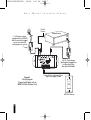
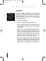
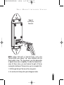
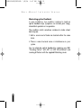
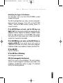
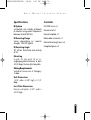
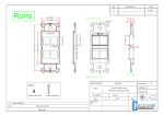
DS00331ACN/WS100R
1/8/04
9:47 AM
Page 2
I N S TA L L AT I O N & O P E R AT I O N G U I D E
WS100R
WALL-MOUNT INFRARED SENSOR
B
L E N D I N G
H
I G H
F
I D E L I T Y
A N D
A
R C H I T E C T U R E
®
DS00331ACN/WS100R
1/8/04
W
9:47 AM
A L L
- M
Page 3
O U N T
I
N F R A R E D
S
E N S O R
WS100R
Wall-Mount
Infrared Sensor
Introduction
TABLE OF CONTENTS
Introduction
1
Features and
Benefits
2
Installation
Considerations
3
Installation
9
Operation
11
Troubleshooting
12
Specifications
16
Contents
16
The WS100R is a wall-mount, Decora ® style IR sensor
designed for use with the Niles infrared extender systems.
Installed in a remote room location, the WS100R receives the
IR commands transmitted from your existing hand-held
remotes in that room. The commands are carried via a
category 5 cable to your A/V equipment in another room,
and instantly “repeated”.
The WS100R is compatible with all current Niles infrared
systems. It may be used along with, or as an alternative to,
the Niles TS100, MS100, MS200, MVC100IR and CS100
sensors or the IntelliPad®.
The WS100R is just one part of the three building blocks
necessary to complete a Niles IR repeating system:
• IR Main System Unit—Models MSU140, MSU250, MSU480
and MSU440Z.
• IR Sensors/Keypads—Models WS100, TS100, MS100,
MS200, CS100, MVC100IR and the IntelliPad®.
• IR Flashers—Models MF1, MF2, MF1FV, MF2FV and the IRB1.
An IR sensor expansion hub, Model IRH610, is available to
provide additional sensor inputs to your system.
®
DS00331ACN/WS100R
1/8/04
W
A L L
9:47 AM
- M
O U N T
Page 4
I
N F R A R E D
S
E N S O R
Features and Benefits
The WS100R offers a number of improvements over
other wall-mount IR sensors.
• Plasma-proof performance— allows placement of the
WS100R near plasma displays.
• CFL interference resistant— expands installation flexibility to areas with fluorescent lighting.
• Works under most lighting conditions, including indirect sunlight— eliminates environmental restrictions.
• Universal system— compatible with virtually all
brands of A/V equipment and remote controls.
• Excellent IR receiving range— you get 18' to 30' of
remote control range (depending upon the strength
of your handheld remote).
• 100% factory tested for pickup range and angle.
• Small size of only 2-3/4" wide by 4-1/2" high by
1-1/4"— fits in a one-gang box.
• Printed circuit board design uses surface mount technology (SMT), assuring high reliability.
• Ideal for both home and commercial installations.
• Removable Decora-style snap-in color insert.
(Available in four colors).
• Two year parts and labor warranty.
2
DS00331ACN/WS100R
1/8/04
W
A L L
9:47 AM
- M
O U N T
Page 5
I
N F R A R E D
S
E N S O R
Installation Considerations
The WS100R is a Decora-style module and is designed to use
standard Decora-style cover plates and mounting hardware.
Decora cover plates (up to 6-gang) with color-matched plate
screws are available from your Niles dealer.
Type of Cable
The WS100R connects to the Niles infrared main systems unit
or IRH610 sensor expansion hub with an individual home run
of category 5 cable. When running wires inside walls, most
states and municipalities in the U.S. specify that you must use
a special type of wire. Usually, the requirement is that the
wire has a specific “CL” fire rating, such as “CL-2” or “CL-3”.
Consult your Niles dealer, building contractor, or local building and inspection department if unsure about which type of
wire is best for your application.
WS100R Mounting Location
Locating the WS100R in the center of a room usually results
in the most even IR receiving coverage, especially if the room
is square shaped. Rooms that are L-shaped or long and
narrow require more careful consideration. With these types
of rooms, installing the WS100R closest to the primary location of the user will ensure the best performance.
Receiving Range and Pickup Angle
The receiving range of the WS100R will vary according to the
IR output strength of the remote control being used. Remote
strength varies among brands depending on the number
and size of batteries used, and how many IR emitters the
remote has. For example, remotes that operate on two small
AAA batteries and have only one IR emitter are generally not
3
DS00331ACN/WS100R
1/8/04
W
A L L
9:47 AM
- M
O U N T
Page 6
I
N F R A R E D
S
as strong as remotes that use the larger AA size batteries and
have two emitters. Tests with various manufacturers’ remote
controls have shown that the operating range can vary from
a minimum of 18' to a maximum of about 30'.
Infrared signals travel essentially line-of-sight. They will not
pass through or around solid objects. Do not rely on an IR
signal being able to “bounce” off a wall or object to the
WS100R.
The IR pickup angle of the WS100R is 30° off-axis
(horizontal and vertical) at 18'.
E N S O R
TOOLS
REQUIRED
• 1/8" Standard
Slotted Screwdriver
• 1/4" Standard
Slotted Screwdriver
• Wire Stripper
Junction Boxes
The mounting depth of the WS100R is 1-1/4". When
installed, the unit extends 3/4" behind the sheetrock
wall (assuming 1/2" sheetrock). Suitable electrical boxes
are available from your Niles dealer or local electrical
supply company.
DO NOT INSTALL THE WS100R INTO ELECTRICAL
BOXES WITH 110 VOLT DEVICES.
Some states or municipalities allow devices such as the
WS100R to be installed into the same electrical box as
110 volt devices, provided a “low-voltage partition” is used
between the devices. We do not recommend this. The cable
connected to the WS100R can act as an “antenna” for electrical noise. Locating the WS100R cable too close to a light
dimmer or switch may interfere with the WS100R.
If you must locate the WS100R near electrical devices, install
it in a separate metal electrical box, ground the box to the
electrical system ground, and route the WS100R cable
several feet away from all electrical wiring.
4
DS00331ACN/WS100R
1/8/04
W
A L L
9:47 AM
- M
O U N T
Page 7
I
N F R A R E D
S
E N S O R
Niles IR
Flasher
Stereo Receiver
12V DC power supply
(supplied with the MSU250
Main System Unit) plugged
into an unswitched AC
outlet powers the system
3-30V
AC/DC
STATUS
IN
12V DC Power Supply
(Not Supplied) plugged into
the Switched Outlet
Niles Stock# FG000665
MSU250
Figure 1
Wiring Diagram
(Typical installation with an
MSU250 Main System Unit)
Power, IR Data, and Power Status
Signal via category 5 cable
WS100 IR Sensor
5
DS00331ACN/WS100R
1/8/04
W
A L L
9:47 AM
- M
Page 8
O U N T
I
S
N F R A R E D
E N S O R
Figure 2
WS100R Parts Guide
a
e
g
b
c
f
d
e
(a) Electrical Box
(b) Category 5 cable
(c) WS100 IR Receiver (supplied)
(d) Snap-on Color Insert (supplied)
(e) Device Screws (2 supplied)
(f) Decora Faceplate (supplied)
(g) Faceplate Screws (2 supplied)
g
6
DS00331ACN/WS100R
1/8/04
W
A L L
9:47 AM
- M
O U N T
Page 9
I
N F R A R E D
S
E N S O R
Avoiding Interference
The WS100R is designed to work in most applications
including plasma displays and in areas where CFL lighting
and indirect sunight are present. You should avoid locating
the WS100R near potential sources of electrical or optical
noise, such as light dimmers or low-voltage lights.
Avoiding Electrical Interference
Avoid locating the WS100R near any potential sources of
electrical or optical noise, such as light dimmers, low-voltage lights, and neon lights.
Figure 3
Removing the
Decora-style Insert
Avoiding Optical Feedback
If installing the WS100R in the same room as an IR flasher,
it is possible for the flasher’s IR output to be picked-up by
the WS100R. This effect, known as an optical feedback
loop, can cause erratic operation. Optical feedback is
similar to acoustical feedback: the howling or whistling
sound heard in a P.A. system when the microphone is too
close to the speaker. To avoid optical feedback:
1. Re-position the flasher(s) and/or the sensor.
“TECH TIP”
Do not exert
excessive pressure
on the plastic
mounting tabs.
2. Use Niles MF1or MF2 flashers and cover them with the
supplied IR blockers.
Changing the Color of the WS100R
The Decora-style insert on the WS100R is removable,
allowing fast and easy color changes as needed. Inserts are
available in a variety of colors.
If you need to change the color of the WS100R:
1. Obtain the WS100R Decora-style insert in the desired
color from your Niles dealer.
7
DS00331ACN/WS100R
1/8/04
W
A L L
9:47 AM
- M
O U N T
Page 10
I
N F R A R E D
S
E N S O R
2. Hold the WS100R as shown in (Figure 3). Locate the two
plastic mounting tabs at the top rear of the Decora-style
insert. Using two fingers, simultaneously press both tabs
down (towards the center of the insert) and forward (away
from you) until the insert pops free from its mounting slots.
3. Locate the new Decora-style insert. Hold the WS100R so that
it is facing you. Insert the two bottom tabs into the bottom
slots first, followed by the two tabs on the top. Snap the insert
into place by carefully pressing on the front of the insert.
Using the WS100R with the Intellipad Ci system.
The WS100R is fully compatible with the Niles Intellipad Ci line,
follow the wiring instructions in Figure 4. For specific information see your Intellipad Ci manual.
1 = Green/White - 12V
2 = Green - DATA
3 = Orange/White - GROUND
4 = Blue - EMPTY
5 = Blue/White - STATUS
6 = Orange - EMPTY
7 = Brown/White - EMPTY
8 = Brown - EMPTY
Tab
Down
5 = STATUS
3 = GROUND
1 = STATUS
2 = DATA
3 = GROUND
4 = 12V DC
1 = 12V
2 = DATA
Figure 4
This color code is based on the industry standard T568A coding
for the RJ45 connector. When connecting the WS100R to the
Niles Ci system observe this Pin configuration.
8
DS00331ACN/WS100R
1/8/04
W
A L L
9:47 AM
- M
O U N T
Page 11
I
N F R A R E D
S
E N S O R
Installation
“TECH TIP”
Avoid installing the
WS100R next to
a light dimmer.
If you are installing the WS100R into an existing wall,
take time to consider any possible obstructions which may be
hidden inside the wall, such as wood or metal studs,
electrical, telephone or other types of wiring, plumbing,
AC or heating conduit, etc.
1. Locate the connector plug.
2. Strip 1/4" of insulation from the end of each wire.
3. Use a small flathead screwdriver or your thumbnail to raise
the locking tabs, exposing the holes on the removable
connector plug.
4. Insert each wire into the appropriate hole on the removable connector plug, and snap the locking tab down. To
help you, the connector plug is keyed. Insert the smooth
side of the connector plug into the smooth side of the
socket. Don’t force the scalloped side of the connector
plug into the smooth side of the socket. (Figure 5)
5. Use the shorter plate screws to fasten the Decora cover
plate to the WS100R. DO NOT OVER-TIGHTEN THE PLATE
SCREWS OR YOU MAY DAMAGE THE COVER PLATE. Line
up all the screws in the same direction for a finished look.
9
DS00331ACN/WS100R
1/8/04
W
A L L
9:47 AM
- M
O U N T
Page 12
I
N F R A R E D
S
E N S O R
Figure 5
Installing the
Connector
NOTE: Certain “old work” or “retro-fit” boxes, such as the
Carlon B225R, have a plastic “lip” which interferes with the
Decora plate screws. This lip prevents you from being able
to tighten these screws completely. To make the clearance necessary for these screws, you must remove the parts of the lip
causing the interference. There are two ways to accomplish this:
1. Drill through the lip of the box at the screw points.
2. Cut notches into the lip with a pair of diagonal cutters.
10
DS00331ACN/WS100R
1/8/04
W
A L L
9:47 AM
- M
Page 13
O U N T
I
N F R A R E D
S
E N S O R
Intellipad Wiring
See your MSU manual if you are connecting the WS100R
with an IntelliPad system.
Operation
Operation of the WS100R is simple. Stand within the
operational range of your WS100R. Aim your hand-held
remote at the WS100R and press the button for the desired
command. Your IR command is instantly repeated to your
A/V equipment.
Green “Power Status” LED
When the WS100R is correctly connected (as shown in Figure 1),
the Green LED will stay lit as long as the preamp/receiver is
on. When your preamp/receiver is off, the LED will stay off.
Blue “Flash-back” LED
The blue “flash-back” LED on the WS100R visually confirms
the reception of an IR command.
11
DS00331ACN/WS100R
1/8/04
W
A L L
9:47 AM
- M
O U N T
Page 14
I
N F R A R E D
S
E N S O R
Troubleshooting
This manual contains instructions for the WS100R only. For
specific information on the adjustment and operation of your
Niles infrared extender system, please refer to the instruction
manual included with your Niles IR main system unit (MSU140,
MSU250, MSU480 MSU440Z, IntelliControl®).
The bi-color blue/green LED on the front of the WS100R is a
useful troubleshooting aid. The led should light solid green
when status is detected.
The blue LED should light only when a remote command is
being received. If the LED on the WS100R “flickers”, and the
WS100R functions normally, there is no cause for concern,
some stray IR signal are being received by the WS100R but are
not being repeated.
1. Test the remote control(s) by operating the A/V equipment
directly. Replace the batteries if needed.
2. Double check the cable connections on all WS100R’s and on
the main system unit. Look for open, shorted or reversed wires.
3. Test for interference from the following sources:
• Neon or halogen lights in the room.
• Light dimmers, beginning with those closest to the
WS100R.
Observe the WS100R’s LED while performing all the tests. It is
possible to have interference from more than one source.
12
DS00331ACN/WS100R
1/8/04
W
A L L
9:47 AM
- M
O U N T
Page 15
I
N F R A R E D
S
E N S O R
Eliminating optical feedback
In some installations, two conditions combine to create an
optical feedback loop. Symptoms can include: poor range,
intermittent operation or no operation.
The conditions which sometimes combine to create a feedback loop are:
1. Both a sensor and a flasher are located within the same
room.
2. There is some low-level noise or interference on your
system.
You can eliminate optical feedback by replacing any IRB1
“flooding flasher” with MF1 or MF2 MicroFlashers and
covering all flashers with the supplied IR blocking covers.
13
DS00331ACN/WS100R
1/8/04
W
A L L
9:47 AM
- M
O U N T
Page 16
I
N F R A R E D
S
E N S O R
Identifying the type of interference
The “flash-back” LED on the front of the WS100R is a useful
trouble-shooting aid.
The LED should light blue only when a remote command is
being received. However, if the LED on the WS100R
“flickers”, and the WS100R functions normally, there is no
cause for concern.
If the WS100R does not work, and the LED does not
light at all: Test the remote control(s) by operating the A/V
equipment directly. Replace the batteries if needed. Double
check the cable connections on all WS100R’s Main System
Unit and on the IR main system unit. Consult your IR Main
System Unit’s manual for more detail.
If the WS100R does not work, and the LED flickers or
remains solidly lit: Cover up the Sensor with a piece of
cardboard (your hand will actually create electromagnetic
interference under some conditions). Observe the IR test LED.
IR Test LED Off:
Optical Interference.
IR Test LED On or Flickering:
Electromagnetic Interference.
EMI (Electromagnetic Interference)
Identify the source of the interference. The most common
sources of electromagnetic interference are listed in the
Installation Considerations section on page 3. To eliminate
EMI try the following methods:
14
DS00331ACN/WS100R
1/8/04
W
A L L
9:47 AM
- M
Page 17
O U N T
I
N F R A R E D
S
E N S O R
1. Move the sensor or the sensor cable away from the EMI
source or move the source of the EMI away from the
sensor or the cable.
2. Connect the Sensor’s GND terminal to true earth
ground (if this isn’t feasible use the main system unit’s
GND terminal).
There are many methods for reducing interference. Which
solution is best for you depends on your situation. If you
require further assistance contact Niles Technical Support at
1-800-289-4434.
TECH NOTE
The feedback LED can be disabled if it continues to flicker or
visual feedback is not desired. Discrete on and off IR commands are available on the Niles Technical support website
for disabling the feedback LED. The address is:
nilesaudio.com/techsupport.
15
DS00331ACN/WS100R
1/8/04
W
A L L
9:47 AM
- M
O U N T
Page 18
I
N F R A R E D
S
E N S O R
Specifications
Contents
IR System
Compatible with virtually all brands
of remotes using carrier frequencies
between 26 and 105 kHz.
WS100R Sensor x1
IR Receiving Range
Varies depending on remote
strength; 18 to 30' typical.
Removable connector x 1
IR Receiving Angle
30° off-axis (horizontal and vertical)
at 18'.
Faceplate Spaces x 2
Decora Insert x1
Decora faceplate x 1
Device Mounting Screws x 2
Mounting
In-wall, fits into most 18 cu. in.
single-gang electrical boxes at least
2-3/4" deep, Decora-style face plate.
Wiring Requirements
Individual home-runs of Category
5 cable.
Unit Dimensions
1-5/8" wide x 2-5/8" high x 1-1/4"
deep.
Face Plate Dimensions
Decora wall plate; 2-3/4" wide x
4-1/2" high.
16
DS00331ACN/WS100R
1/8/04
W
Notes
17
A L L
9:47 AM
- M
O U N T
Page 19
I
N F R A R E D
S
E N S O R
DS00331ACN/WS100R
1/8/04
W
A L L
9:47 AM
- M
O U N T
Page 20
I
N F R A R E D
S
E N S O R
Notes
18
DS00331ACN/WS100R
1/8/04
9:47 AM
Page 1
®
Niles Audio
Corporation
www.nilesaudio.com
12331 S.W. 130 Street
Miami, Florida 33186
Tel: (305) 238-4373
Fax: (305) 238-0185
©2004 Niles Audio Corporation. All rights reserved. Niles, the Niles logo, IntelliPad and Blending High Fidelity and
Architecture are registered trademarks of Niles Audio Corporation. MicroFlasher is a trademark of Niles Audio
Corporation. Because we strive to improve our products. All other trademarks are the property of their respective
owners. Niles reserves the right to change product specifications without notice. The technical and other information contained herein is not intended to set forth all technical and other specifications of Niles products.
Additional information can be obtained on-line at www.nilesaudio.com or by calling Niles at 1-800-289-4434.
01/04 Printed in China DS00331ACN