1
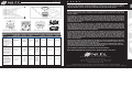
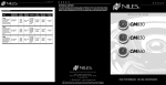
TECHNICAL SUPPORT
IF YOU HAVE QUESTIONS ABOUT THE INSTALLATION OR OPERATION OF THIS OR ANY OTHER NILES PRODUCT,
PLEASE CALL OUR TECHNICAL SUPPORT DEPARTMENT AT 1-800-BUY-HIFI (1-800-289-4434). SUPPORT IS
AVAILABLE WEEKDAYS 8:00 A.M. TO 7:00 P.M. EASTERN TIME WITH THE EXCEPTION OF HOLIDAYS.
LIMITED WARRANTY
I N S TA L L AT I O N G U I D E
NILES AUDIO CORPORATION (“NILES”) WARRANTS ITS LOUDSPEAKER PRODUCTS TO THE ORIGINAL PURCHASER TO
BE FREE OF MANUFACTURING DEFECTS IN MATERIAL AND WORKMANSHIP FOR A PERIOD OF FIVE YEARS FROM
DATE OF PURCHASE.
Figure 1. Typical placement for stereo listening.
THIS WARRANTY IS SUBJECT TO THE FOLLOWING ADDITIONAL CONDITIONS AND LIMITATIONS. THE WARRANTY
IS VOID AND INAPPLICABLE IF NILES DEEMS THAT THE PRODUCT HAS BEEN USED OR HANDLED OTHER THAN IN
ACCORDANCE WITH THE INSTRUCTIONS PROVIDED BY THE MANUFACTURER, INCLUDING BUT NOT LIMITED TO
DAMAGE CAUSED BY ACCIDENT, MISHANDLING, IMPROPER INSTALLATION, ABUSE, NEGLIGENCE, OR NORMAL
WEAR AND TEAR, OR ANY DEFECT CAUSED BY REPAIR TO THE PRODUCT BY ANYONE OTHER THAN NILES OR AN
AUTHORIZED NILES DEALER.
Figure 2. New construction bracket.
Figure 6. Treble level control.
Figure 3. Installing the loudspeaker.
Figure 4. Tweeter adjustment.
Figure 5. Woofer adjustment. Figure 7. Presence level control.
SPECIFICATIONS
Model
Recommended
Normal
Amplifier Power Impedance
Frequency
Response
Sensitivity
55Hz - 21kHz
+/-3dB
90 dB with
2.83 V pink
noise input
measured
at 1 meter
on axis
Frame
Hole Cut-Out Depth Behind
Dimensions Dimensions
Ceiling
CM730DS
Twist and Lock™
mechanism with Directed
Soundfield™ patented
fully pivoting assembly
featuring one 7"
polypropylene woofer with
butyl rubber surround and
one 1" UltraSilk™ tweeter
with fluid cooling.
10 to 125 watts
per channel
8 ohm
nominal;
6 ohm
minimum
11 inches
9-3/4 inches
5-3/4 inches
IF THE ABOVE CONDITIONS ARE MET, THE PURCHASER’S SOLE REMEDY SHALL BE TO RETURN THE PRODUCT TO
NILES, IN WHICH CASE NILES WILL REPAIR OR REPLACE, AT ITS SOLE OPTION, THE DEFECTIVE PRODUCT WITHOUT
CHARGE FOR PARTS OR LABOR. NILES WILL RETURN A UNIT REPAIRED OR REPLACED UNDER WARRANTY BY
SHIPPING SAME BY ITS USUAL SHIPPING METHOD FROM THE FACTORY (ONLY) AT ITS EXPENSE WITHIN THE
UNITED STATES OF AMERICA. THERE ARE NO OTHER WARRANTIES, INCLUDING WITHOUT LIMITATION, EITHER
EXPRESS OR IMPLIED WARRANTIES OF MERCHANTABILITY OR FITNESS FOR A PARTICULAR PURPOSE, WITH
RESPECT TO THE PRODUCT.
REPAIR OR REPLACEMENT AS PROVIDED UNDER THIS WARRANTY IS THE EXCLUSIVE REMEDY OF THE CONSUMER/
PURCHASER. NILES SHALL NOT BE RESPONSIBLE FOR ANY INCIDENTAL OR CONSEQUENTIAL DAMAGES EXCEPT TO
THE EXTENT PROVIDED (OR PROHIBITED) BY APPLICABLE LAW.
CM750DS
CM760DS
SOME STATES DO NOT ALLOW THE EXCLUSION OR LIMITATION OF INCIDENTAL OR CONSEQUENTIAL DAMAGES,
SO THE ABOVE LIMITATION MAY NOT APPLY TO YOU. THIS WARRANTY GIVES YOU SPECIFIC LEGAL RIGHTS, AND
YOU MAY ALSO HAVE OTHER RIGHTS WHICH VARY FROM STATE TO STATE.
CM750DS
Twist and Lock™
mechanism with Directed
Soundfield™ patented
fully pivoting assembly
featuring one 7" Injectionmolded TCC™ woofer
with butyl rubber surround
and one 1" Teteron®
tweeter with fluid cooling.
TO OBTAIN WARRANTY SERVICE, TAKE THE UNIT TO THE NEAREST AUTHORIZED NILES DEALER, WHO WILL
TEST THE PRODUCT AND IF NECESSARY, FORWARD IT TO NILES FOR SERVICE. IF THERE ARE NO AUTHORIZED
NILES DEALERS IN YOUR AREA, YOU MUST WRITE TO NILES AND INCLUDE YOUR NAME, ADDRESS, MODEL AND
SERIAL NUMBER OF YOUR UNIT, ALONG WITH A BRIEF DESCRIPTION OF THE PROBLEM. A FACTORY RETURN
AUTHORIZATION NUMBER WILL BE SENT TO YOU. DO NOT RETURN ANY UNIT WITHOUT FIRST RECEIVING WRITTEN
AUTHORIZATION AND SHIPPING INSTRUCTIONS FROM NILES.
CM730DS
10 to 125 watts
per channel
8 ohm
nominal;
6 ohm
minimum
52Hz - 21kHz
+/-3dB
90 dB with
2.83 V pink
noise input
measured
at 1 meter
on axis
48Hz - 21kHz
+/-3dB
90 dB with
2.83 V pink
noise input
measured
at 1 meter
on axis
FOR THE NAME OF YOUR NEAREST AUTHORIZED NILES DEALER CONTACT:
11 inches
9-3/4 inches
5-7/8 inches
NILES AUDIO CORPORATION, P.O. BOX 160818, MIAMI, FLORIDA 33116-0818.
CM760DS
Twist and Lock™
mechanism with
Directed Soundfield™
patented fully pivoting
assembly featuring one
7" Interlaced glass fiber
woofer with butyl rubber
surround and one 1"
Teteron® tweeter with
fluid cooling.
10 to 150 watts
per channel
8 ohm
nominal;
6 ohm
minimum
BLENDING HIGH FIDELITY AND ARCHITECTURE®
11 inches
9-3/4 inches
5-7/8 inches
Niles Audio Corporation
1 2 3 3 1 S . W. 1 3 0 S t r e e t M i a m i , F l o r i d a 3 3 1 8 6
Phone: 305-238-4373 Fax: (305) 238-0185
www.nilesaudio.com
©2007 N i l es Aud i o C orporation . A ll righ ts re se r v e d. Nile s an d th e Nile s logos are re giste re d trade marks
of N i l es Aud i o C orp ora t i on. Al l ot her trade marks are th e prope rty of th e ir re spe ctiv e own e rs. U .S. P ate n t # 6 ,6 8 3 ,9 6 3 . D S 0 0 5 3 7 A
HIGH PERFORMANCE CEILING LOUDSPEAKERS
CONGRATULATIONS!
Thank you for choosing a CM730DS, CM750DS or CM760DS loudspeaker from Niles. With proper installation and operation, you will enjoy
years of trouble-free use. Niles manufactures the industry’s most complete line of custom installation components and accessories for
audio/video systems. To see the complete Niles product assortment, visit us on the Internet at: www.nilesaudio.com
PACKAGE CONTENTS
Each package contains one pair of CM730DS, CM750DS or CM760DS loudspeakers; 1 pair of Aluminum MicroPerf™ Grilles and 1 pair of
cardboard paint mask/hole cutout templates.
INSTALLATION CONSIDERATIONS
We recommend using the following tools and material to install your Niles CM loudspeaker:
• Cordless drill with 1/4 – and 1/2inch drill bits and a 1-inch paddle
drill bit (for drilling through studs)
• Stiff wire, fish tape or glow rods
for routing cables
• Rubber gloves and protective
eyewear
• Keyhole or drywall saw
3. Cut a foot-long piece of coat hanger. Bend the wire (creating a right angle) leaving 5-1/2” at one end (this allows for the extra width of
the mounting dogs). Poke the “L-shaped” wire into the pilot hole and turn it in a complete circle and move it into the ceiling cavity to
make sure you have approximately 4-3/8” of depth. If the wire’s movement is obstructed by anything, fill the hole(s) with spackle and try
another location.
4. If the coat hanger moves freely in a complete circle and you have sufficient depth, hold the template up to the ceiling surface. The
cardboard square with the circular hole is the template. The inner perforated circle within the larger circle that was removed in step 1
earlier is the paint mask. Keep it for painting the loudspeaker later. Outline the circular cutout on the ceiling surface lightly with a pencil.
Drill the starting point of your cut with a 1/4” bit.
5. If you are cutting drywall use a sheetrock or keyhole saw, cut the hole with the saw at a 45° angle. That way the drywall section can be
replaced cleanly if there is an unseen obstruction behind the wall.
IMPORTANT: BE VERY CAREFUL NOT TO SAW THROUGH EXISTING WIRES, PIPES, OR STRUCTURE.
IF YOU FEEL EXTRA RESISTANCE AS YOU ARE CUTTING, STOP.
• Phillips screwdriver set
• Wire stripper
NEW CONSTRUCTION INSTALLATION
• Stud finder
INSULATING THE WALL CAVITY
• Cable ties
If feasible, fill the wall cavity with insulation at this point.
• Pencil
MOUNTING THE NEW CONSTRUCTION BRACKET
Before starting the installation, please observe the following precautions:
• Turn off all system power before
making any connections
• Make sure hands are clean before
installation
• Always wear protective eyewear
when using tools
• Wear gloves when working with
fiberglass insulation
RUNNING WIRES IN WALLS OR CEILINGS
When running loudspeaker wire inside walls or ceilings, use special jacketed cable (a minimum of 16-gauge two-conductor CL-2 or CL-3
rated loudspeaker wire) to protect the wire and for fire prevention. In some areas, conduit is also required. For a trouble-free installation,
low-voltage wire such as loudspeaker wire must be run in accordance with the National Electrical Code and any applicable provisions of
the local building code. If you are unsure of the correct installation techniques, wire jacket, or type of conduit to use, consult a professional
audio/video installer, building contractor, or the local building and inspection department.
SELECTING THE LOCATION FOR YOUR LOUDSPEAKERS
The CM700DS series loudspeakers are designed to be installed in any standard ceiling. There are two considerations for placing the
loudspeaker; ease of running the cable to the loudspeaker and coverage of the loudspeaker. The best stereo effect will be achieved if both
the loudspeakers are at equal distance from the listener and closer together than the listener is from the loudspeakers. Avoid installing the
loudspeakers near corners to prevent a “boomy” or diffracted sound. The CM700DS series loudspeakers will cover an area of a circle with
a 16-foot diameter when mounted at an 8-foot height and pointed straight down. (See Figure 1)
The optional CM700DS BKT can be used with the CM730DS, CM750DS or CM760DS loudspeakers. The hole saving bracket enables a
faster and cleaner final installation of the loudspeaker. It forces the drywall installer to cut out the loudspeaker hole for you and provides
wire ties for the loudspeaker wire, reducing the risks of accidental loss or movement of the wire. In addition, it enables you to align your
loudspeakers with other ceiling fixtures with great accuracy since you can really see exactly where the loudspeaker will be. To install the
bracket, first pivot the long wing out until it stops, which will be in straight line with the short wing. The wings and brackets have centering
lines to simplify placement of the loudspeakers. Screw one side of the assembled bracket with wings to the joist using one of the supplied
screws. Level the bracket. Screw the other side of the bracket/wing assembly to the joist. Two screws on each side make for a very secure
installation. Secure the wire to the bracket using bracket’s wire tie tab. The drywall installers will cut the drywall to the exact size of the
bracket. (See Figure 2)
CONCEALING LOUDSPEAKER WIRE FOR A FUTURE INSTALLATION
Attach the loudspeaker wire in a loop between the ceiling joists and carefully mark the exact location of the wire on a set of plans. Ask the
general contractor to inform the drywall installers that the loudspeaker wire loops are concealed for future installations.
UNPACKING AND FINAL INSTALLATION
1. Remove the top piece of styrofoam from the box. You will find two loudspeakers bagged in a lower portion of packing. Remove the
loudspeaker from the bag. The metal grille is installed on the loudspeaker and will need to be removed. This is easily done by pulling on
the small black fabric strap.
IMPORTANT: OBSERVE CORRECT POLARITY: POSITIVE (+) GOES TO THE RED POST AND NEGATIVE (–) GOES TO THE BLACK POST.
8. Insert the loudspeaker module into the frame by carefully holding it with both hands and angling it slowly into the frame until the module
is seated in the frame. Holding it in place, carefully use the same tabs used to remove it from the frame to turn it clockwise until you feel
a ‘click’, which should be approximately an 1/8th of a turn. Take care not to push against the woofer or tweeter as you are inserting the
loudspeaker module.
9. Direct the tweeter. The tweeter is directed by gently pressing on the outer edge of the tweeter housing. It will move up to 20 degrees
in any direction and can be positioned independent of the woofer assembly. For critical listening, direct the tweeter towards the user’s
favorite listening position. For surround sound or low volume background listening, create more reflections and thus more ambiance by
directing the tweeter towards the sidewalls. (See Figure 4)
10. Direct the woofer. The woofer assembly is directed by gently pressing on one or two points of the woofer housing using the edges of
the tweeter bridge that are near the blue plastic visible at the outer edge of the woofer. It will move up to 20 degrees in any direction.
For critical listening, direct the woofer assembly towards the user’s favorite listening position. For surround sound or low volume
background listening, create more reflections and thus more ambiance by directing the woofer towards the sidewalls. (See Figure 5)
11. Set the Treble level control. (CM750DS & CM760DS only) Listen to a well-recorded piece of music at the user’s favorite listening
position. Listen for treble harshness or ringing, particularly when the loudspeakers are placed in a room without carpet. Use the -3dB
Treble cut position to correct. Listen for dull or muffled upper frequencies, particularly when the loudspeakers are installed in an area
with thick carpet or fabric wall coverings. Use the +3dB Treble boost position to correct. (See Figure 6)
12. Set the Presence level control. (CM760DS only) Listen to a well-recorded piece of music at the user’s favorite listening position. Listen
for thin response in the upper bass frequencies, particularly when the loudspeaker is placed in the middle of a ceiling. Use the +3dB
Presence boost position to correct. (See Figure 7)
13. Install the MicroPerf grille. Start by positioning one edge of the grille slightly inside the loudspeaker. Gently work around the
loudspeaker a little at a time until the grille is fully seated. Don’t try to insert the grille fully in any one area, as this will make complete
installation more difficult. Don’t force the grille to fit as you may damage the grille if you apply too much force.
14. Connect the other end of each loudspeaker wire to the receiver (or amplifier) carefully observing polarity.
15. Turn on the receiver or amplifier and test all loudspeakers in the system.
PAINTING THE GRILLE AND FRAME
Each CM730DS, CM750DS & CM760DS loudspeaker frame and flush-mount metal grille may be painted without the need for primer. The
frame may be painted prior to installation if desired.
1. Install loudspeaker frame into ceiling or wall following the previous steps 1 - 4.
2. Paint the frame of the loudspeaker.
3. Paint the grille separately from the loudspeaker frame. For best results when painting the grille, use a spray gun or airless sprayer. Thin
the paint to prevent clogging of the grille holes and apply several light coats instead of one heavy one.
4. Finish installation of the loudspeaker following the previous steps 5-15.
EXISTING CONSTRUCTION INSTALLATION
2. Remove the loudspeaker module from the frame by turning the loudspeaker assembly counter-clockwise using the two tabs provided.
Place the loudspeaker assembly to the side when removed for installation after the frame has been mounted. Take care to place it so
that the woofer, tweeter or crossover on the rear are not damaged. (See Figure 3)
IMPORTANT: BEFORE YOU CUT INTO ANY WALL, REVIEW THE PRIOR SECTION ON LOUDSPEAKER PLACEMENT WHEN SELECTING THE
LOCATION FOR YOUR LOUDSPEAKERS.
3. Insert the frame into the hole by carefully holding it with both hands and angling it slowly into the hole until the frame is flush with the
ceiling. Holding it in place carefully with one hand, use a cordless drill to begin mounting the frame.
1. When determining the location of the loudspeaker cutout, keep in mind that the mounting dogs will extend 3/4” beyond the cutout.
Make sure that you do not place the edge of the cutout directly next to a ceiling joist. Locate the joists using a stud sensor or by hand
knocking. Use the supplied cutout template (remove the largest perforated circle and use cardboard square with hole as the template) to
determine how large of a hole you will need to cut. These templates are packed with your loudspeakers between the styrofoam packing
and the ends of the box.
4. Tighten the four ‘dog’ screws using a #2 Phillips bit. Use low torque and low speed or you may damage the frame. This should pull the
frame and mounting dog together (sandwiching the drywall) so that the frame is absolutely flush with the wall surface. There should be
no gaps between the wall and the frame.
3. Paint the grille separately from the loudspeaker frame. For best results when painting the grille, use a spray gun or airless sprayer. Thin
the paint to prevent clogging of the grille holes and apply several light coats instead of one heavy one.
IMPORTANT: DO NOT OVER TIGHTEN THE SCREWS! OVER TIGHTENING THEM MAY MAKE THE GRILLE DIFFICULT TO INSTALL
4. Gently remove the paint mask after paint has dried by pressing in the tab in the center and carefully pulling out the mask with your
finger. Be very careful not to poke the tweeter with your finger.
5. At each loudspeaker location, route the wire through the installed frame, then separate the loudspeaker wire so that at least 2 inches of
each conductor are free. Strip away 1/4 inch of insulation from each individual loudspeaker wire.
5. Finish installation of the loudspeaker following the previous steps 9-15.
2. Once you have determined a possible position for the cutout, drill a 1/8” pilot hole just barely through the ceiling (1/2” to 5/8” deep in
most homes) in the center of your proposed loudspeaker location.
BE VERY CAREFUL NOT TO DRILL THROUGH EXISTING WIRES, PIPES, OR STRUCTURE. IF YOU FEEL ANY EXTRA RESISTANCE AS YOU
ARE DRILLING, STOP.
PAINTING INSTRUCTIONS IF FRAME AND LOUDSPEAKER MODULE ARE INSTALLED
1. Remove the smallest perforated circle from the cardboard square template. This is the paint mask that protects the loudspeaker from
paint. Gently press it into place inside the baffle.
2. Paint the frame of the loudspeaker.
6. Retrieve the loudspeaker module removed from the frame in step 2.
7. Press down each spring-loaded connector one at a time, insert the appropriate conductor and then release the connector. Check to be
sure that the connector is making contact with stripped wire and not the wire jacket. Gently tug on the loudspeaker wire to make sure it
is held in place. If not, repeat this procedure until it is.
TECHNICAL SUPPORT
IF YOU HAVE QUESTIONS ABOUT THE INSTALLATION OR OPERATION OF THIS OR ANY OTHER NILES PRODUCT,
PLEASE CALL OUR TECHNICAL SUPPORT DEPARTMENT AT 1-800-BUY-HIFI (1-800-289-4434). SUPPORT IS
AVAILABLE WEEKDAYS 8:00 A.M. TO 7:00 P.M. EASTERN TIME WITH THE EXCEPTION OF HOLIDAYS.
LIMITED WARRANTY
I N S TA L L AT I O N G U I D E
NILES AUDIO CORPORATION (“NILES”) WARRANTS ITS LOUDSPEAKER PRODUCTS TO THE ORIGINAL PURCHASER TO
BE FREE OF MANUFACTURING DEFECTS IN MATERIAL AND WORKMANSHIP FOR A PERIOD OF FIVE YEARS FROM
DATE OF PURCHASE.
Figure 1. Typical placement for stereo listening.
THIS WARRANTY IS SUBJECT TO THE FOLLOWING ADDITIONAL CONDITIONS AND LIMITATIONS. THE WARRANTY
IS VOID AND INAPPLICABLE IF NILES DEEMS THAT THE PRODUCT HAS BEEN USED OR HANDLED OTHER THAN IN
ACCORDANCE WITH THE INSTRUCTIONS PROVIDED BY THE MANUFACTURER, INCLUDING BUT NOT LIMITED TO
DAMAGE CAUSED BY ACCIDENT, MISHANDLING, IMPROPER INSTALLATION, ABUSE, NEGLIGENCE, OR NORMAL
WEAR AND TEAR, OR ANY DEFECT CAUSED BY REPAIR TO THE PRODUCT BY ANYONE OTHER THAN NILES OR AN
AUTHORIZED NILES DEALER.
Figure 2. New construction bracket.
Figure 6. Treble level control.
Figure 3. Installing the loudspeaker.
Figure 4. Tweeter adjustment.
Figure 5. Woofer adjustment. Figure 7. Presence level control.
SPECIFICATIONS
Model
Recommended
Normal
Amplifier Power Impedance
Frequency
Response
Sensitivity
55Hz - 21kHz
+/-3dB
90 dB with
2.83 V pink
noise input
measured
at 1 meter
on axis
Frame
Hole Cut-Out Depth Behind
Dimensions Dimensions
Ceiling
CM730DS
Twist and Lock™
mechanism with Directed
Soundfield™ patented
fully pivoting assembly
featuring one 7"
polypropylene woofer with
butyl rubber surround and
one 1" UltraSilk™ tweeter
with fluid cooling.
10 to 125 watts
per channel
8 ohm
nominal;
6 ohm
minimum
11 inches
9-3/4 inches
5-3/4 inches
IF THE ABOVE CONDITIONS ARE MET, THE PURCHASER’S SOLE REMEDY SHALL BE TO RETURN THE PRODUCT TO
NILES, IN WHICH CASE NILES WILL REPAIR OR REPLACE, AT ITS SOLE OPTION, THE DEFECTIVE PRODUCT WITHOUT
CHARGE FOR PARTS OR LABOR. NILES WILL RETURN A UNIT REPAIRED OR REPLACED UNDER WARRANTY BY
SHIPPING SAME BY ITS USUAL SHIPPING METHOD FROM THE FACTORY (ONLY) AT ITS EXPENSE WITHIN THE
UNITED STATES OF AMERICA. THERE ARE NO OTHER WARRANTIES, INCLUDING WITHOUT LIMITATION, EITHER
EXPRESS OR IMPLIED WARRANTIES OF MERCHANTABILITY OR FITNESS FOR A PARTICULAR PURPOSE, WITH
RESPECT TO THE PRODUCT.
REPAIR OR REPLACEMENT AS PROVIDED UNDER THIS WARRANTY IS THE EXCLUSIVE REMEDY OF THE CONSUMER/
PURCHASER. NILES SHALL NOT BE RESPONSIBLE FOR ANY INCIDENTAL OR CONSEQUENTIAL DAMAGES EXCEPT TO
THE EXTENT PROVIDED (OR PROHIBITED) BY APPLICABLE LAW.
CM750DS
CM760DS
SOME STATES DO NOT ALLOW THE EXCLUSION OR LIMITATION OF INCIDENTAL OR CONSEQUENTIAL DAMAGES,
SO THE ABOVE LIMITATION MAY NOT APPLY TO YOU. THIS WARRANTY GIVES YOU SPECIFIC LEGAL RIGHTS, AND
YOU MAY ALSO HAVE OTHER RIGHTS WHICH VARY FROM STATE TO STATE.
CM750DS
Twist and Lock™
mechanism with Directed
Soundfield™ patented
fully pivoting assembly
featuring one 7" Injectionmolded TCC™ woofer
with butyl rubber surround
and one 1" Teteron®
tweeter with fluid cooling.
TO OBTAIN WARRANTY SERVICE, TAKE THE UNIT TO THE NEAREST AUTHORIZED NILES DEALER, WHO WILL
TEST THE PRODUCT AND IF NECESSARY, FORWARD IT TO NILES FOR SERVICE. IF THERE ARE NO AUTHORIZED
NILES DEALERS IN YOUR AREA, YOU MUST WRITE TO NILES AND INCLUDE YOUR NAME, ADDRESS, MODEL AND
SERIAL NUMBER OF YOUR UNIT, ALONG WITH A BRIEF DESCRIPTION OF THE PROBLEM. A FACTORY RETURN
AUTHORIZATION NUMBER WILL BE SENT TO YOU. DO NOT RETURN ANY UNIT WITHOUT FIRST RECEIVING WRITTEN
AUTHORIZATION AND SHIPPING INSTRUCTIONS FROM NILES.
CM730DS
10 to 125 watts
per channel
8 ohm
nominal;
6 ohm
minimum
52Hz - 21kHz
+/-3dB
90 dB with
2.83 V pink
noise input
measured
at 1 meter
on axis
48Hz - 21kHz
+/-3dB
90 dB with
2.83 V pink
noise input
measured
at 1 meter
on axis
FOR THE NAME OF YOUR NEAREST AUTHORIZED NILES DEALER CONTACT:
11 inches
9-3/4 inches
5-7/8 inches
NILES AUDIO CORPORATION, P.O. BOX 160818, MIAMI, FLORIDA 33116-0818.
CM760DS
Twist and Lock™
mechanism with
Directed Soundfield™
patented fully pivoting
assembly featuring one
7" Interlaced glass fiber
woofer with butyl rubber
surround and one 1"
Teteron® tweeter with
fluid cooling.
10 to 150 watts
per channel
8 ohm
nominal;
6 ohm
minimum
BLENDING HIGH FIDELITY AND ARCHITECTURE®
11 inches
9-3/4 inches
5-7/8 inches
Niles Audio Corporation
1 2 3 3 1 S . W. 1 3 0 S t r e e t M i a m i , F l o r i d a 3 3 1 8 6
Phone: 305-238-4373 Fax: (305) 238-0185
www.nilesaudio.com
©2007 N i l es Aud i o C orporation . A ll righ ts re se r v e d. Nile s an d th e Nile s logos are re giste re d trade marks
of N i l es Aud i o C orp ora t i on. Al l ot her trade marks are th e prope rty of th e ir re spe ctiv e own e rs. U .S. P ate n t # 6 ,6 8 3 ,9 6 3 . D S 0 0 5 3 7 A
HIGH PERFORMANCE CEILING LOUDSPEAKERS