1
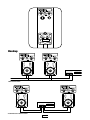
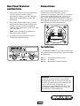
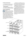
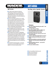
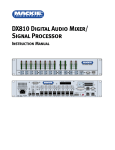
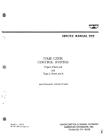
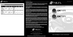
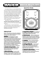
MONITOR MR3STK/SWTK
Compact Coaxial Speaker
Quick-Start Guide
The MR3STK (Black) and MR3SWTK (White)
are a compact two-way coaxial speaker system
featuring a built-in multi-tap constant voltage
transformer, with two detented rotary switches
for selecting wattage taps (constant voltage) or
4Ω (constant impedance) operation. The
4.75" carbon fiber woofer, in combination with
a coaxial 0.5" titanium metalized dome
tweeter, provide natural, smooth sound
reproduction, ideal for use in business music
systems and indoor/outdoor background
music applications.
The passive crossover is designed to reduce
heat dissipation and optimize the power
response of the loudspeaker. Connections are
made to recessed, color-coded spring-loaded
terminals.
The enclosure is constructed of highdensity polystyrene, with integrated mounting
points for use with the optional mounting
hardware, and includes a protective
perforated steel grille.
Safety First!
Before connecting and using the equipment,
please read this Quick-Start Guide carefully
and keep it for future reference.
WARNING
WARNING! This equipment has been
designed to be installed by qualified
professionals only! There are many factors to
be considered when installing professional
sound reinforcement systems, including
mechanical and electrical considerations, as
well as acoustic coverage and performance.
Mackie Industrial strongly recommends that
this equipment be installed only by a
professional sound installer or contractor.
1. Attention to the precautions – Always
follow the precautions provided on this
Mackie Industrial product and in the
instruction manual.
2. Water and humidity – Do not use this
Mackie Industrial product near water; for
example, in the vicinity of a bath tub or sink,
in a damp cellar, near a swimming pool, etc..
3. Foreign bodies and liquids – Be careful not
to allow any foreign bodies or liquids to get
into this Mackie Industrial product.
4. Technical service – The user should never
attempt to make any repairs on this Mackie
Industrial product unless otherwise indicated
in the instruction manual. All repairs should
be made by qualified service technicians.
5. Installation – Do not install this Mackie
Industrial product in any way that is not
provided for in the instruction manual.
6. Stacking multiple units – To prevent the
danger of falling equipment, never stack
multiple units of this Mackie Industrial
product unless this possibility is expressly
indicated in the instructions.
7. Respect the safety standards – The entire
sound system must be designed in
compliance with the current standards and
laws regarding electrical systems.
8. Specifications – When installing and using
this Mackie Industrial product, keep in mind
the technical specifications indicated in the
dedicated section of the manual.
below. According to the OSHA regulations,
any exposure over the maximum limits
indicated in the table can reduce the hearing
capacity of a person. To prevent potentially
dangerous exposure to high sound pressure
levels, anyone subjected to such levels must
use suitable protection. When a Mackie
Industrial product capable of producing high
sound levels is being used, it is therefore
necessary to wear ear plugs or protective
earphones when the limits shown in the table
are exceeded.
9. Accessories – Install and use this Mackie
Industrial product only with the accessories
specified by the manufacturer or supplied
with the product.
Hearing loss - Exposure to high sound levels
can cause permanent hearing loss. The sound
pressure level which leads to hearing loss
varies considerably from one person to
another, and depends on the duration of
exposure. The U.S. Government’s
Occupational Safety and Healt Administration
(OSHA) has established the maximum sound
pressure levels that can be with stood without
causing damage, which are shown in the table
Consult the specifications provided in the
instruction manual to know the maximum
sound pressure (SPL) the speaker is capable
of producing.
Duration per
day (hours)
Sound level
(dBA)
Typical example
8
90
Duo in a small club
6
92
4
95
3
97
2
100
1.5
102
1
105
0.5
110
0.25 or less
115
Subway train
Very loud classical music
Locomotive at 50 feet
Loudest parts at a rock concert
2
INPUT
Hookup
OUTPUTS
25V 50V 70V 100V GND
POWER AMPLIFIER
+
–
+
–
70V Connection
OUTPUTS
+
–
L
–
+
R
–
POWER AMPLIFIER
–
+
4 Ohm Stereo Connection
3
+
Connections
Rear Panel Features
and Controls
The spring-loaded speaker terminals are
designed to accept bare wire, up to a
maximum of 18 gauge. Strip 1/4” of insulation
off the end of the speaker wire, press in the
tab, and insert the bare wire into the hole.
When you release the tab, the wire is locked in
place. Make sure there are no stray strands of
wire outside the terminal connection.
1. This rotary control selects the power tap
for the internal constant voltage
transformer. Choices are 1W, 2.5W, 5W,
10W, 20W, and BYPASS (used for 4Ω
operation).
2. This rotary control selects the constant
voltage distributed system in which the
speaker is used. Choices are BYPASS
(used for 4Ω operation), 0(Off), 25V, 50V,
70V, and 100V.
–
+
Note: Use a slot-head screwdriver to
adjust the rotary controls.
3. Use these spring-loaded terminals to
connect the speaker wiring.
INPUT
Installation
The MONITOR MR3ST can be mounted using
the optional mounting brackets. These include
the following:
MA3-5
MA3-6
MA-7B
Articulated surface mount
U-bracket
Wall-mount support bracket
WARNING: Consult a professional rigger or
structural engineer prior to suspending
loudspeakers from a structure not intended
for that use. Always know the working load
limit of the structure supporting the
loudspeaker array. Always make sure that
the rigging hardware minimum rating is at
least five times the actual load.
4
MR3STK/MR3SWTK
Specifications
System:
Physical:
Freq. Range (–10 dB):
140Hz-21kHz
Enclosure:
45° back angles, high density
polystyrene
Freq. Response (–3 dB):
180Hz-19kHz
Attachment Inserts:
4 integrated threaded insert points
Horz. Coverage Angle (–6 dB):
110°, averaged 800Hz-16kHz
Color:
Vert. Coverage Angle (–6 dB):
110°, averaged 800Hz-16kHz
Matte black (MR3STK)
White (MR3SWT)
Grille:
Matching perforated steel grille
Directivity Factor Q (DI):
8.5 (9.3), averaged 800Hz-16kHz
Input Connectors:
Spring-loaded terminal
System Sensitivity 1:
89 dB, 1W@1m
Dimensions HxWxD:
8.27 in x 5.91 in x 5.31 in
(210 mm x 150 mm x 135 mm)
Rated Maximum SPL:
108 dB @ 1 m (3.3 ft) peak
Net Weight:
5.5 lb (2.5 kg)
Rated Nominal Impedance:
4Ω (bypassed)
Options:
System Input Power Rating 2:
35W IEC, 140W Peak
MA3-5 (MA3-5W):
Articulated surface mount
Black (White)
Recommended Amplifier 3:
250W RMS
MA3-6 (MA3-6W):
U-bracket
Black (White)
Constant Voltage:
25V, 50V, 70V, 100V
Power Taps:
MA-7B (MA-7W)
Wall-mount support bracket
Black (White)
1W, 2.5W, 5W, 10W, 20W
Crossover Frequency:
6.0kHz
Transducers:
Low Frequency:
4.75" (120 mm) carbon fiber woofer
High Frequency:
0.5" (13 mm) titanium metalized
dome tweeter, Ferrofluid cooled
1
Measured on-axis in the far field with 1 watt (2.00V RMS @
4Ω ) input and referenced to 1 meter distance using the
inverse square law. Listed sound pressure represents an
average from 300Hz to 3kHz.
2
IEC Spectrum, peak for 2 hours with +4.5 dB crest factor.
3
Recommended amplifier is a power capability value that
should be taken as a guide.
5
www.mackieindustrial.com
16220 Wood-Red Road NE, Woodinville, WA 98072 USA
TEL 888.337.7404, FAX 425.487.4337, [email protected]
UK +44.1268.571.212, FAX +44.1268.570.809 [email protected]
ITALY +39.0522.354.111, FAX +39.0522.926.208 [email protected]
FRANCE +33.3.8546.9160, FAX +33.3.8546.9161 [email protected]
GERMANY +49.2572.96042.0, FAX +49.2572.96042.10 [email protected]
Part No. 910-178-20 Rev. C1 2/02
© 2002 Mackie Industrial. All Rights Reserved.
6