1
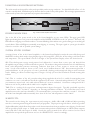
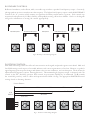
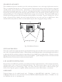
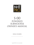
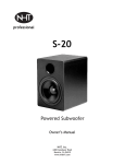
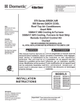
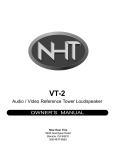
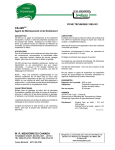
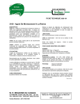
A-20
Owners Manual
A-20 Left Monitor Serial Number:
A-20 Right Monitor Serial Number:
A-20 Control Amplifier Serial Number:
Copyright 2001 NHTPro, a Recoton Corporation Brand
Safety Instructions -- Please Read First
CAUTION: To reduce the risk of electric shock, do not remove
the cover (or back). No user serviceable parts are inside; refer
servicing to qualified personnel.
WARNING: To reduce the risk of fire or electric shock, do
not expose this appliance to rain or moisture.
This symbol wherever it appears, alerts you to the presence
of uninsulated dangerous voltage inside the enclosure that
may be sufficient to constitute a risk of electric shock.
CAUTION
RISK OF ELECTRIC SHOCK
DO NOT OPEN
WARNING: SHOCK HAZARD-DO NOT OPEN.
AVIS: RISQUE DU CHOC ELECTRONIQUENE PAS OUVRIR.
This symbol, wherever it appears alerts you to
important operating and maintenance instructions in the
accompanying literature. Read the manual.
DETAILED SAFETY INSTRUCTIONS:
All the safety and operation instructions should be read before the appliance is operated.
Retain Instructions:
The safety and operating instructions should be retained for future reference.
Heed Warnings:
All warnings on the appliance and in the operating instructions should be adhered to.
Follow Instructions:
All operation and user instructions should be followed.
Water and Moisture:
The appliance should not be used near water (e.g. near a bathtub, washbowl, kitchen sink. laundry tub, in a wet basement, or near a swimming pool
etc.).
Ventilation:
The appliance should be situated so that its location or position does not interfere with its proper ventilation. For example, the appliance should not
be situated on a bed, sofa, rug, or similar surface that may block the ventilation openings, or placed in a built-in installation, such as a bookcase or
cabinet that may impede the flow of air through the ventilation openings.
Heat:
The appliance should be situated away from heat sources such as radiators, heat registers, stoves, or other appliances (including other amplifiers)
that produce heat.
Power Source:
The appliance should only be connected to a power supply of the type described in the operating instructions or as marked on the appliance.
Grounding and Polarization:
Precautions should be taken so that the grounding or the polarization means of the appliance is not defeated.
Power Cord Protection:
Power supply cords should be routed so that they are not likely to be walked on or pinched by items placed upon or against them, paying
particular attention to cords and plugs, convenience receptacles and the point where they exit from the appliance.
Cleaning:
The appliance should only be cleaned as recommended by the manufacturer.
Non-use Periods:
The power cord of the appliance should be unplugged from the outlet when left unused for a long period of time.
Object and Liquid Entry:
Care should be taken so that objects do not fall and liquids are not spilled into the enclosure through openings.
Damage Requiring Service:
The appliance should be serviced by qualified service personnel when;
The power supply cord or the plug has been damaged; or
Objects have fallen, or liquid has been spilled into the appliance; or
The appliance has been exposed to rain; or
The appliance does not appear to operate normally or exhibits a marked change in performance; or
The appliance has been dropped, or the enclosure damaged.
Servicing:
The user should not attempt to service the appliance beyond what is described in the Operating Instructions. All other servicing should be
referred to qualified service personnel.
INTRODUCTION:
Thank you for your selection of the A-20. Your studio monitors are a critical element in the countless decisions made
during recording, mixing, mastering and other key aspects of audio production. They must deliver a transparent, neutral
and revealing assessment of sound, so that you have the information you need to choose and place microphones, set
Eq’s, balance mixes... In other words, deliver exceptional product. The A-20 is capable of state of the art sonic
resolution and flexibility. Investing time to learn about the A-20’s features and operation will reward you with the
best possible performance.
If you require assistance at any time during or after the setup process, call our Customer Service Hot Line at (800)-NHT9993 (648-9993). You can also visit our web site at www.nhtpro.com for more in depth technical information. Thanks
again for your confidence in our products!
GETTING STARTED:
The A-20 is unique in that it combines a dedicated control amplifier with loudspeaker monitor cabinets, using controlled
impedance cables that actually form part of the crossover network. By designing the system as an integral package in
this manner, many of the advantages of self-powered speakers can be realized without attendant performance compromises.
However, it must be recognized that the control amp, cables and monitors are an inseparable package.
The A-20 must only be used with the A-20 Control Amp, cables, and vice versa.
The following are included in the Control Amplifier carton:
1 ea. - Control Amplifier
1 ea. - 6' IEC Power Cord
1 ea. - Warranty Registration Card
2 ea. - 20' Monitor Output Cables
4 ea. - 10-32 Rack Mounting Screws
8 ea. - Plastic Insulating Washers
Screws
The A-20 Control Amplifier may be used on a shelf, or mounted in a standard 19” equipment
rack using the screws and washers supplied. For rack mounting, remove and retain the four
feet from the bottom of the amp chassis using a #2 Philips screwdriver. Two vertical rack
spaces are required, but we recommend you leave at least one additional open space
above and below the A-20 for improved cooling, as you would with any high power amplifier.
For table or shelf use, the four feet must remain attached to allow for air circulation. As a
starting point for speaker placement, align the back of the enclosures parallel to the rear wall,
with the angled fronts facing in towards you. For more detailed speaker placement
information see page 7.
Monitor Output Cables
Signal flow
Signal flow
+11
+4
1
-3
M
-10
2
MF
0
POWER
FF
NF
100
MODE
SENSITIVITY
BOUNDARY
POSITION
SPL
TMP
PHONES
VAC
A-20
Control
Amplifier
To AC Line
Signal flow
Corel
Jpg
.
Fig. 2 Typical System Configuration
A-20
Amplifier
Front Panel
Insulating
Washers
Rack Rail
Fig. 1: Rack Mounting Detail
SYSTEM CONNECTIONS:
CAUTION: MAKE ALL CONNECTIONS WITH THE AC POWER OFF!
CAUTION:
CONNECTING THE OUTPUT OF THE A-20 CONTROL AMPLIFIER TO ANY
EQUIPMENT OTHER THAN THE A-20 OR C-20 MONITOR MAY CAUSE
EQUIPMENT DAMAGE.
CONTROL AMPLIFIER INPUT SECTION:
The A-20 Control Amplifier accepts both balanced and unbalanced inputs on either XLR or 1/4” TRS connectors. These
connectors are hardwired in parallel within the A-20 to allow for convenient equipment chaining, but only one signal source
should be physically connected to the unit at any time. Figure 3a shows the proper wiring schematic for each type of
connector. Since there are so many different connector types and signal levels employed by source equipment, some
experimentation may be necessary, keeping in mind that the A-20 can accept a wide range of signals and has an
input sensitivity control on the front panel.
2
PIN SIGNAL
3
1
2
1
3
XLR
1
GND
2
+
3
_
A-20 INPUT
SOURCE
+ (SIGNAL)
2
3
- (GND)
Shield
1
TRS
Fig. 3b Unbalanced Wiring Diagram
Fig. 3a Balanced Wiring Diagram
SPEAKER CABLE CONNECTIONS:
The A-20 includes two 20’ special purpose cables to connect the Control amplifier to the Monitors. While these cables look
similar to standard microphone cables, they are constructed with lower and more consistent conductor impedance. Portions
of the A-20’s crossover circuitry are located in both the amplifier and speaker enclosures, and the cables supplied are an
important part of this electrical network. This allows the speaker cables to function as a neutral and transparent component
in the system. Replacing or extending the supplied cables with any other type will have a varying, and only partly predictable
impact on the sound of the A-20. If your installation requires the use of alternative cables, you may consult the table listing our
measurement data on a variety of cable types at www.vergenceaudio.com under the support section. Be sure they are wired as
shown in Fig. 3a. These considerations aside, using the Vergence cables to connect the control amplifier is quite simple and
straight forward. Both the amplifier and the monitors are marked with the appropriate “left” and “right” channels. Fit the
XLR connectors into the corresponding connectors on the control amplifier and monitors until the connector locks.
WARNING: IF USING CABLES OTHER THAN THOSE SUPPLIED WITH THIS SYSTEM, BE SURE
THAT NO CONDUCTIOR IS WIRED TO THE XLR CASING. FAILURE TO
DO SO
MAY CONSTIT UTE A RISK OF ELECTRIC SHOCK.
A-20 Monitor
Right
CAUTION
RIGHT
RISK OF ELECTRIC SHOCK
DO NOT OPEN
LEFT
WARNING: SHOCK HAZARD-DO NOT OPEN.
AVIS: RISQUE DU CHOC ELECTRONIQUENE PAS OUVRIR.
FUSE TYPE:
T9A 250V FOR 110/120V.
T5A 250V FOR 220/240V.
50/60 Hz - 950W
2
3
1
2
UL
LISTED
AUDIO EQUIP
1
3
XLR
A20-A-10001
NHTPro
BENICIA, CALIFORNIA, U.S.A.
MADE IN TAIWAN G1
INPUT
FOR CONTINUED PROTECTION AGAINST
RISK OF FIRE REPLACE ONLY WITH SAME
TYPE 250V FUSE.
INPUT VOLTAGE
MODEL A-20 CONTROL AMPLIFIER.
SERIAL NO:
CAUTION:
A-20 Monitor
Left
NHTPro
PIN SIGNAL
1
GND
2
+
3
_
TRS
Fig. 4 A-20 Control Amplifier Rear Panel
CAUTION:
CONNECTING OUTPUTS TO ANY
PRODUCT OTHER THAN A-20 or
C-20 MONITORS MAY RESULT IN
SEVERE EQUIPMENT DAMAGE.
USING THE A-20 CONTROL FUNCTIONS:
The A-20 controls are designed for utility and repeatability under varying conditions. You should find the effects of the
controls sonically subtle, with little impact on the basic character and accuracy of the speaker. We encourage experimentation
to fine tune the system to the requirements of your particular installation.
+11
+4
1
-3
M
-10
2
MF
0
POWER
FF
NF
100
MODE
SENSITIVITY
BOUNDARY
POSITION
SPL
VAC
PHONES
TMP
A-20
Control
Amplifier
Fig. 5 A-20 Control Amplifier Front Panel
POWER INDICATORS:
Just to the left of the power switch on the A-20 Control Amplifier are two status LED's. The upper (green) LED
lights up indicating there is AC power to the amplifier and the POWER SWITCH is in the “on”position. The lower (red)
LED indicates a clipping or overload condition. Occasional flashing of this indicator is a gentle warning you are reaching the
system’s limits. If the red LED glows continually, severe clipping is occurring. The input signal or system gain should be
reduced to avoid the risk of possible system damage.
SYSTEM STATUS DISPLAY:
A unique feature of the A-20 Control Amplifier is the System Status Display located in the center of the front panel.
Small LED’s indicate which mode is being displayed; green for average SPL, yellow for AC line voltage, and blue for heat
sink temperature. The square “Mode” switch to the right of the System Status Display selects the desired mode.
SPL: This is the long term average sound pressure level calibrated at 2 meters from a stereo pair, and derived from
the amplifier output voltage. Peak sound levels are ignored. The readout is designed to inform the user of overall listening
levels, and to help realize consistent monitoring conditions from hour to hour, session to session and room to
room. Levels under 68 dB are shown as “00”; levels over 120 dB are shown as “HI”. Since monitoring level has a
profound influence on the perception of sonics, periodically checking your listening levels helps to assure consistent
results. Making an effort to combat long term ear fatigue can help you avoid the heartbreak of harsh morning after
realities.
VAC: This is a readout of the AC power line voltage being supplied to the A-20. It is useful for assuring that power
conditions are correct and sufficient for all the equipment on the circuit. Sustained readings below 110 V may limit
your maximum output levels, and could indicate that the AC circuit is overloaded. Continuous readings above 125 V
indicate an AC circuit problem, which could lead to amplifier failure.
TMP: This is a reading of the output heat sink temperature in degrees Centigrade. Typically, you should expect this
to run between 50°C and 80°C, depending on listening and ambient conditions. If you find that your Control
Amplifier unit tends to run hotter than 80°C, it is recommended that you improve the ventilation around it. Note that
the A-20 Control Amplifier will automatically shut down if the heat sink temperature reaches 100°C.
SENSITIVITY:
This control is used to change the input sensitivity with settings at; -10dB, -3dB, +4dB, +11dB and (M)ute providing
noise free, consistent gain matching with a wide variety of equipment. The proper setting is the lowest sensitivity possible
(highest dB number) which allows the speaker to reach the maximum desired output without source clipping. Professional
devices typically spec full output at +4dB, most consumer audio products reach full output at -3dB, and most computer
sound cards have a full scale output of -10dB. Consult the owner’s manual for the device connected to the Control
Amplifier for its output level specifications and set the SENSITIVITY control accordingly.
BOUNDARY CONTROL:
Reflective boundaries, such as floors, walls, even table tops, reinforce a speaker’s low frequency output. Conversely,
placing speakers out into a room decreases bass response. The highest low frequency output is with the BOUNDARY
control in the “0” position, which assumes no significant boundary reinforcement is present. Each control step
attenuates low frequencies by 1.5 dB (at 50 Hz), with rapidly decreasing effect above 300 Hz. Refer to the diagram
in Fig. 6 for information on setting the control appropriately.
Quarter/Half Space
Quarter Space
2
0
2
0
BOUNDARY
BOUNDARY
Half/Whole Space
1
1
1
2
Half Space
Whole Space
1
1
0
2
BOUNDARY
2
0
0
BOUNDARY
BOUNDARY
Fig. 6. Boundary Control Settings Diagram
POSITION CONTROL:
Near-field monitoring reduces the effect of room acoustics on the signal, and provides greater sonic detail. Mid- and
far-field listening reveals aspects of recorded ambience and is more representative of end use. However, a speaker’s
upper frequency power response changes with distance, due to room influences and air absorption. The A-20 may be
adjusted for flat response at various listening distances. The maximum high frequency output is obtained with the
control in the “FF” (far-field) position. Each control step attenuates 20 kHz by an additional .75 dB (towards
the near-field position) with no effect on frequencies below 3 kHz. See Fig. 7 for appropriate POSITION control
settings based on listening distances.
Listener Distance
0’
1.5M
1M
3M
2.5M
2M
Far-Field
A-20
Monitor
Mid-field
Near-field
MF
MF
FF
NF
POSITION
POSITION
MF
MF
FF
NF
FF
NF
POSITION
Fig. 7. Position Control Settings Diagram
MF
FF
NF
POSITION
FF
NF
POSITION
SPEAKER PLACEMENT:
The A-20 Monitor System is intended to provide consistent performance over a wide range of placement situations.
This is accomplished through the use of electrical controls, wide dispersion drivers, advanced enclosure design and
carefully chosen crossover characteristics. Nevertheless, it is always worth investing time and effort experimenting
with optimum loudspeaker placement. In all cases, A-20 Monitors should be set up symmetrically equidistant from
the listening position; the left speaker and right speaker should be at the same relative positions with respect to the
primary listening area. This is important in order the hear a proper stereo sound stage. The speaker baffles angle in
towards the listening position with the loudspeaker backs parallel to one another. A good starting point can be
found in Figure 8 below. Ideally, the tweeter height should be on axis with your ears, or slightly above. Also,
remember that nearby reflective surfaces can alter impulse response, blur imaging and change tonality.
D x 1.5
D
Listening Position
Fig. 8 Ideal Monitor Placement
SYSTEM OPERATION:
The A-20 is capable of very high output levels, especially when listening in the near-field. Protect your ears and use common
sense. Still, every speaker system has its limits. Harsh breakup at extremely high volume, or heat emanating from the drivers is
an indication that the system has exceeded its output limits and you should lower the playback level. Watch for excessive
lighting of the front panel overload indicator on the Control Amplifier. Speaker damage most often occurs from sustained
high volume levels, not from transient sounds or brief musical peaks.
A-20 MONITOR SYSTEM CARE:
Except for the occasional flattering comment, your A-20 System needs no regular maintenance. Never attempt to clean the A20 monitor driver units except for very light feather dusting. The A-20 monitor cabinets and the A-20 Control
Amplifier front panel can be cleaned using a damp, soft cotton cloth first sprayed with a mild, non-abrasive glass
cleaner. Never spray the speaker or amplifier directly! Avoid silicone and oil based cleaners or treatments.
NEED HELP?
Technical Support can be reached several ways: Telephone us (800)-NHT-9993 (648-9993), E-mail us at:
[email protected], Fax us at: (707) 747-1252 or write us at: NHTPro, 6400 Goodyear Rd., Benicia, CA 94510. Or visit
our world wide web site at www.nhtpro.com.
SYSTEM SPECIFICATIONS:
Type: Modular, two- piece powered near/mid/far field monitor.
Configuration: 2-way acoustic suspension.
Woofer: 6.5" curvilinear treated paper. Butyl surround.
Tweeter: 1" metal dome, textile surround, ferrofluid cooled and damped.
Magnetic Shielding: Partial, 12-18” working distance from PC monitor recommended.
PERFORMANCE SPECIFICATIONS:
Amplifier Power: 250W (continuous RMS/ch), 400W (100ms peak).
Peak Acoustic Output: 117 dB SPL (100ms pink noise @ 1M).
Residual hum/noise: <10 dB SPL @ 1M.
System THD @ 90 dB SPL: <0.4% (100Hz ~ 10kHz @ 1M).
Response: +/- 2 dB (1/3 oct. swept noise): 48Hz ~ 20kHz@ 1M, 45Hz ~ 20kHz @ 2M.
-6dB LF cutoff: 40Hz (in-room response).
Loudspeaker Dimensions/Wgt.: 14" h x 7.5" w x 11.9" d, 19 lbs.
Loudspeaker Materials: 0.75" MDF w/high pressure laminate (internal + external).
Control Amplifier Dimensions/Wgt.: 3.5" h x 19" w x 13.375" d/37 lbs.
FEATURES/CONTROLS:
Connectors:
Input: XLR, TRS.
Output to monitor: XLR.
Controls:
Sensitivity: 5 position (-10dB,- 3dB, +4dB, +11dB, Mute).
Boundary: 5 position (0.0, 0.5, 1.0, 1.5, 2.0 representing walls).
Position : 5 position, near(1M), near-mid(1.5M), mid(2M), mid-far(2.5M), far (3M~).
Power: On, off.
Display Mode
Display:
C).
Switchable: SPL Output (68dB ~ 120dB), Line Voltage(90 ~ 135VAC), Heat Sink Temp.(20 - 99
LED’s:
Power, Overload.
Other:
Headphone Output (insertion interrupts main output).
NHTPro
6400 Goodyear Rd.
Benicia, CA 94510
ph: (707)748-5940
fx: (707)747-1252
www.nhtpro.com
o