1
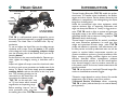
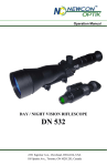
This Product made by:
Newcon Optik
105 Sparks Ave
Toronto, Ontario,
M2H 2S5 Canada
Tel: 1 416 663 6963
Fax: 1 416 663 9065
www.newcon-optik.com
E-mail: [email protected]
Export Information. Night Vision and Thermal Imaging Equipment in general is subject
to export control. Please consult your Local and Federal Government Authorities prior to
purchase or further shipment of the Controlled Goods. Newcon Optik relieves itself from
any liabilities, claims or accusations if its equipment is found in certain destinations without
proper Export Documentation. Newcon Optik under NO circumstance will illegally export
Basic User’s Manual
THERMAL IMAGING
BINOCULARSGOGGLES
TVS 7B
©2010 NEWCON OPTIK
Manufacturer’s Warranty
2
7
Newcon Optik warrants it’s Optical Products against genuine
Dear Customer.
This Manual is a basic instruction on operating
the Thermal Imaging Device TVS 7B. We assume that
an operator has a knowledge in principle on use of
electro-optical systems. However if you find any
difficulties in operating device please:
1. Read this Manual thoroughly to make sure that you
understand completely its instructions and warnings.
2. Contact our Technical Support Service via phone, fax,
e-mail.
We hope that you will enjoy our Products. Thank you.
NEWCON OPTIK
manufacturer’s defects in materials and workmanship for a period of
one full year from the original date of purchase. All optical electronic parts,
components which used in covered products, such as image intensifier tubes,
focal plain arrays (thermal cores) are covered by their original Manufacturer’s warranty. Any device returned for warranty service or repair must be
judged by Newcon’s Technical Control Department as having been used
accordingly its original design intents. As such misuse, neglect, or any
abnormal use is not covered by this warranty. Product’s malfunction or
deterioration due to normal use is not covered by this warranty. NEWCON
will repair or replace such products or parts which, upon inspection by TCD
is found to be defective in either materials or workmanship. As a condition of
NEWCON obligation regarding a warranty work, the product must be
returned to the place where it has been purchased with satisfactory proof of
purchase (sales invoice must be presented). This warranty is null and void if
Specifications of TVS 7B
Sensor
Type*
Detector
Display(s) Resolution
Output Resolution
Thermal Sensitivity
Spectral Response
Focal Length
Field of View
Lens type
Video Output
Water Resistant
Power Supply
Battery size
Weight
Microbolometer*
“TI-3620as”, Uncooled
Amprhpous Silicon
640 x 480
640 x 480
<100 mk
7-14 um
25 mm
11 x 8 degrees
Germanium
NTSC
Yes
2.5-3.3V
Lithium/rechargeable AA
450 gr
equipment has been altered, tampered with, modified, or otherwise abused,
mishandled or subjected to unauthorised repairs. NEWCON disclaims any
other warranties, either expressed or implied, except as expressed herein. The
sole obligation of NEWCON is to repair or replace the covered device. NEWCON expressly disclaims responsibility for any lost profits, general, specific,
direct, undirect, or consequential damages which may result from breach of
any warranty, or resulting from the use, or inability to use any NEWCON’s
product. Do not return merchandise directly to NEWCON without expressed
permission of our Customer Service Representative who has to issue a Return
Authorisation Number (RA#). NEWCON accepts No responsibility for
unauthorised returns. All items returned for exchange, upgrade, repair,
service etc. must be with all accessories, in original packaging, shipping and
insurance cost prepaid both ways. Items received by NEWCON without RA#,
missing parts or accessories, or damaged due to inadequate packaging, or
customer’s abuse (i.e. scratched, cracked body, burned IIT/FPA or broken
lens)-will be returned back to customer or repaired for the cost.
FPA Ser. No: ______________________Housing Ser. No:________________________
Head Gear
6
ROTATION ENABLING
BUTTON
BUTTON
RING
MOUNTING
ADAPTER
SLEDGE
TVS 7B ATTACHED
TO HELMET MOUNT
TVS 7B is a self-contained system designed for use as
binoculars (hand-held operation) or goggles (head/Helmet
mounted). The Head Gear is furnished with “flip up”
mechanism.
To set and adjust the Head Gear turn the ring counter
clockwise until it stops. Press the button in the middle
of this ring and insert the mounting adapter sledge
into the mounting slot of the Device. Now you can release the button.
Set the Device in the most comfortable for Operator position, tighten the ring by turning it clockwise until it
stops.
Adjust and tighten all straps around the head and under
the chin to reach more convenient and stable state of the
device. To “flip-up” the Device simply press the rotation
enabling button and turn the device to the “top” position. The mounting bracket can be
removed from the Head Gear and
mounted to the helmet as well.
TVS 7B can be used with “snap
on” 50 mm lenses which increases
magnification and operating range.
Before attaching “snap on” lens remove protective cover ring from
the existing lens of the TVS 7B.
Introduction
3
Thermal Imaging Binoculars TVS 7B enable the professional users to visualize a heat irradiated by live bodies,
targets and other objects. Device detects extremely low
difference in temperature, thus distinguishing the object
image from its background.
Unlike the conventional night vision equipment, which
requires minimum light or supporting illumination and
might not always be effective in smoky or foggy environment, TVS 7B needs no light to operate and generates
high-quality image in the harsh weather conditions. The
camouflage doesn’t help to obscure a hiding body as TVS
7B detects body’s heat through.
Thermal imager is powerful tool for tactical, surveillance
and scene assessment applications. Its small size, light
weight and convenient bi-ocular design make TVS 7B
simple and effective in operation. Law enforcement, public safety service and other professional users can use the
system to conduct hidden compartment searches, perimeter surveillance, marine or ground surveillance, safer
flights, structure profiling activities, fugitive and rescue
searches, disturbed surface investigations, pollutant
searches and vehicle pursuits. In fire and rescue applications, thermal imaging is used to conduct scene size up,
in-fire attack, search and rescue, hazmat assessments and
post-fire overhaul.
TVS 7B can be used as hand-held Thermal Imager Binoculars or head/helmet-mounted Goggles.
*Detection range depends on various factors, like outside
temperature, size of object, type of lens used etc.
**Universal Service Connector allows connecting
TVS 7B to video (cable enclosed) or to external battery
pack (optional)
Description
4
9
2
How To Do It
9
4
1
3
8
6
7
5
1. ON/OFF Power Button Switch
2. Left & Right Eyepieces with Rubber eyecups*
3. Manual Brightness Control (override) of displays.
4. Digital Zoom Button Switch
5. Universal Service Connector (see details on page 4)
6. Front lens with Focusing Ring
7. “Black hot-white hot” Button Switch (“BH-WH”)
8. Battery Compartment Cover
9. Dioptric Adjustment Rings.
*Interpupillary adjustments between eyes. Slide<-> or >-<
External Power Pack.
Very convenient for long time or cold weather operation.
Comes with high capacity Li-Ion batteries and universal
charger. Good for up to 8 hours of continuous work.
Caution! When external battery pack is in use strictly
recommended to remove 2 pcs. of AA batteries from
battery compartment. Leaving them inside will cause
overheating of the device and/or batteries which would
cause batteries leakage and power drain from the external battery pack. Battery Pack has red LED which is ON
when connected to TVS 7B. Universal 110-250 V
charger is included.
IMPORTANT NOTICE. USE OF IMPROPER
BATTERIES OR VOLTAGE MAY SERIOUSLY
DAMAGE DEVICE WITH NO WARRANTY
COVERAGE FROM US!
5
This is the short description how to operate TVS 7B.
Read carefully to make sure you fully understand how to
power up your Thermal Imager properly.
TVS 7B needs minimum 2.4 V and Maximum 3.3
V, therefore Use only Lithium type 2 pcs. AA batteries
(1.5V each) or at least 2500 mAh Rechargeable batteries
AA size (1.2V each).
To begin with, install batteries into battery compartment
(8) complying with polarity guidance (-)inside, (+)outside.
Remove cover from the front lens and switch Power Button into position ON. Clicking sound in the beginning of
usage is normal for thermal core. By turning and moving
Dioptric Adjustment rings (9) adjust diopters and distance between eyepieces to satisfy the user eyes’ visual
acuity for the system’s best performance. Observing the
object adjust focus by turning front lens (6).
With optional Video-Out-to USB adapter and software the video signal from Thermal Imager can be transferred to the computer and stored for tactical purposes.
Video-Out cable.
Allows to connect TVS 7B to any standard RCA VideoIn (monitor, TV, VCR etc.)
Video-Out-to USB adapter and software.
Allow to transfer images into digital format for further
transfer to a computerized fire control system.
NOTE. All technical description and features of the product are subject to
change without prior notice.
A
TTENTION!
DO NOT POINT THE TURNED ON DEVICE
TO THE BRIGHT LIGHT SOURCE! IN SOME CASES LIGHT
OVERLOAD MAY CAUSE IRREVERSIBLE REDUCTION OF I.I.T. OR
F.P.A. RESPONSIVITY OR PERMANENT DAMAGING.