1
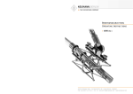
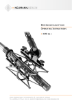
neumann.berlin
the microphone company
Bedienungsanleitung
Operating Instructions
KMR 82 i
georg neumann gmbh · ollenhauerstr. 98 · 13403 berlin · germany
fon +49 (0)30 / 41 77 24-0 · fax -50 · [email protected] · www.neumann.com
KMR 82 i
Inhaltsverzeichnis
Table of Contents
1
Das Kondensator-Richtrohrmikrophon KMR 82 i
1.
The KMR 82 i Condenser Shotgun Microphone
1.1
Ausführungsformen und Beschaltung des
Mikrophonausganges
1.1
Microphone Versions and Output Wiring
1.2
Mikrophonkabel
1.2
Microphone Cables
2.
Stromversorgung
2.
Power Supply
2.1
Phantomspeisung
2.1
Phantom Powering
2.2
Betrieb mit Netzgeräten
2.2
Operation with AC Power Supply
2.3
Batteriespeisung
2.3
Battery Powering
2.4. Betrieb an unsymmetrischen und
mittengeerdeten Eingängen
2.4. Operation with Unbalanced or
Center Tap Grounded Inputs
3.
Technische Daten
3.
Technical Specifications
4.
Frequenzgänge und Polardiagramm
4.
Frequency Responses and Polar Pattern
5.
Empfehlungen für den Gebrauch der Windschutzeinrichtungen
5.
Recommendation for the Use of Windscreens in
Combination
6.
Einige Hinweise zur Pflege von Mikrophonen
6.
Hints on Microphone Maintenance
7.
Zubehör
7.
Accessories
1.
Das KondensatorRichtrohrmikrophon KMR 82 i
1.
The KMR 82 i Condenser
Shotgun Microphone
Das Richtrohrmikrophon KMR 82 i ist ein Kondensatormikrophon der Serie fet 80®. Es wird vorzugsweise eingesetzt, wenn das Aufnahmemikrophon
nicht nahe an der Schallquelle postiert werden
kann oder wenn es bei Videoaufnahmen nicht im
Bild erscheinen darf. Die Richtcharakteristik des
Mikrophons ist keulenförmig.
Das Mikrophon KMR 82 i zeichnet sich durch nahezu frequenzunabhängige Dämpfung seitlich
einfallenden Schalls, geringstes Eigenrauschen
und gutes Impulsverhalten aus. Kleine Abmessungen und geringes Gewicht bei günstig liegendem
Schwerpunkt ermöglichen ermüdungsfreie Handhabung und problemlose Schwenks ohne Nachwippen des Mikrophons.
Aus der Forderung nach möglichst gleichmäßiger
Dämpfung bei allen Frequenzen des Übertragungsbereichs ergibt sich eine vergleichsweise
geringe Länge des verwendeten Richtrohres. Für
Frequenzen, deren Wellenlänge größer als die
Rohrlänge ist, arbeitet das Mikrophon als Druckgradientenempfänger, während es oberhalb
1,5 kHz für seitlich einfallenden Schall als Inter-
2
The KMR 82 i shotgun microphone is a fet 80®
series condenser microphone. lt is particularly recommended for use under recording conditions
where a conventional microphone cannot be positioned within the desired distance of the sound
source or, for video, when the microphone should
not appear in the picture. The directional characteristic of the KMR 82 i is lobe shaped.
The KMR 82 i microphone is characterized by its
largely frequency-independent rejection of sound
impinging at any angle off the microphone’s maximum sensitivity axis, by its very low self-noise
and its good transient behavior. Its small dimensions and lightweight construction with a convenient centre of gravity, make for ease of handling
and unproblematic panning without any whiplash
effect.
Since it is desirable that all frequencies be attenuated to the same extent, the interference tube
may be kept relatively short. At frequencies
whose wavelength is longer than the tube length,
the microphone works as a pressure gradient
transducer, whereas for laterally-incident sound
ferenzempfänger wirkt. Schallereignisse außerhalb der „Blickrichtung“ des Mikrophons werden
zwar leiser, aber nicht klangverfärbt aufgenommen. Das Mikrophon kann daher auch zur gezielten Aufnahme einzelner Instrumente im Orchester
eingesetzt werden. Auch die Überlappung der Aufnahmebereiche mehrerer Richtrohre ist problemlos möglich.
Das KMR 82 i ist sehr hoch aussteuerbar und besitzt eine bemerkenswert niedrige Ersatzlautstärke. Der Strombedarf von 0,7 mA, das geringe Gewicht von 250 g und die Unempfindlichkeit gegenüber Wind- und Griffgeräuschen machen das
Mikrophon auch für den Reportagebetrieb
besonders geeignet. Bei Außenaufnahmen ist dennoch ein zusätzlicher Schutz gegen Windeinflüsse empfehlenswert. Der Windschirm WS 82 aus
Polyurethanschaum gehört zum Lieferumfang und
sorgt auch während des Transportes für weiche
Lagerung des Mikrophons in seinem Lederköcher.
above 1.5 kHz, it operates according to the phasecancellation principle. As a result, sound from off
the microphone’s maximum sensitivity axis is
picked up with reduced intensity, but without
sound coloration. The KMR 82 i may therefore
also be used to record individual instruments of an
orchestra. The overlapping of the pick-up areas of
several interference tubes likewise presents no
problem.
The KMR 82 i is virtually overload-proof and has
a remarkably low self-noise level. Its 0.7 mA current consumption, its 250 g light weight and its
insensitivity to wind and finger noise make it also
ideally suited for location reporting. However, for
outdoor use an additional wind protection is
recommended. For this purpose a WS 82 expanded polyurethane windscreen is included. The
windscreen doubles as soft padding when the microphone is in its leather carrying case.
Als weitere Maßnahme gegen Störschall beschneidet im KMR 82 i ein elektrischer Hochpass
unterhörfrequenten Schall. Seine Grenzfrequenz
lässt sich mit einem versenkt angebrachten Schiebeschalter auf 120 Hz (–3 dB) erhöhen.
As a further measure, an electrical high-pass filter cuts off subaudible frequencies. Its turn-over
frequency may be raised to 120 Hz (–3 dB) by
means of a flush-mounted slide switch.
Im Frequenzbereich von 2 kHz bis 15 kHz besitzt
das Übertragungsmaß des KMR 82 i eine Anhebung zum Ausgleich von Übertragungsverlusten in
Luft bei großen Entfernungen des Mikrophons zur
Schallquelle.
The KMR 82 i now shows a boost in the frequency range between 2 kHz and 15 kHz, to compensate for air friction losses for larger sound source
to microphone distances.
Bei Nahaufnahmen können dadurch insbesondere
Zischlaute überbetont werden. Deshalb erlaubt
ein zweiter Schiebeschalter, das Übertragungsmaß
für hohe Frequenzen relativ abzusenken (10 kHz
– 4 dB) und damit zu linearisieren (s. Seite 12).
This may produce over accentuation of sibilant
sounds for close microphone placement. A second
slide switch has therefore been added to lower
those higher frequencies (10 kHz – 4 dB), thereby
linearizing the response.
1.1 Ausführungsformen und Beschaltung
des Mikrophonausganges
1.1 Microphone Versions and
Output Wiring
Das Mikrophon kann in folgenden Ausführungsformen geliefert werden:
The following versions of the KMR 81 i microphone are available:
KMR 82 i ............ ni ............. Best.-Nr. 06878
Ausführung mit 3-poligem Switchcraft-Steckereinsatz und nickelmatter Oberfläche. Erforderliches
Gegenstück: XLR 3 F.
KMR 82 i ............ ni ............... Cat. No. 06878
Version with male 3-pin connector insert and satin nickel finish. Requires XLR 3 F female connector.
KMR 82 i mt ....... sw ............ Best.-Nr. 06879
wie oben, jedoch mit schwarzmatter Oberfläche.
KMR 82 i mt ....... blk ............. Cat. No. 06879
as above, but with matte black finish.
Die Zuordnung der Mikrophonanschlüsse entspricht DIN EN 60268-12 bzw. IEC 60268-12:
The microphone is wired as per DIN EN 60268-12
or IEC 60268-12.
3
KMR 82 i
Die Modulationsadern liegen an Pin 2 und 3, die
Abschirmung an Pin 1. Bei einem Schalldruckanstieg vor der Mikrophonmembran tritt an Pin 2 eine
positive Spannung auf.
The modulation is connected to pins 2 and 3; the
shield is connected to pin 1. A sudden increase in
sound pressure in front of the microphone diaphragm causes a positive voltage to appear at pin 2.
Der 3-polige XLR-Steckverbinder hat folgende
Belegung:
The 3-pin XLR connector has the following pin assignments:
Pin 1: 0 V/Masse
Pin 2: Modulation (+Phase)
Pin 3: Modulation (–Phase).
Pin 1: 0 V/ground
Pin 2: Modulation (+phase),
Pin 3: Modulation (–phase).
Auf die Anschlussdosen können wahlweise auch
dynamische Mikrophone oder Bändchenmikrophone sowie die Modulationskabel röhrenbestückter
Kondensatormikrophone geschaltet werden, ohne
dass die Speisegleichspannung abgeschaltet werden muss.
Der Ausgang eines Neumann-Phantomspeisegerätes darf auch auf bereits anderweitig phantomgespeiste Mikrophoneingänge gesteckt werden.
2.2 Betrieb mit Netzgeräten
1.2 Mikrophonkabel
2.
Für das KMR 81 i stehen folgende Kabel zur Verfügung:
The following cables are available for the KMR 81 i
microphone:
IC 3 mt ............... sw ............ Best.-Nr. 06543
Mikrophonkabel mit Doppeldrallumspinnung als
Abschirmung. Ø 5 mm, Länge 10 m. XLR 3 Steckverbinder, schwarzmatt.
IC 3 mt ................ blk ............. Cat. No. 06543
Microphone cable with double twist (double helix) braiding as shield. Ø 5 mm, length 10 m.
XLR 3 connectors, matte black.
IC 31 mt (5 m) ... sw ............ Best.-Nr. 06570
Mikrophonkabel mit Doppeldrallumspinnung als
Abschirmung. Textilumsponnen, zur Vermeidung
von Reibgeräuschen bei der Verwendung an Mikrophonangel oder Windschutzkorb. Ø 4,5 mm,
Länge 5 m. XLR 3 Steckverbinder, schwarzmatt.
IC 31 mt (5 m) .... blk ............. Cat. No. 06570
Microphone cable with double twist (double helix)
braiding as shield. Textile-braided to avoid frictional noise due to the handling of booms or plastic
leadings (for example in windscreens). Ø 4,5 mm,
length 5 m. XLR 3 connectors, matte black.
AC 25 (0,3 m) ...................... Best.-Nr. 06600
Adapterkabel mit XLR 3 F-Buchse und 6,3 mm Monoklinkenstecker, unsymmetrisch, für den Anschluss des 3-poligen XLR-Ausganges eines Speisegerätes an Geräte mit 6,3 mm Monoklinkenbuchse. Für alle Mikrophone mit Ausnahme der
Ausgangsstufe KM 100 und des GFM 132.
AC 25 (0.3 m) ......................... Cat. No. 06600
Adapter cable with XLR 3 M connector and unbalanced 6.3 mm mono jack. It is used to connect 3pin XLR outputs of power supplies to units with a
6.3 mm monojack input. Designed for all microphones, excluding KM 100 System and GFM 132.
Andere Kabellängen sind auf Wunsch lieferbar.
Special cable lengths can be made to order.
Stromversorgung
2.1 Phantomspeisung
Das KMR 82 i wird mit 48 V phantomgespeist (P48,
IEC 61938).
Bei der Phantomspeisung fließt der Speisestrom
vom positiven Pol der Spannungsquelle über die
elektrische Mitte der beiden Modulationsadern
zum Mikrophon. Er wird hierzu über zwei gleichgroße Widerstände beiden Tonadern gleichsinnig
zugeführt. Die Rückleitung des Gleichstroms erfolgt über den Kabelschirm. Zwischen beiden Modulationsadern besteht also keine Potentialdifferenz. Daher ist mit der Phantomspeisung eine kompatible Anschlusstechnik möglich:
4
1.2 Microphone Cables
2.
Power Supply
2.1 Phantom Powering
The KMR 82 i is phantom powered at 48 V (P48,
IEC 61938).
With phantom powering the dc from the positive
supply terminal is divided via two identical resistors, one half of the dc flowing through each audio (modulation) conductor to the microphone, and
returning to the voltage source via the cable
shield. Phantom powering provides a fully compatible connecting system, since no potential differences exist between the two audio conductors.
Für die Stromversorgung sind alle P48-Netzgeräte geeignet, die mindestens 1 mA je Kanal abgeben.
Das Neumann P48-Netzgerät hat die Bezeichnung
N 248. Es ist zur Stromversorgung zweier MonoKondensatormikrophone oder eines Stereomikrophons mit 48 V ± 1 V, maximal 2 x 6 mA, geeignet
(siehe auch Neumann-Druckschrift 68832: „48 VPhantomspeisegeräte“).
Die Zuordnung der Mikrophonanschlüsse und die
Polarität der Modulationsadern ist am Ausgang
des Speisegerätes die gleiche wie am Mikrophon.
Das Netzgerät N 248 versorgt ein oder zwei Mikrophone mit 48 V-Phantomspeisung P48. Alle Anschlüsse mit XLR 3-Flanschdosen. Die Modulationsausgänge sind gleichspannungsfrei.
Studio outlets so powered will therefore also accept dynamic microphones and ribbon microphones as well as the modulation conductors of
tube-equipped condenser microphones without the
need to switch off the dc supply voltage.
No harm is done even if a Neumann phantom power supply is connected to the inputs of microphones which are phantom powered from another
source.
2.2 ac Supply Operation
All P48 power supplies in accordance with
IEC 61938 which provide at least 1 mA per
channel, are suitable for powering the microphones.
The Neumann P48 power supply unit bears the
designation N 248. It is designed to power two
mono condenser microphones or one stereo microphone at 48 V ± 1 V, max. 2 x 6 mA (see also Neumann bulletin no. 68832: “Phantom 48 VDC Power Supplies”).
The assignment of the microphone terminals and
the modulation polarity at the power supply output are identical to those at the microphone.
The N 248 supplies one stereo microphone, or two
mono condenser microphones with 48 V phantom
power (P48). All connectors are of XLR 3 type. The
audio signal outputs are DC-free.
Das Gerät ist in drei Ausführungen erhältlich:
Three versions are available:
N 248 EU ............ sw ............ Best.-Nr. 08537
N 248 US ............ sw ............ Best.-Nr. 08538
N 248 UK ............ sw ............ Best.-Nr. 08539
N 248 EU ............ blk ............. Cat. No. 08537
N 248 US ............ blk ............. Cat. No. 08538
N 248 UK ............ blk ............. Cat. No. 08539
2.3 Batteriespeisung
2.3 Battery Powering
Steht keine Netzspannung zur Verfügung, kann die
Speisung mit einem der Geräte
If a mains power source is not available, power
can be supplied by one of the battery units
BS 48 i .................................. Best.-Nr. 06494
(für ein Mikrophon)
BS 48 i .................................... Cat. No. 06494
(for one microphone)
BS 48 i-2 ............................... Best.-Nr. 06496
(für zwei Mikrophone)
erfolgen. Beide Geräte liefern 48 V ± 1 V, maximal
je 5 mA, und werden jeweils von einer 9 VoltBlockbatterie Typ IEC 6 F 22 gespeist.
BS 48 i-2 ................................. Cat. No. 06496
(for two microphones)
Both units deliver 48 V ± 1 V, at 5 mA maximum,
and are powered by a 9-volt monobloc battery
Type IEC 6 F 22.
Das Gerät BS 48 i-2 ist mit 5-poligen, das BS 48 i
mit 3-poligen XLR-Steckverbindern ausgerüstet.
The BS 48 i-2 is equipped with 5-pin XLR connectors, the BS 48 i with 3-pin XLR connectors.
(Siehe auch Neumann-Druckschrift 68832... „48 VPhantomspeisegeräte“).
(See Neumann bulletin 68832... “Phantom 48 VDC
Power Supplies”.)
5
KMR 82 i
Die Zuordnung der Mikrophonanschlüsse und die
Polarität der Modulationsadern ist am Ausgang der
Speisegeräte die gleiche wie am Mikrophon.
2.4 Betrieb an unsymmetrischen oder
mittengeerdeten Eingängen
The assignment of the microphone terminals and
the modulation polarity at the power supply output are identical to those at the microphone.
2.4 Operation with Unbalanced or
Center Tap Grounded lnputs
Die 48 V-Phantom-Speisegeräte BS 48 i, BS 48 i-2
und N 248 haben gleichspannungsfreie Ausgänge,
so dass für den Anschluss an unsymmetrische Eingänge kein Übertrager erforderlich ist.
The BS 48 i, BS 48 i-2 and N 248 phantom 48 Vdc
power supplies are dc-free so that no transformer
is required for connection to unbalanced inputs.
Beim KMR 82 i ist Pin 2 normgemäß die „heiße
Phase“. Für unsymmetrische Eingänge muss PIN 3
am Ausgang des Speisegerätes an Masse gelegt
werden (siehe Abbildung 1).
In the case of the KMR 82 i condenser microphone
pin 2 is the “hot phase”, in accordance with the
standard, and pin 3 of the output of the power supply must be connected to earth (see Fig. 1).
3.
Technische Daten
Technical Specifications
Akustische Arbeitsweise ........... Druckgradienteninterferenzempfänger
Acoustical op. principle ............. Pressure gradient
interference transducer
Richtcharakteristik ................... Superniere/Keule
Directional pattern ..... Supercardioid/Lobe shaped
(Shotgun)
Übertragungsbereich .................... 20 Hz...20 kHz
Frequency range .......................... 20 Hz...20 kHz
Feldübertragungsfaktor1) ................................... 21 mV/Pa ± 1 dB
Sensitivity
Nennimpedanz ..................................... 150 Ohm
Rated impedance ................................. 150 ohms
1)
............................ 21 mV/Pa ± 1 dB
Nennlastimpedanz .............................. 1000 Ohm
Rated load impedance ....................... 1000 ohms
Bei vielen anderen als den o.g. PhantomspeisegeIn the case of many other phantom powering units
räten liegen nicht nur die Modulationsleitungen
(except those mentioned above), not only the modzum Mikrophon auf dem Potential der Speisespanulation leads to the microphone, but also the outnung von +48 V, sondern auch die vom Speisegegoing modulation leads from the powering unit,
rät abgehenden Modulationsleitungen. Für die in
are at the potential of the feed voltage (+48 V).
der Studiotechnik allgemein üblichen symmetriThis is of no significance for the balanced, floatschen und erdfreien Vering amplifier and mixing
stärker und Mischpulteinconsole inputs in general
gänge ist dies ohne Bestudio use. On the other
deutung. Dagegen wird
hand, the feed voltage
die Speisespannung beim
will be short-circuited
Anschluss an einseitig
when connected to sinoder mittengeerdete Vergle-ended or center tap
stärkereingänge kurzgegrounded amplifier inschlossen, und es ist kein
puts, and no operation
Betrieb möglich. Dann bewill be possible. This can
Abbildung / Figure 1
stehen folgende Löbe circumvented as folsungsmöglichkeiten:
lows:
Geräuschpegelabstand2),
CCIR3) ....................................................... 71 dB
Signal-to-noise ratio2),
CCIR3) ....................................................... 71 dB
Geräuschpegelabstand2),
A-bewertet3) ............................................. 82 dB
Signal-to-noise ratio2),
A-weighted3) ............................................. 82 dB
Ersatzgeräuschpegel,
CCIR3) ....................................................... 23 dB
Equivalent noise level,
CCIR3) ...................................................... 23 dB
Ersatzgeräuschpegel,
A-bewertet3) .......................................... 12 dB-A
Equivalent noise level,
A-weighted3) .......................................... 12 dB-A
Grenzschalldruckpegel für
0,5 % Klirrfaktor4) .................................. 128 dB
Maximum SPL
for 0.5 % THD4) ...................................... 128 dB
Max. Ausgangsspannung ......................... 2,6 dBu
Max. output voltage ................................ 2.6 dBu
Speisespannung5)
.............................. 48 V ± 4 V
Supply voltage5) ................................ 48 V ± 4 V
Stromaufnahme5) ..................................... 0,7 mA
Current consumption5) .............................. 0.7 mA
a) In mittengeerdeten
Geräten mit Eingangsübertrager (z.B. einige
NAGRA-Geräte) kann die
betreffende Erdverbindung fast immer ohne
Nachteile für die Funktion des Gerätes aufgetrennt werden.
Erforderlicher Steckverbinder .................. XLR 3 F
Matching Connector ................................. XLR 3 F
Gewicht .................................................... 250 g
Weight ...................................................... 250 g
Durchmesser ............................................ 21 mm
Diameter ................................................. 21 mm
Länge ................................................... 395 mm
Length .................................................. 395 mm
94 dB SPL 1 Pa = 10 µbar
0 dB 20 µPa
94 dB SPL 1 Pa = 10 µbar
0 dB 20 µPa
1)
bei 1 kHz an 1 kOhm Nennlastimpedanz.
1)
at 1 kHz into 1 kohms rated load impedance.
2)
bezogen auf 94 dB SPL
2)
re 94 dB SPL
3)
nach IEC 60268-1;
CCIR-Bewertung nach CCIR 468-3, Quasi-Spitzenwert;
A-Bewertung nach IEC 61672-1, Effektivwert
3)
according to IEC 60268-1;
CCIR-weighting acccording to CCIR 468-3, quasi peak;
A-weighting according to IEC 61672-1, RMS
4)
Klirrfaktor des Mikrophonverstärkers bei einer Eingangsspannung, die der von der Kapsel beim entsprechenden
Schalldruck abgegebenen Spannung entspricht.
4)
THD of microphone amplifier at an input voltage equivalent
to the capsule output at the specified SPL.
5)
Phantom powering (P48, IEC 1938).
b) In jede abgehende
Modulationsleitung kann
zur Abblockung der 48 VGleichspannung eine RCKombination eingefügt
werden (siehe Abbildung
2 und Neumann-Information Nr. 84 221).
a) In center tap grounded equipment with input
transformer (e.g. some
NAGRA units), the earth
lead can almost always
be disconnected without
affecting the function of
the equipment.
b) In every outgoing
modulation lead, an RC
network can be incorporated to block the 48 Vdc
voltage (See Figure 2 and
Neumann-Information no.
84 222).
Abbildung / Figure 2
5)
6
3.
Phantomspeisung (P48, IEC 1938).
7
KMR 82 i
4.
Frequenzgänge und Polardiagramm
Frequency Responses and Polar Pattern
gemessen im freien Schallfeld nach IEC 60268-4, Toleranz ±2 dB
measured in free-field conditions (IEC 60268-4), tolerance ±2 dB
5.
Empfehlung für den Gebrauch der
Windschutzeinrichtungen
5.
Recommendation for the Use
of Windscreens in Combination
Zur Vermeidung von Störgeräuschen, die bei Nahbesprechung, Windeinfluss oder beispielsweise
bei schnellem Schwenken des Mikrophons auftreten können, sind verschiedene Windschutzeinrichtungen lieferbar (siehe auch Kapitel 7. Zubehör).
Different kinds of windscreens are available to
avoid problems caused by wind, close talking, and
rapid movements of the microphone (refer to chapter 7. Accessories).
Mit dem Einsatz von Windschutzeinrichtungen ist
immer eine, wenn auch meist geringe, Bedämpfung
hoher Frequenzen verbunden. Dieser Effekt verstärkt sich allerdings, wenn zur Erhöhung der
Wirksamkeit mehrere Windschutzeinrichtungen
miteinander kombiniert werden. Deshalb ist auf
jeden Fall eine Betrachtung der Effektivität solcher Kombinationen angezeigt.
The application of windscreens causes always
some attenuation of high frequencies, although
mostly minor. This loss is more noticeable when
a combination of more than one screen is used in
order to increase the amount of protection. lt is
therefore necessary to consider the actual combined effect of such an arrangement.
Windschutzeinrichtungen sind um so wirksamer, je
mehr freie Wegstrecke (in gewissen Grenzen) zwischen ihnen und dem Mikrophon verbleibt.
Within a certain range the protection of any windscreen increases proportionately with the empty
space between the screen itself and the microphone. For example, using the WK 82 windscreen
the inner space should be clear of anything except
the microphone (and mounting hardware). The additional application of the WS 82 foam windshield
would not only decrease efficiency of the protection but would also reduce high frequencies
unnecessarily.
Bei Verwendung des Windschutzkorbes WK 82,
beispielsweise, sollte der Raum bis zum Mikrophon wirklich frei sein! Eine zusätzliche Verwendung des Windschutzes WS 82 würde nicht nur den
Windschutzeffekt herabsetzen, sie würde darüber
hinaus die hohen Frequenzen unnötigerweise
stark bedämpfen.
Die abgebildeten Kombinationen stellen zwei wirkungsvolle Varianten für jeweils unterschiedlich
starken Windeinfall bei gleichzeitiger geringstmöglicher Frequenzbeeinträchtigung dar.
The following illustrations show two successful
methods of using various windscreen combinations to adjust to different wind disturbances
while offering a minimum reduction in high frequency response.
Einfluß der Windschutzeinrichtungen auf den Frequenzgang
Influence of Windscreening to the Frequency Response
WS 82
8
KMR 82 i
9
KMR 82 i
6.
a
b
a = KMR 82 i
b = KMR 82 i + WS 82
WJ 82
WK 82
HG 82
oder/or SG 82
b
c
10
b = KMR 82 i + WK 82
c = KMR 82 i + WK 82 + WJ 82
6.
Hints on Microphone Maintenance
Staubschutz verwenden: Mikrophone, die nicht im
Einsatz sind, sollte man nicht auf dem Stativ einstauben lassen. Mit einem Staubschutzbeutel
(nicht fusselnd) wird dies verhindert. Wird ein Mikrophon längere Zeit nicht verwendet, sollte es
staubgeschützt bei normalem Umgebungsklima
aufbewahrt werden.
Use a dust cover: Microphones not in use should
not be left on the stand gathering dust. This can
be prevented by the use of a non-fluffy dust cover. When not in use for a longer period, the microphone should be sealed against dust and stored
under standard climatic conditions.
Popschutz verwenden: Ein Popschutz hat nicht nur
die Aufgabe, bei Gesangsaufnahmen die Entstehung von Poplauten zu verhindern. Er vermeidet
auch effizient, dass sich von der Feuchtigkeit des
Atems bis hin zu Essensresten unerwünschte Partikel auf der Membran ablagern.
Use a pop screen: A pop screen not only prevents
the occurrence of plosive pop noises in vocal recordings, but also efficiently prevents unwanted
particles, from respiratory moisture to food remnants, from settling on the diaphragm.
Keine überalterten Windschutze verwenden: Auch
Schaumstoff altert. Das Material kann brüchig und
krümelig werden. Anstatt das Mikrophon zu schützen, kann er dann zur Verunreinigung der Mikrophonkapsel führen. Überalterte Windschutze also
bitte entsorgen.
Avoid the use of old wind shields: As the foam
material of a wind shield ages it can become brittle and crumbly. Instead of protecting the microphone, an old wind shield can thus lead to soiling
of the microphone capsule. Therefore please dispose of worn-out wind shields.
Funktionstest: Moderne Kondensatormikrophone
nehmen durch lautes Ansprechen keinen Schaden.
Zur Kontrolle, ob ein solches Mikrophon angeschlossen ist, sollte man es aber keinesfalls anpusten oder anpoppen, da dies einem akustischen Signal von mehr als 140 dB (!) entsprechen kann.
Normale Sprache genügt zum Funktionstest völlig.
Function testing: Although modern condenser microphones are not harmed by high sound pressure
levels, one should under no circumstances use a
pop-test to check whether the microphone is connected and the channel on the mixing console is
pulled up, since this can result in sound pressure
levels of over 140 dB! Normal speech is quite sufficient for function testing.
Selbsthilfe kann teuer sein! Leider kommt es doch
vor, dass durch eine Selbstreparatur mehr beschädigt als behoben wird. Insbesondere das Reinigen
verschmutzter Kapseln erfordert viel Erfahrung und
die Hand eines Fachmanns. Der Lackschutz auf
Platinen zeigt u.a. an, dass dort nicht gelötet werden darf. Einige Bauteile sind speziell selektiert
und können nicht durch Material von der Stange
ersetzt werden. Um unnötige Kosten zu vermeiden,
empfiehlt sich die Einsendung an unsere Vertretungen oder an uns.
EA 82
oder/or H 82
a
a = KMR 82 i
Einige Hinweise zur Pflege von
Mikrophonen
Inspektion durchführen lassen: Regelmäßiges
Durchchecken des Mikrophonbestands, wie es einige Schauspielhäuser und Rundfunkanstalten
praktizieren, kann bei der Früherkennung von
Schäden helfen. Leichte Verschmutzungen lassen
sich eher beseitigen, als eine untrennbar in die
Membran eingebrannte Nikotinschicht. Insbesondere bei Mikrophonen im Verleih und in verunreinigenden Umgebungen empfiehlt sich die regelmäßige Kontrolle, deren Kosten im Vergleich zu
einer aufwendigen Reparatur sehr gering sind.
Do-it-yourself repairs can be expensive! Unfortunately, do-it-yourself repairs sometimes do more
harm than good. Cleaning soiled capsules in particular requires considerable experience and an
expert touch. The protective lacquer on circuit
boards indicates, among other things, places
which must not be soldered. Certain components
are specially selected and cannot be replaced by
standard parts. To avoid unnecessary expense, we
recommend sending defective microphones to us
or our representatives for servicing.
Regular inspections: Sending in microphones regularly for inspection, as practiced by some theaters
and broadcasting corporations, can aid in the early detection of damage. Slight soiling can be removed much more easily than a nicotine layer inextricably bonded to the diaphragm. Regular inspections are particularly to be recommended for
microphones which are rented or are used in dusty
or smoky environments, since the costs are low in
comparison with the cost of a major overhaul.
11
KMR 82 i
7.
12
Zubehör*)
Accessories*)
Schwanenhälse
Goosenecks
Elastische Aufhängungen
Elastic Suspensions
EA 82 .................. ni ............. Best.-Nr. 06846
EA 82 mt ............ sw ............ Best.-Nr. 06848
Die EA 82 ist für die Richtrohrmikrophone
KMR 81 i/KMR 82 i vorgesehen. Sie kann am Stativgelenk SG 82 oder am Handgriff HG 82 befestigt werden und dient auch zur Montage der Mikrophone in einem Windschutzkorb WK 81/WK 82.
EA 82 .................. ni ............... Cat. No. 06846
EA 82 mt ............ blk ............. Cat. No. 06848
The EA 82 is designed for the KMR 81 i and
KMR 82 i shotgun microphones. It can be attached
to the SG 82 swivel mount or the HG 82 handle and
is also used for the installation of the microphones in the WK 81 or WK 82 windscreen.
SMK 8 i ............... sw ............ Best.-Nr. 06181
Der Schwanenhals SMK 8 i hat eine Länge von
360 mm und dient zum elektrischen und mechanischen Anschluss eines Mikrophons mit XLR 3 MStecker. Eine Kontermutter arretiert das Mikrophon
klapperfrei und bietet einen gewissen Diebstahlschutz. Der Kabelaustritt ist seitlich über dem Gewindeanschluss. Kabellänge 4,5 m, Kabelstecker
XLR 3 M. Gewindeanschluss: 5/8"-27-Gang, mit
Adapter für 1/2"- oder 3/8"-Stative.
SMK 8 i ............... blk ............. Cat. No. 06181
The SMK 8 i gooseneck is 360 mm long and serves
as electrical and mechanical connection of a microphone with XLR 3 connector. A counter nut secures the microphone against rattle and – to a certain extent – against theft. The cable comes out at
the side, just above the bottom thread. Cable
length 4.5 m, cable connector XLR 3 M. The gooseneck has a 5/8"-27 female thread, plus a thread
adapter to connect to 1/2" and 3/8" stands.
Mikrophonneigevorrichtungen
Auditorium Hangers
MNV 21 mt .......... sw ............ Best.-Nr. 06802
Die Neigevorrichtung ermöglicht die Einstellung
der Mikrophonneigung bei frei am Kabel hängendem Mikrophon. Die MNV 21 mt besteht aus einer
schwenkbaren Klammer zur Aufnahme eines Kleinmikrophons oder KMR 81 und aus einer Kabelführung mit Drehverschluss.
MNV 21 mt .......... blk ............. Cat. No. 06802
The auditorium hanger adjusts the tilting angle of
a microphone suspended by its own cable. The
MNV 21 consists of the tilting clamp, suitable to
hold a Neumann miniature microphone or KMR 81,
and a locking cable strain relief.
Tisch- und Fußbodenständer
Table and Floor Stands
MF 3 ................... blk ............. Cat. No. 07321
The MF 3 is a table stand with iron base, 1.6 kg in
weight, 110 mm in diameter. It has a black matte
finish. The bottom is fitted with a non-slip rubber
disk. The stand comes with a reversible stud and
an adapter for 1/2" and 3/8" threads.
Stativgelenke und mechanische Adapter
Stand Mounts and Mechanical Adapters
MF 3 ................... sw ............ Best.-Nr. 07321
Der Mikrophonfuß MF 3 ist ein Tischständer mit
Eisenfuß, 1,6 kg schwer, Durchmesser 110 mm. Der
Ständer ist schwarzmatt lackiert und steht gleitfest auf einer Moosgummischeibe. Ein umwendbarer Gewindezapfen und ein mitgeliefertes Reduzierstück ermöglichen die Verwendung für 1/2"und 3/8"-Gewindeanschlüsse.
H 82 ................... sw ............ Best.-Nr. 07190
Halteschiene zur starren Befestigung eines Mikrophons mit Durchmessern von 21 bis 22 mm. Die
Halteschiene selbst wird auf dem Stativgelenk
SG 82 und dem Handgriff HG 82 befestigt.
H 82 ................... blk ............. Cat. No. 07190
Mounting bracket for secure fixed positioning of
microphones with a diameter of 21 or 22 mm. The
mounting bracket itself can be attached to the
SG 82 swivel mount and the HG 82 handle.
MF 4 ................... blk ............. Cat. No. 07337
Floor stand with grey cast iron base. The floor
stand has a matt black finish and rests on a nonskid rubber disk attached to the bottom. A reversible stud and a reducer for 1/2" and 3/8" threads
are also supplied. Weight 2.6 kg, Ø 160 mm.
HG 82 ................. sw ............ Best.-Nr. 06856
Handgriff für in der Hand zu haltende Mikrophone. Eine schwenkbare Aufnahme ermöglicht die
Befestigung der Halteschiene H 82 oder der elastischen Aufhängung EA 82/EA 30 B, auch mit
Windschutzkorb. Der Handgriff hat ein 3/8"- Gewinde zur Stativbefestigung.
HG 82 ................. blk ............. Cat. No. 06856
Handle for work with hand-held microphones. An
adjustable bracket allows to attach the H 82
mounting bracket or the EA 82/EA 30 B elastic
suspension, with or without windscreen. The handle has a 3/8" thread to connect ot stands.
MF 4 ................... sw ............ Best.-Nr. 07337
Der Mikrophonfuß MF 4 ist ein Fußbodenständer
aus Grauguss, ca. 2,6 kg schwer, Ø 160 mm. Der
Ständer ist schwarzmatt lackiert und steht gleitfest auf einem Gummiring. Ein umwendbarer Gewindezapfen und ein mitgeliefertes Reduzierstück
ermöglichen die Verwendung für 1/2"- und 3/8"Gewindeanschlüsse.
MF 5 ................... ni ............... Cat. No. 08489
Floor stand with grey soft-touch powder coating.
It has a non-skid sound-absorbing rubber disk attached to the bottom. The stand connection has a
3/8" thread. Weight 2.7 kg, Ø 250 mm.
SG 21/17 mt ....... sw ............ Best.-Nr. 06149
Das Stativgelenk SG 21/17 mt besitzt eine Kunststoffklammer zur Aufnahme von Kleinmikrophonen. Es hat einen Gewindeanschluss 5/8"-27Gang, mit Adapter für 1/2"- und 3/8"-Stative. Eine
weitere Klammer mit 17 mm Durchmesser wird
mitgeliefert. Damit kann das Mikrophon am Steckverbinder gehalten werden.
SG 21/17 mt ....... blk ............. Cat. No. 06149
Swivel mount with a plastic clamp for miniature
microphones. It has a 5/8"-27 female thread, plus
a thread adapter to connect to 1/2"- and 3/8"
stands. An additional clamp, Ø 17 mm, is included
for use when the microphone should be held more
elegantly at the XLR connector.
MF 5 ................... ni ............. Best.-Nr. 08489
Der Mikrophonfuß MF 5 hat eine graue Soft-Touch
Pulverbeschichtung und steht gleitfest und trittschalldämmend auf einem Gummiring. Der Stativanschluss hat ein 3/8"-Gewinde. Gewicht 2,7 kg,
Ø 250 mm.
STV 4 .................. sw ............ Best.-Nr. 06190
STV 20 ............... sw ............ Best.-Nr. 06187
STV 40 ............... sw ............ Best.-Nr. 06188
STV 60 ............... sw ............ Best.-Nr. 06189
Die Stativverlängerungen STV ... werden zwischen
Mikrophonständer (z.B. MF 4, MF 5) und Stativgelenk (z.B. SG 21/17 mt) geschraubt.
STV 4 .................. blk ............. Cat. No. 06190
STV 20 ............... blk ............. Cat. No. 06187
STV 40 ............... blk ............. Cat. No. 06188
STV 60 ............... blk ............. Cat. No. 06189
The STV... stand extensions are screwed between
microphone stands (for example MF 4, MF 5) and
swivel mounts (for example SG 21/17 mt).
SG 82 .................. sw ............ Best.-Nr. 06616
Die Elastischen Aufhängungen EA 82/EA 30 B und
die Halteschiene H 82 können unter Verwendung
des Stativgelenks SG 82 auf Stativen befestigt
werden, der Gewindeanschluss hat 5/8"-27-Gang,
mit Adapter für 1/2"- und 3/8"-Stative.
SG 82 .................. blk ............. Cat. No. 06616
The EA 82/EA 30 B elastic suspensions and the
H 82 holder can be fastened to tripods with the
help of the SG 82 tripod mount. It has a 5/8"-27
female thread, plus a thread adapter to connect to
1/2"- and 3/8" stands.
Die STV ... haben eine Länge von 40, 200, 400
oder 600 mm. Ø 19 mm.
Length 40, 200, 400 or 600 mm. Ø 19 mm.
7.
13
KMR 82 i
14
Windschutz
Windscreens
Bei Außenaufnahmen ist ein zusätzlicher Schutz
gegen Windeinflüsse empfehlenswert. Folgende
Windschutzeinrichtungen stehen zur Verfügung:
For outside recordings, some additional protection
against wind noise is recommended. The following wind screening accessories can be supplied:
WK 82 ................. gr ............. Best.-Nr. 06855
Windschutzkorb für das KMR 82. Das Mikrophon wird
mit der elastischen Aufhängung EA 82 (RSM 191:
EA 30 B) befestigt, in den WK eingebracht und mit
dem Stativgelenk SG 82 oder Handgriff HG 82 zusammengeschraubt. Eine Windschutzhülle (Textil)
wird mitgeliefert.
WK 82 ................. gr ............... Cat. No. 06855
Windscreen for KMR 82 microphone. The microphone is mounted in the EA 82 elastic suspension
(RSM 191: EA 30 B) and placed inside the windscreen, then attached to the SG 82 swivel mount,
or the HG 82 handle. A windscreen cover is included.
Dämpfung des Windgeräusches ca. 24 (25) dB.
Dämpfung bei 15 kHz ca. 2 (3) dB. Ø 100 mm, Länge 440 (610) mm.
Wind noise attenuation 24 (25) dB. Attenuation
at 15 kHz 2 (3) dB. Ø 100 mm, length 440
(610) mm.
WJ 82 .................. gr ............. Best.-Nr. 07284
Dämpfung des Windgeräusches ca. 8 dB. Dämpfung bei 15 kHz ca. 6 dB.
WJ 82 .................. gr ............... Cat. No. 07284
Suppression of wind noise approximately 8 dB.
Attenuation at 15 kHz approximately 6 dB.
WS 82 ................. sw ............ Best.-Nr. 07264
WS 82 ................. blk ............. Cat. No. 07264
(gehört zum Lieferumfang)
Windschutz für KMR 82 i. Dämpfung des Windgeräusches 15 dB. Dämpfung bei 15 kHz 2 dB. Ø
50 mm, Länge 350 mm. Farbe schwarz.
(included in the supply schedule)
Windscreen for KMR 82 i. Wind noise attenuation
15 dB. Attenuation at 15 kHz 2 dB. Ø 50 mm, length
350 mm. Color black.
*)
*)
Weitere Artikel sind im Katalog „Zubehör“ beschrieben.
IC 3 mt
IC 31 mt
AC 25
N 248
BS 48 i
BS 48 i-2
EA 82 (mt)
MNV 21 mt
H 82
HG 82
SG 21/17 mt
SG 82
Further articles are described in the catalog “Accessories”.
15
SMK 8 i
STV...
Konformitätserklärung
Die Georg Neumann GmbH erklärt, dass dieses Gerät die
anwendbaren CE-Normen und -Vorschriften erfüllt.
MF 3
MF 4
MF 5
WK 82
WJ 82
WS 82
Declaration of Conformity
Georg Neumann GmbH hereby declares that this device
conforms to the applicable CE standards and regulations.
Irrtümer und technische Änderungen vorbehalten • Errors excepted, subject to changes
Printed in Germany • Publ. 04/06 068969/A01